Simplest Half Wave Rectification in Proteus


Hello friends, I hope you all are doing great. In today's tutorial, I will show you how to perform Simplest Half Wave Rectification in Proteus. In this tutorial, we will design a simple Proteus simulation, where we will use a diode for half-wave rectification.
Before designing the Proteus simulation, we will first have a theoretical overview of Half Wave Rectification as it's always the best approach to read theory before practical (Proteus Simulation). So, let's get started:
What is Rectification ???
- Rectification is an electrical process, used to convert Alternating(AC) Voltage into Direct(DC) Voltage using a circuit called rectifier.
- The Rectification process is always carried out using diodes, as we know diodes allow the current to flow in one direction only, thus they can easily block the opposite flow of alternating current.
- Based on DC output, rectification is divided into two types i.e.
- Half-wave rectification. (needs single diode)
- Full-wave Rectification. (needs multiple diodes)
- Now, let's have a look at, what's the difference between these two types of rectification processes:
Half wave Rectification
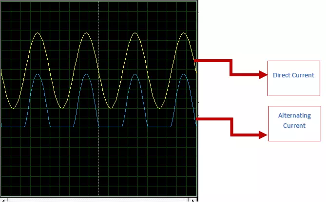
- In Half Wave Rectification, half wave of Alternating(AC) Voltage gets converted into Direct(DC) Voltage, while the other half gets blocked.
- A single diode is used for Half Wave Rectification, as shown in the below figure:
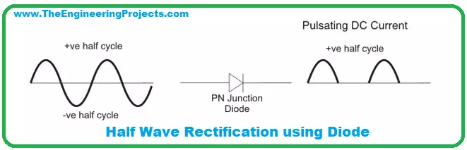
- We can allow either pulse(positive or negative) to pass or block and it depends on the diode's direction.
- In the above figure, we are allowing positive AC pulses to pass, while blocking the negative AC pulses.
- If we reverse the direction of the diode, it will block positive pulses & will allow negative ones.
Full Wave Rectification
- In Full Wave Rectification, a complete alternating(AC) pulse(both positive & negative) gets converted into Direct(DC) voltage.
- As you can see in the above figure, we are now utilizing both cycles of AC current and converting them into DC current.
- Hence, the full wave is more efficient than a half wave, as we have seen half wave simply drops half of the pulse.
Half Wave Rectification in Proteus ISIS
- Proteus is one of the best software for simulating electrical/electronic circuits.
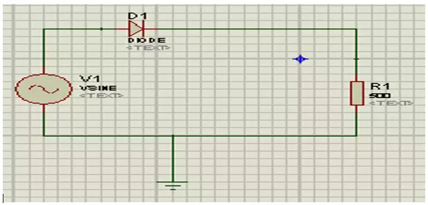
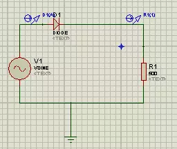
- Basically, we have to design a really simple circuit, as shown in the below figure:
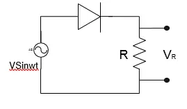
- In order to design this half-wave rectifier, we will need these three components:
- Sine Wave Generator.
- Diode.
- Resistor.
- So, click on the “pick” button and select these components from Proteus Library, as shown in the below figure:
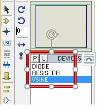
- Now, let's design our circuit, so drag & drop these components one by one in the word space.
- Set the resistor's value to 500 ohms.
- Connect a ground terminal as we are using Vsine i.e. the alternating current source. You will find the GND component in the Terminal area from the left menu.
- Now let's connect the wires, as shown n below figure:
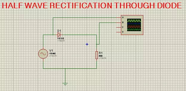
- Once we have completed the basic circuit, we’ll now analyze our output on the Oscilloscope.
- You will find it in the left menu under "Virtual Instruments".
- The Oscilloscope has four terminals named A, B, C, D. We’ll connect Terminal A before Diode and Terminal B after the diode, to analyze both Input and output at the same time.
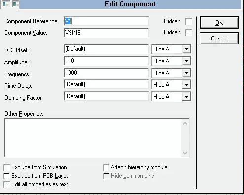
- Double Click on the alternate current source to set the values.
- Here, I am using an amplitude of 110 ms-1 and a frequency of 1000 Hz.
- I have normalized the oscilloscope axes for better examination of the pulses, here are my settings:
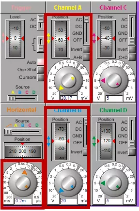
- Now run your Proteus simulation, and if everything goes fine, you will get results, as shown in the below figure:
HWR output through Analog Graph:
In the previous section, we have analyzed the curve with Oscilloscope. Now, we are going to use another awesome feature of Proteus i.e.e Analog Graph. We will plot our input/ output curves of Half wave rectifier on the analog graph in Proteus.
- First of all, remove the oscilloscope from the circuit.
- Select the "Current Source" and place one probe before the diode and one after it, to get both input and output at the same time.
- For the output, take the analog option from the graph terminal. Click on the screen where you want the graph. You can make the size of the graph according to your choice.
- So now you have a blank graph screen. You have to set the parameters, add the trace and then simulate it.
- So, let’s do it. Left-click on the graph screen will show you this dialogue box. Choose add trace.
- This will show you the screen where you can add the traces. Once you have added the traces one by one by clicking the required prob, we can proceed.
- This is the time when you have to edit the graph to show right output. Right click again on the graph screen will let you to see the dialogue box again. This time, you have to choose “Edit Graph”. Choose the value according to need. I am choosing "3m"
- .So, you have set all the required thing. This is the time to stimulate your graph and see the required result.
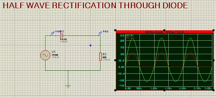
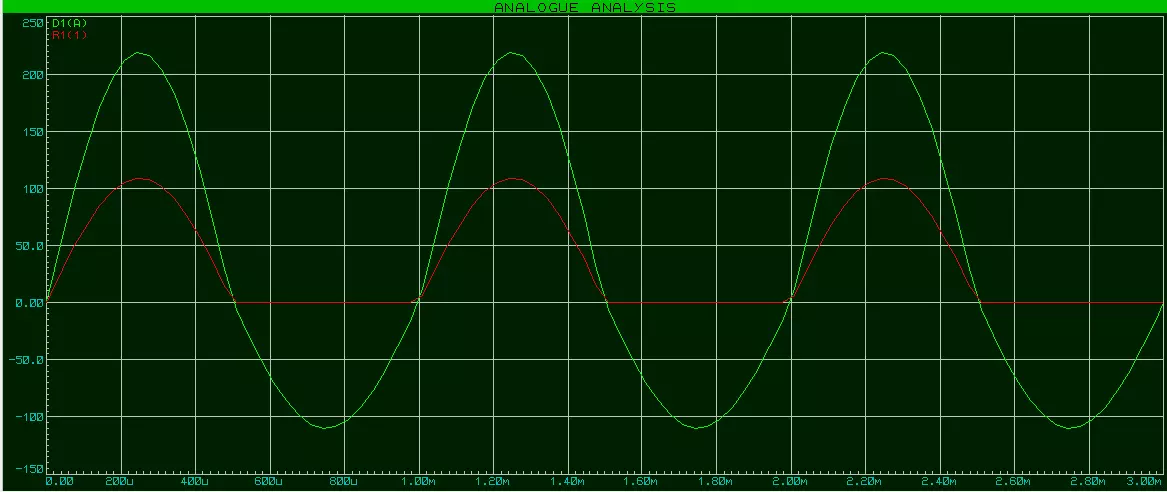
- This is the required result. We give the Input as alternating current, but in the output we got pulsating direct current that flow in one direction.
- We can maximize the result by right click and choosing “Maximize”.
- The green one is the input and the output that is in red is the output i.e. direct current.
So, that was all. This was the tutorial in which we found what is rectification, what is the use of diode in the rectification, how can we use oscilloscope as well as analogue graph to see the result of rectification. For more tutorials and learning stay tuned with us.