JRC4558 Op-Amp Datasheet, Pinout, Features, Alternatives & Applications


Hi Guys! Happy to see you around. I welcome you on board. Thank you for clicking this read. In this post today, I’ll walk you through the Introduction to JRC4558.
The JRC4558 is a single silicon-chip monolithic dual operational amplifier. This amplifier is a high-performance device and is internally compensated. It is widely used in sample and hold amplifiers and pedal circuit designs. The JRC4558 is available with a remarkable input impedance of around 5 MO, a high voltage gain of around 100 dB, and a good slew rate of around 1.7V/µs.
I suggest you buckle up as I will walk you through the complete introduction to JRC4558 covering datasheet, pinout, features, alternatives, and applications. Let’s jump right in.
Introduction to JRC4558
- The JRC4558 is a single silicon-chip monolithic dual operational amplifier that comes with high voltage gain and good input impedance.
- It is applied in portable instrumentation and Intrusion Alarm Systems.
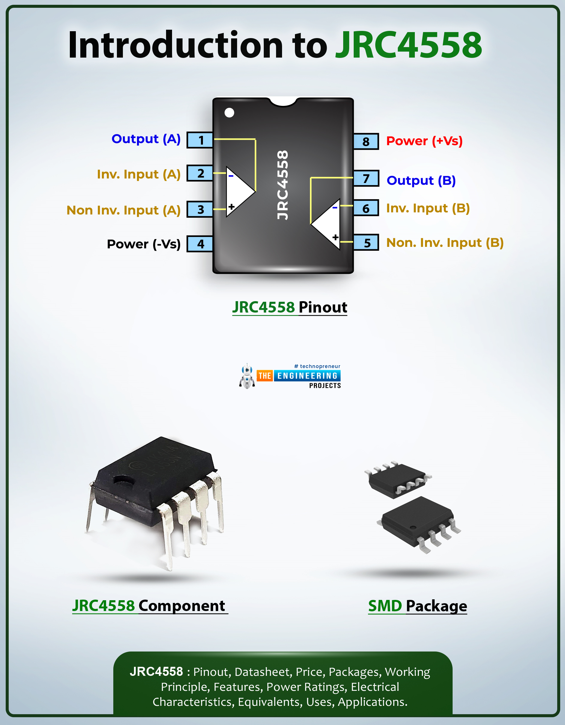
- There are a total of eight pins incorporated on the device, where PIN 8 is the voltage supply pin and pin no 4 is the ground pin. And you’ll get two outputs at the same time.
- There are two inputs i.e. input A and input B and both inputs contain one inverting input (-) with Voltage V- and non-inverting input (+) with voltage V+.
- The ideal op-amps are different from the real op-amps used in this chip. The ideal op-amp comes with infinite gain while the voltage gain of this device is finite and is around 100dB.
- The slew rate of this device is around 1.7V/µs which is achieved when the output voltage of the amplifier reaches its maximum rate of change.

- This chip is incorporated with two independent, good input impedance and internally frequency compensated operational amplifiers that are carefully designed to run over a wide range of voltages from a single power supply.
- The JRC4558 produces an output signal that is much larger than the potential difference at the input.
- It is also applied in general-purpose operational amplifier circuits like differential amplification, comparators, and mathematical operations.
- This device is carefully designed and requires only a 5V standard voltage supply to operate in electronic circuits. You don’t need to include an additional -5V supply to run this device.
- Moreover, it is also employed in single-supply voltage systems, amplification blocks, and transducer amplifiers.
- This device is capable of performing two different operations at the same time as it incorporates two op-amps on board.
- The versatility of this device makes it a good pick for analog circuits.
- It is widely used in scientific devices and industrial and consumer applications.
- This device can be used individually or as a component of most complex integrated circuits.

JRC4558 Datasheet
Before applying this device to your electrical project, it’s wise to go through the datasheet of the component that contains the main characteristics of the component. Click the link below and download the datasheet of JRC4558.
JRC4558 Pinout
The following figure shows the pinout diagram of JRC4558.
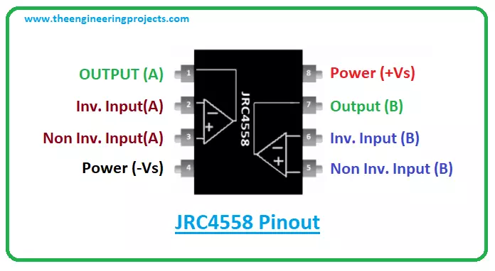
The JRC4558 comes with a total of 8 pins as mentioned below in the table.
| Pin Description of JRC4558 | ||||
|---|---|---|---|---|
| Pin No. | Pin Description | Pin Name | ||
| 1 | The output pin of Op-amp A | OUT (A) | ||
| 2 | The Inverting input pin of the Op-Amp A | Inverting Input (A) | ||
| 3 | The Non-Inverting Input Pin of Op-Amp A | Non- Inverting Input (A) | ||
| 4 | Ground or Negative supply terminal | Power (-Vs) | ||
| 5 | The non-inverting Input Pin of Op-Amp B | Reference | ||
| 6 | The Inverting input pin of the Op-Amp B | Output | ||
| 7 | The output pin of Op-amp B | Power (+Vs) | ||
| 8 | Positive supply terminal | +VS | ||
JRC4558 Features
The following are the main features of the JRC4558.
- No. of Amplifiers = 2
- Voltage Gain = 100 dB
- Device Slew Rate = 1.7V/µs
- Input Impedance = 5 MO
- Available Bandwidth = 3MHz
- Operating Temperature Max = 70°C
- Supply Voltage Range = ± 5V to ± 15V
- of Pins on the component = 8
- Operating Temperature Min = 0°C
- Available Package = 8-Pin DIP and SOP Package
JRC 4558 Alternatives
The following are the alternatives to JRC4558.
- LM158
- LM358
- LM358A
- LM2904Q
- LM158A
- LM2904
- LM747
- LM4558
JRC4558 Applications
The JRC4558 is used in the following applications.
- Applied in Sample and Hold Amplifiers
- Used in Portable Instrumentation
- Employed in Instrumentation Amplifiers
- Used in Long-Duration Timers/Multivibrators
- Incorporated in Intrusion Alarm System
- Employed in Photocurrent Instrumentation
- Used in Comparators and Function Generators
That’s all for today. I hope you’ve enjoyed reading this article. If you are unsure or have any queries, you can pop your question in the section below. I’d love to help you the best way I can. Feel free to share your valuable suggestions and feedback around the content we share, so we keep sharing quality content customized to your exact needs and requirements. Thank you for reading the article.