Hi Guys! I hope you’re doing great. Today, I am going to share Chapter Zero of the ESP32 Programming Course. I have called it Chapter 0 because today, we won't practically work on the ESP32. Instead, I’ll walk you through the detailed theoretical Introduction to the ESP32 Module, where we will discuss the ESP32 Pinout, Datasheet, Specifications, Features, Applications etc. in detail.
ESP32 is an embedded module that supports both WiFi and BT(dual-mode) connectivity and is thus used in Cloud-based IoT projects. ESP32 is the upgraded model of the ESP8266 module and is designed by Espressif Systems in China.
The following tables show the main features and technical specifications of the ESP32 module.
1 core at 240 MHz: 504.85 CoreMark; 2.10 CoreMark/MHz
2 cores at 240 MHz: 994.26 CoreMark; 4.14 CoreMark/MHz
3
Operating Voltage
3.3V
4
DC Current on 3.3V Pin
50 mA
5
DC Current on I/O Pins
40 mA
6
Maximum Operating Frequency
240MHz
7
Frequency Oscillators
8MHz (Internal Oscillator)
Internal RC Oscillatoror
2MHz ~ 60MHz External Crystal Oscillator(40MHz required for WiFi/BT)
32kHz External Crystal Oscillator(For RTC)
8
Timers
2 x 64-bit Timers, 1 RTC Timer,
ESP32 Pinout
1
DAC
2 Channels (8-bit, digital to analog converter)
2
ADC
18 Channels (12-bit, analog to digital converter)
3
Capacitive Touch Sensors
10
4
LED PWM
16 Channels
ESP32 Communication Protocols
1
Wi-Fi
802.11 b/g/n (Speed upto 150Mbps)
2
Bluetooth
Supports Classic Bluetooth v4.2 BR/EDR & Bluetooth Low Energy(BLE)
3
Bluetooth Low Energy
Supports BLE
4
UART Protocol
3 Channels
5
SPI Protocol
4 Channels
6
I2C Protocol
2 Channels
7
I2S Protocol
2 Channels (for digital audio)
8
CAN Protocol
1 Channels
ESP32 Builtin Memory
No.
Parameter Name
Parameter Value
1
SRAM
520kb
2
ROM(Flash Memory)
448kb
3
RTC SRAM
16kb
So, let's get started with the Introduction to ESP32:
Introduction to ESP32 Module
ESP32
(designed by Espressif Systems, a Shanghai-based Chinese Company) is a 48 Pinmicroprocessor-based
embedded IC(available in QFN package), that supports both WiFi & BT(dual-mode) connectivity
and is used majorly in wearable devices, mobile & cloud-based IoT applications.
The microprocessor used in the ESP32 chip is the Tensilica Xtensa LX6 microprocessor
(single-core and dual-core).
A few LX6 based ESP32 ICs are:
ESP32-D0WDQ6 (and ESP32-D0WD)
ESP32-D2WD
ESP32-S0WD
ESP32-PICO-D4
ESP32 vs ESP8266
Both the ESP32 and ESP8266 are inexpensive WiFi modules with low power consumption.
Both modules are desirable for DIY projects in the areas of IoT (Internet of Things) and automation.
The ESP32 is a dual-core 160Mhz 240Mhz CPU, while the ESP8266 has an 80Mhz single-core processor. Therefore, if your primary concern is processor speed, you should prioritize the ESP32 over the ESP8266.
The ESP32 offers more GPIO than the ESP8266.
ESP32 supports Bluetooth 4.2 and BLE(Bluetooth Low Energy).
The ESP32 offers a 12-bit ADC, while the ESP8266 offers only a 10-bit ADC.
ESP32-WROOM-32
ESP32-WROOM-32
is a 38-pin
breakout board of ESP32, which is most commonly used in third-party ESP32 modules.
As ESP32 IC is available in the QFN(Quad Flat No Leads) package, so it's quite difficult to solder the IC in embedded projects.
So, to ease the process of using ESP32 IC, Espressif Systems
designed numerous small modules(using ESP32 chip) that have a built-in
antenna and easily usable pinout.
Other ESP32 modules are ESP32-SOLO and ESP32-WROVER.
One of the most commonly used breakout boards of ESP32 is ESP32-WROOM-32, shown in the below figure:
Third-Party ESP32 Development Modules
Many embedded companies have used ESP32-WROOM-32 and
designed different ESP32 development boards, which are plug-and-play
modules and are thus normally used for learning and prototyping
purposes.
One of the most commonly used ESP32 development boards is called ESP32-DevkitC.
ESP32-DevKitC
is a 30-pin ESP32-based development board, designed by Espressif Systems and is used in embedded and IoT projects.
All you need to do is plug this device using a USB cable and play with it on the fly.
Boot mode and Reset
buttons are incorporated on the board.
USB micro connector and USB-UART Bridge, and LDO regulator are also included in the device.
Types of ESP32 Development Boards
The following are the five different versions of ESP32-DevKitC.
ESP32-DevKitC-32E
ESP32-DevKitC-32UE
ESP32-DevKitCVE
ESP32-DevKitCVIE
ESP32-DevKitCS1
So, that was the evolution of ESP32 from a simple IC to plug & play board. Now let's have a look at the Pinout of the ESP32 microcontroller and modules:
ESP32 Pinout
We have seen above that ESP32 has evolved first into ESP32-WROOM-32 and is further upgraded into ESP32-DevKitC. So, let's have a look at the pinout of all these boards, one by one:
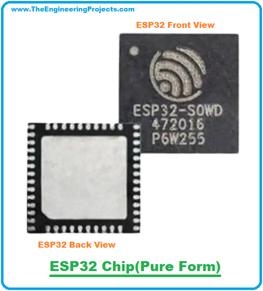
Pinout of ESP32 IC
ESP32 IC in its pure form consists of 48 pins
in total.
The following figure shows the labeled ESP32 Pinout
diagram:
Pinout of ESP32-WROOM-32
ESP32-WROOM-32 is a breakout board of ESP32 and consists of 38 pins in total.
Here's the pinout of the ESP-WROOM-32 board:
Pinout of ESP32-DevkitC
ESP32-DevKitC is a development board based on the ESP32 microcontroller and it has 36 pins in total.
Here's the pinout diagram of ESP32 DevKitC:
ESP32 Pin Description
Now, let's have a look at the functions of ESP32 Pinout:
Power Pins in ESP32
Power:
Power is applied through Micro-USB, 3.3V pin, 5V pin, and GND. Regulated 5V is supplied to this pin which is further regulated to 3.3V to power up the board. And 3.3V pin directly supplies the 3.3V regulated to the board. And the ground is connected to GND.
Enable: The enable pin is represented by ‘En’ on the board and is used to reset the microcontroller.
AREF: It is marked as AREF which is used to provide a reference voltage for input voltage.
GPIO Pins in ESP32
ESP32 has 36 GPIO(general purpose input/output) pins to perform numerous operations(normally one at a time). Third-party ESP32 modules have different numbers of GPIO pins i.e. ESP32 Dev Kit V1 includes 30 GPIO pins. Let's have a look at the functionality of ESP32 GPIO Pins:
ADC Pins in ESP32
ADC Pins: ESP32 has a total of 18 ADC channels(12-bit each) used to measure the analog voltage within the range of 0-3.3V.
ESP32 is equipped with two SAR analog-to-digital converter modules named ADC1 and ADC2. ADC1 has 10 Channels labeled from ADC2_1 to ADC2_7, while ADC2 has 10 Channels labeled from ADC2_0 to ADC2_9. The ADC output value ranges from 0 to 4093 at 12-bit resolution.
DAC Pins in ESP32
DAC Pins: ESP32 features 2 distinct 8-bit
digital-to-analog converters(DAC1 and DAC2) for translating digital values to analog signals. The DAC function is attached to below two GPIO pins:
DAC1-GPIO25
DAC2-GPIO26
The DAC employs a power supply as an input reference voltage and features an internal resistance network.
PWM Pins in ESP32
PWM Pins: ESP32's PWM controller has 16 independent PWM channels with configurable frequency and duty cycles. Any GPIO pin can be used as a PWM pin.
PWM pulses are used to control the speed of motors or the brightness of LEDs. You can configure the frequency, channel, GPIO pin, and duty cycle of the PWM signal.
SPI Pins in ESP32
SPI Pins: ESP32 has three SPI blocks that operate in both master and slave modes, named SPI, HSPI, and VSPI.
Among these 3 blocks, SPI is used as an interface to flash
memory. So, we are left with HSPI and VSPI for normal use:
VSPI: ESP32 VSPI Pins are GPIO23 (MOSI), GPIO19 (MISO), GPIO18 (CLK) and GPIO5 (CS) used for SPI-1 communication.
HSPI: ESP32 HSPI Pins are GPIO13 (MOSI), GPIO12 (MISO), GPIO14 (CLK) and GPIO15 (CS) used for SPI-2 communication.
I2C Pins in ESP32
The ESP32 has two I2C interfaces. The SCL and SDA pins of both I2C interfaces can be assigned by a user in the program. The default I2C pins are:
SDA-GPIO21
SCL-GPIO22
ESP32 Capacitive Touch Sensors
ESP32 has 10 capacitive touch-sensing GPIO Pins(T0 to T9), which get electrostatically charged when a finger touches the respective GPIO pin.
Without any additional hardware, these touch GPIOs can be utilized to make capacitive touchpads. Variations in capacitance are evident.
RTC GPIO
ESP32 has 18 Low-Power RTC GPIO Pins(RTCIO0 to RTCIO17) used to wake up the ESP32 board from deep sleep mode.
Serial: Two serial pins are represented on boards as Tx and Rx. The Tx is used to transmit serial data while Rx is used to receive serial data.
External Interrupts: All GPIO pins can be used as external interrupts.
ESP32 Datasheet
Before you incorporate this device into your electrical project, it’s wise to go through the datasheet of the component that features the main characteristics of the device. You can click the link given below to download the ESP32 datasheet.
Now, let's have a look at the features of ESP32:
ESP32 Features
Here are the main features of ESP32 IC:
ESP32 has built-in integration of both WiFi and Bluetooth dual-mode.
ESP32 has 34 programmable GPIOs
present on the chip.
ADC is of 12-bit
SAR and can support up to 18 channels.
DAC is 8-bit
and it has 2 DAC channels.
ESP32 also has 10 touch sensors
embedded in it.
ESP32 also has a Hall sensor
in it.
It supports 4 SPI channels.
It also has 2 I²S channels.
ESP32 has 2 I²C ports
in it.
It supports 3 UART channels.
It also has 1 host(SD/MMC/SDIO)
and 1 slave(SDIO/SPI).
ESP32 also supports the Ethernet MAC interface
with dedicated DMA and IEEE 1588
support.
It supports Two-Wire
Automotive Interface (TWAI®, compatible with ISO11898-1)
LED PWM up to 16 channels
A few of ESP32's key features are discussed below in detail:
ESP32 WiFi Key Features
Wireless Networking Standard: 802.11 b/g/n
Wireless Standard: 802.11 n (2.4 GHz), up to 150 Mbps
WiFi Multimedia(WMM)
WiFi Aggregation: TX/RX A-MPDU, RX A-MSDU
Immediate Block ACK:
suitable for high bandwidth & low latency traffic.
Automatic Beacon monitoring
(hardware TSF)
Simultaneous support for SoftAP, Infrastructure Station and Promiscuous modes.
Diverse Antenna
Defragmentation
to smoothen the data.
Supports 4 virtual WiFi Interfaces.
ESP32 Bluetooth Key Features
Compliant with Bluetooth v4.2 BR/EDR
Class-1, Class-2 and Class-3
transmitters without external power amplifier
Increased Power Control
Transmission Power: +12 dBm
BLE sensitivity: –94 dBm (NZIF receiver)
Adaptive Frequency Hopping (AFH)
Standard HCI supports SDIO/SPI/UART
High-speed UART HCI, up to 4 Mbps
Bluetooth 4.2 BR/EDR BLE dual-mode controller
CVSD and SBC
for audio codec
Classic BT and BLE
support Multiple connections.
It can advertise and scan simultaneously.
Bluetooth Piconet and Scatternet
ESP32 Microcontroller Key Features
ESP32 uses an Xtensa® single-/dual-core 32-bit LX6 microprocessor(s)
.
It supports data rates up to 600 MIPS
(200 MIPS for ESP32-S0WD/ESP32-U4WDH)
It has a Flash Memory of 448 KB.
It has an SRAM memory of 520 KB.
16 KB SRAM in RTC
QSPI
supports multiple flash/SRAM chips.
ESP32 Clocks & Timers Key Features
ESP32 has a calibrated 8MHz crystal oscillator
(internal)
Calibrated RC oscillator
(internal)
External 2 MHz ~ 60 MHz
crystal oscillator (40 MHz only for Wi-Fi/BT functionality)
External 32 kHz
crystal oscillator for RTC with calibration
Two timer groups, including 2 × 64-bit timers
and 1 × main watchdog in each group
ESP32 also has one RTC timer.
RTC watchdog
is also present in ESP32.
ESP32 Projects & Applications
ESP32 modules have brought a revolution in embedded and especially
IoT projects. As these boards are small-sized, low-powered and support
both WiFi & BT, thus are gaining popularity in IoT-based handheld
devices. A few applications of the ESP32 module are as follows:
Used in Network projects.
Employed for beginner-level DIY projects.
Employed in the prototyping of IoT devices.
Used in cloud-based smart security projects.
Used in low-power battery-operated applications.
That was all about the Introduction to ESP32 module. If you have any questions, you can approach me in the comment section below. I’ll help you according to the best of my expertise. You’re most welcome to share your valuable feedback and suggestions around the content we share so we keep coming up with quality content customized to your exact needs and requirements. Thank you for reading the article.
hello james
Thank you so much for this breakdown :) its saved my butt a few times - and i have your diagram printed and my bread board glued to it :P
there's some labeling on it that i don't understand yet though, perhaps you can help me?
CHIP PU, SENS VP, SENS VN, VDET1, VDET2 for instance.
and there's the pins labeled 39 and 42 - i am currently using those for my OLED display actually - in purple they're GPIO22 and 21 respectively, but in gold they're 23 and VSPI HD. Could you help clear that up for me?