ESP32 PWM(Pulse Width Modulation) in Arduino IDE


Hello readers, I hope you all are doing great. Welcome to the 3rd Lecture of Section 2 in the ESP32 Programming Series. In this tutorial, we are going to discuss another important feature of ESP32 i.e. PWM(Pulse Width Modulation).
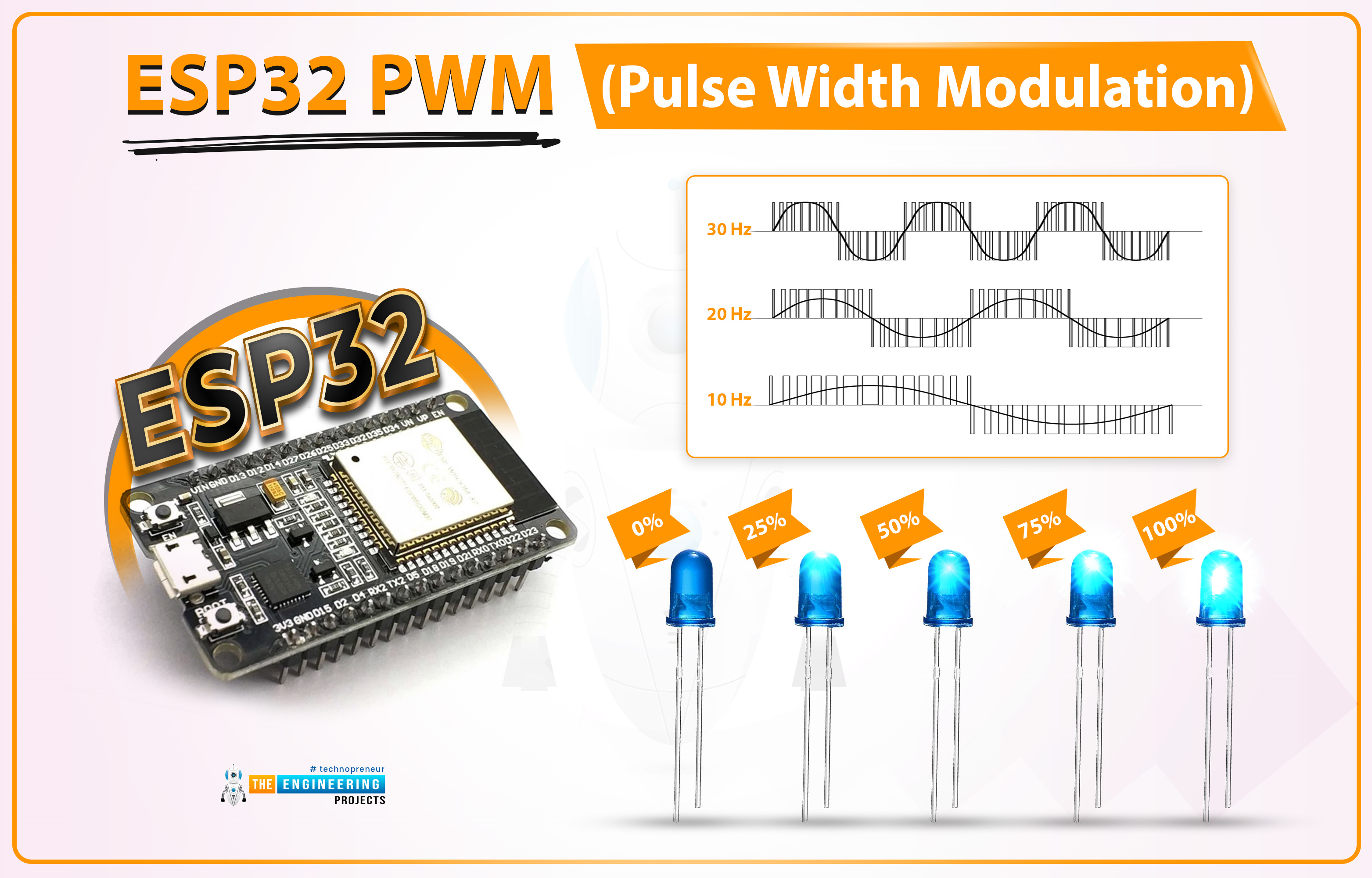
Pulse Width Modulation is a technique to reduce the voltage by pulsating it. In today's lecture, we will first understand the basic concept of PWM, and after that will design two projects to fully grasp it. In the first project, we will control the brightness of an LED, while in the second one, we will control the speed of a DC Motor.
- Here's the video demonstration of PWM Control in ESP32:
Before going forward, let's first have a look at the PWM working:
What is Pulse Width Modulation?
PWM is used to control the power delivered to the load by pulsating the ON-Time of the voltage pulse, without causing any power loss. Let's understand the PWM concept with the help of below image:
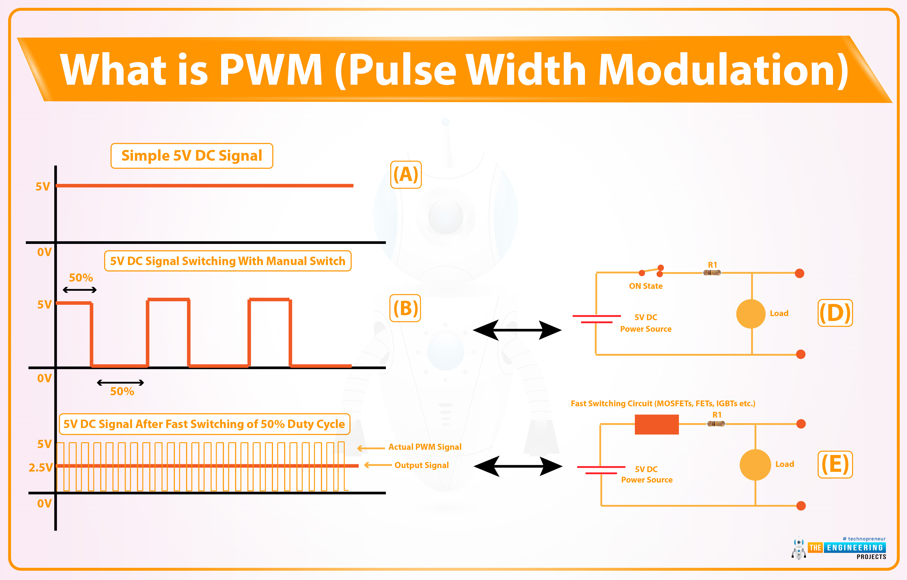
- As you can see in the above image, Figure A shows a simple 5V DC signal.
- Figure D shows a simple circuit with a manual switch, now if we turn the switch ON & OFF manually, the Load will also behave in the same way. Its waveform is shown in Figure B, when the switch is ON, we are getting +5V and when it's OFF, output is 0V.
- Instead of manual switching, if we place a fast automatic switching circuit (FETs, MOSFETs etc.), the output pulse won't show fluctuations, instead, it will get steady but its overall power will be reduced.
- Let's understand the working of PWM with an example:
Suppose a DC Motor runs at 200RPM over 5V. Now, if we want to reduce its speed to 100 RPM, we need to reduce its input voltage to 2.5V(approx). So, either we can replace the 5V battery with a 2.5V Battery or use a PWM circuit to reduce the voltage level from 5V to 2.5V. In this specific case, the PWM pulse will be ON for 50% of the time and get OFF for the remaining 50% of the time.
The behavior of the PWM signal is determined by the following factors:
- Frequency
- Duty Cycle
- Resolution
PWM Frequency:
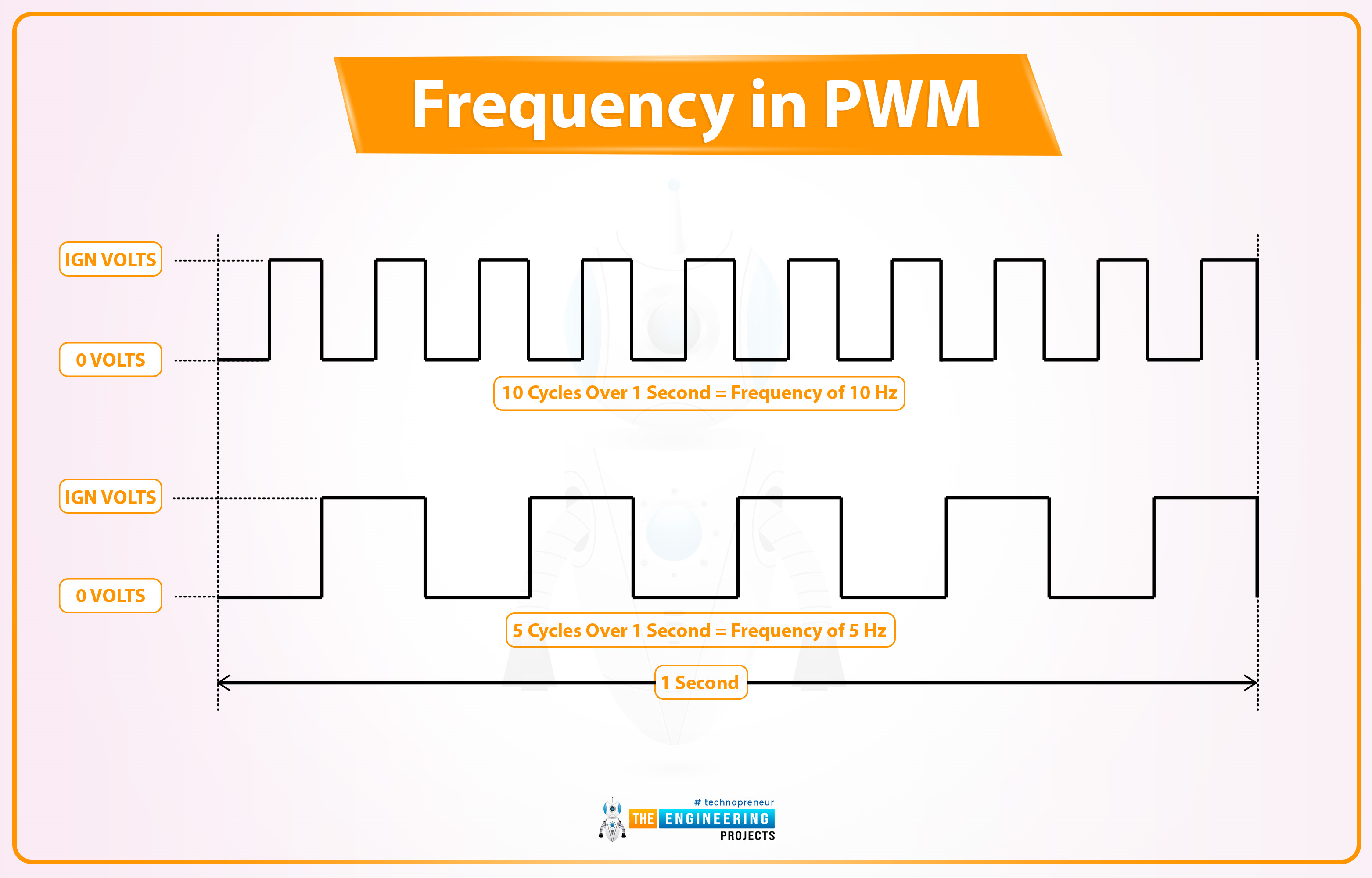
- The Frequency of a signal is defined as the number of cycles per second, denoted by "f" and the measuring unit is hertz(Hz).
- The Frequency (f) of a signal is inversely proportional to its time period(t).
- Let's understand the signal Frequency with the help of below image:
As you can see in the below figure, we have taken two signals for a duration of 1 second. The first signal completes 10 Cycles in 1 second, so we can say it has a frequency of 10Hz, while the second one has a frequency of 5Hz as it completes 5 cycles in 1 second. So, I hope now it's clear that the number of cycles per second is the frequency of a signal.
- The frequency of a PWM signal depends on the provided clock source.
- In the case of microcontrollers, the clock source is provided by the crystal oscillator. So, a 40MHz Crystal Oscillator can produce high-frequency PWM signals as compared to a 20MHz oscillator.
PWM Duty Cycle:
Duty Cycle is the ratio of ON time(when the signal is high) to the total time taken to complete the cycle. The duty cycle is represented in the form of a percentage (%) or ratio. Let's understand the PWM Duty Cycle with the help of below image:
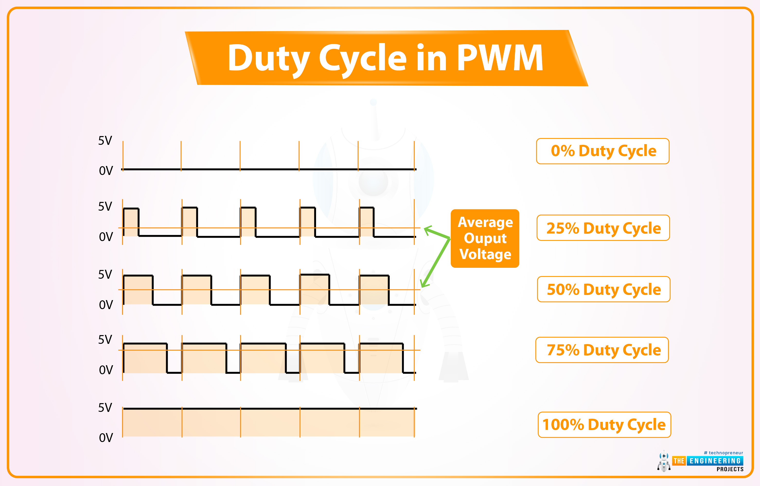
- The 1st graph shows no signal, so we can say it has a 0% Duty Cycle because there's no ON-Time.
- The 2nd graph shows 5 cycles of a signal and in each cycle, the signal is ON only for 25% of the total time. So, its Duty Cycle is 25%.
- In the 3rd graph, the signal has a duty cycle of 50% because it's HIGH for 50% of the cycle.
- You can calculate the 4th graph, its duty cycle is 75% as it is HIGH for 75% of the total duration.
- The last graph shows a pure DC Signal of 5V, and as it is HIGH for the whole cycle, its duty cycle will be 100%.
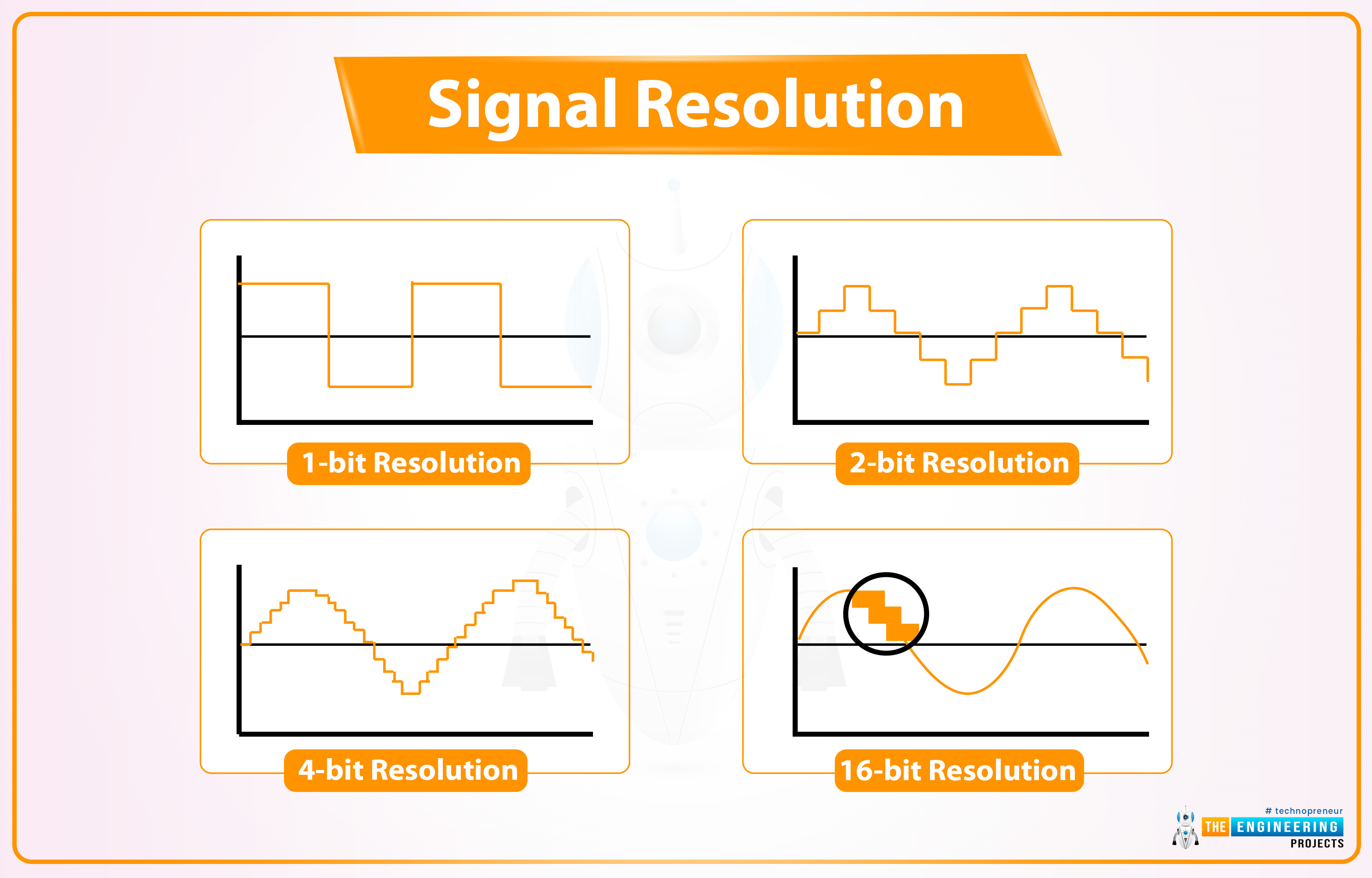
Resolution:
The resolution of a PWM signal defines the number of steps it can have from zero power to full power. The resolution of the PWM signal is configurable for example, the ESP32 module has a 1-16 bit resolution, which means we can configure maximum a of 65536 (2^16) steps from zero to full power.
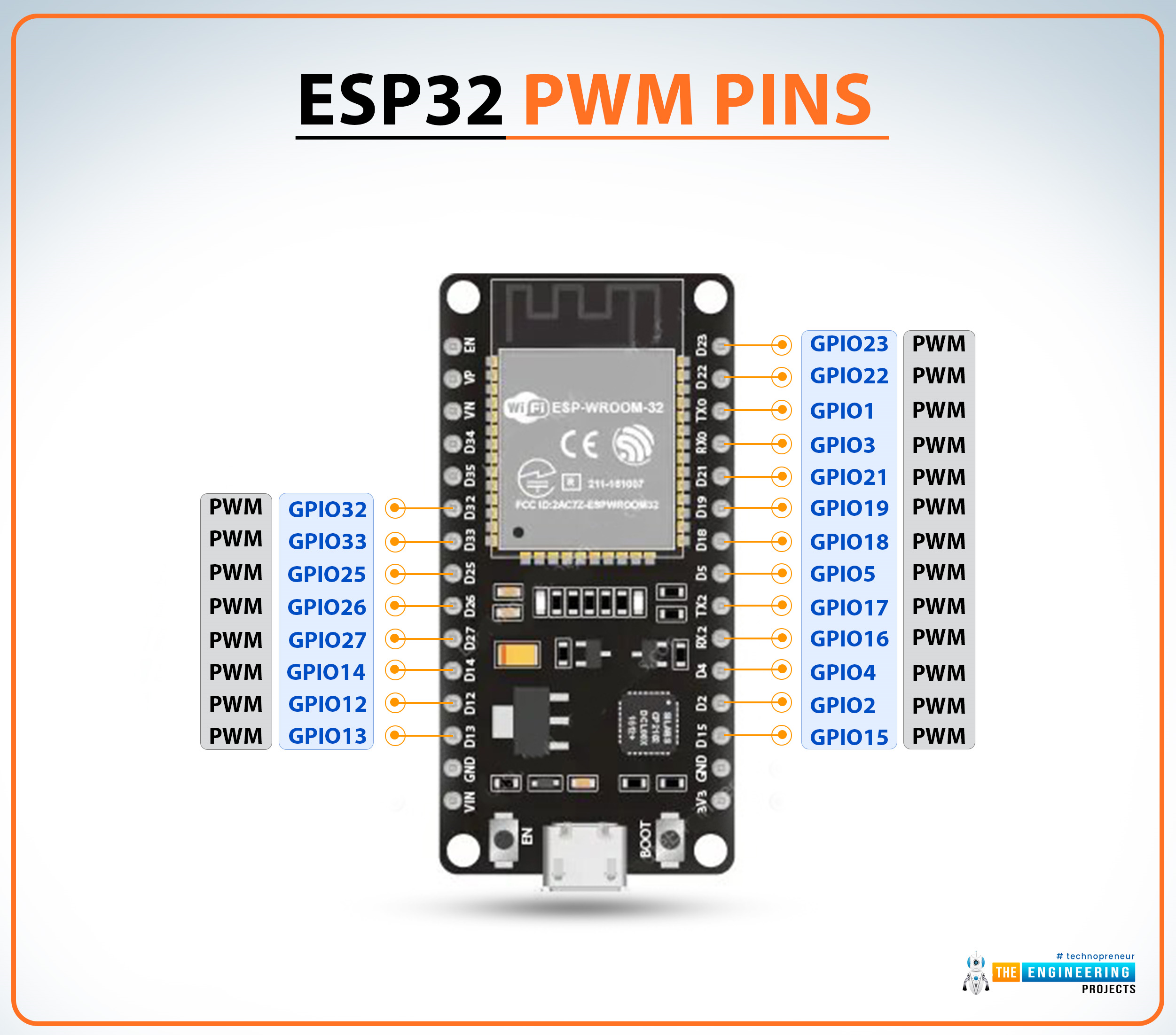
Implementing PWM using ESP32
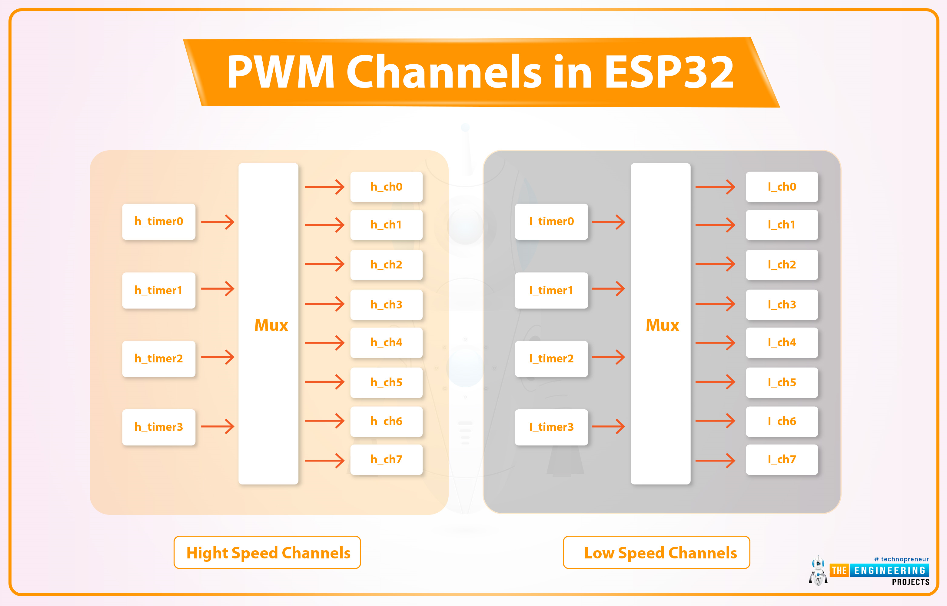
In the ESP WROOM-32 module, there are 16 PWM channels. All the channels are divided into two groups containing 8 channels in each group. The resolution can be programmed between 1 to 16 bits and frequency also depends upon the programmed resolution of the PWM signal.
Now
For the demonstration of PWM in ESP32 we are going to explain two examples:
- Controlling LED brightness using PWM
- Controlling DC motor speed using PWM
ESP32 Code for Controlling LED brightness using PWM
We are using Arduino IDE to compile and upload the code into the ESP WROOM-32 board.
- If you are new to Arduino IDE and ESP32 then follow our previous tutorial, Introduction to ESP32 programming series for detailed information.
- ESP32’s inbuilt LED is used in this code. You can also connect an external LED as per your requirements.
Arduino IDE Code:
// Global variable declaration to set PWM properties
const int ledChannel = 0; // select channel 0
const int resolution = 8; //8-bit resolutin i.e., 0-255
const int frequency = 5000; // set frequency in Hz
int dutyCycle = 0;

void setup()
{
    Serial.begin(115200);
    ledcSetup(ledChannel, frequency, resolution); // configure LED PWM functionalities
    ledcAttachPin(LED_BUILTIN, ledChannel); // attach the channel to the GPIO to be controlled
}

void loop()
{
    while(dutyCycle <200)
    {
        ledcWrite(ledChannel, dutyCycle++); // changing the LED brightness with PWM
        Serial.print(" duty Cycle ++ :");
        Serial.println(dutyCycle); // display the duty cycle on serial monitor
        delay(5);
    }
    while(dutyCycle>0)
    {
        ledcWrite(ledChannel, dutyCycle--); // changing the LED brightness with PWM
        Serial.print(" duty Cycle -- :");
        Serial.println(dutyCycle); // display the duty cycle on serial monitor
        delay(5);
    }
}
Code Description
Global Variable declaration:
- The first step is to declare variables for setting PWM properties.
- As we have already mentioned that ESP WROOM-32 has 16 PWM channels (0 to 15). So, the first step will be to select a PWM channel between 0-15. In the Arduino IDE code, we are using PWM channel_0 to generate a PWM signal.
- The next step will be to choose the resolution. The maximum resolution for ESP32 is 16-bit. You can choose any value between 1-16. PWM resolution is the factor that decides the maximum duty cycle.
- For example, if we choose 10-bit resolution then the maximum duty cycle of the output signal will be 2^10 that is 1024 (0-1023) and similarly, for 8-bit resolution the duty cycle will be 2^8=256 (0- 255).
- 5KHz or 5000Hz is the PWM signal frequency.
- We also need to initialize a variable to store the duty cycle value.
// Global variable declaration to set PWM properties
const int ledChannel = 0; // select channel 0
const int resolution = 8; //8-bit resolutin i.e., 0-255
const int frequency = 5000; // set frequency in Hz
int dutyCycle = 0;
Arduino Setup() Function
- Inside setup() function we are going to start serial monitor at 115200 baud rate.
Serial.begin(115200);
- To configure PWM properties we are calling the ledcSetup() function which uses PWM properties (like PWM channel, frequency and PWM resolution) as arguments.
ledcSetup(ledChannel, frequency, resolution); // configure LED PWM functionalities
- ledcAttachPin() function is used to assign the LED_BUILTIN pin to the PWM channel.
ledcAttachPin(LED_BUILTIN, ledChannel); // attach the channel to the GPIO to be controlled
Arduino Loop() Function
- Inside the loop function, we going to run a conditional control loop (while loop) to change the LED brightness along with the change in duty cycle.
- At first, the value of the duty cycle is going to increase continuously until it reaches max 8-bit resolution ( that is 255).
- The serial monitor will print the duty cycle value with some delay.
while(dutyCycle <200)
    {
        ledcWrite(ledChannel, dutyCycle++); // changing the LED brightness with PWM
        Serial.print(" duty Cycle ++ :");
        Serial.println(dutyCycle); // display the duty cycle on serial monitor
        delay(5);
    }
- After increasing the duty cycle to maximum resolution another while loop is used to decrease the duty cycle to value 0 from 255 and proportionally the LED brightness and the PWM output will be printed on the serial monitor.
while(dutyCycle>0)
{
    ledcWrite(ledChannel, dutyCycle--); // changing the LED brightness with PWM
    Serial.print(" duty Cycle -- :");
    Serial.println(dutyCycle); // display the duty cycle on serial monitor
    delay(5);
}
Code Testing
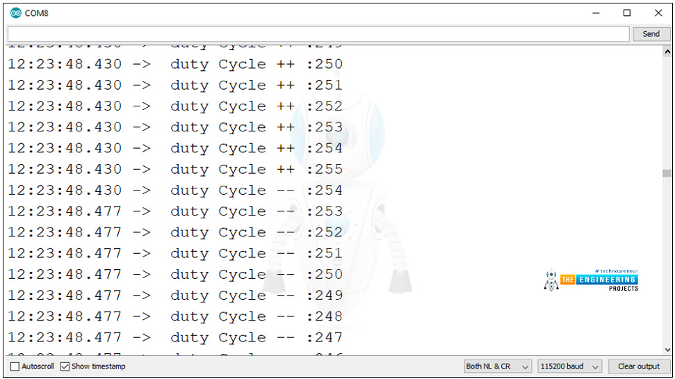
- You can see the change in the value of the duty cycle on the serial monitor. We have attached a screenshot below from the Arduino IDE serial monitor for reference.
- For a better understanding of PWM output you can use an oscilloscope (either CRO or DSO) by connecting the PWM output pint and GND pint to the oscilloscope probe, if available.
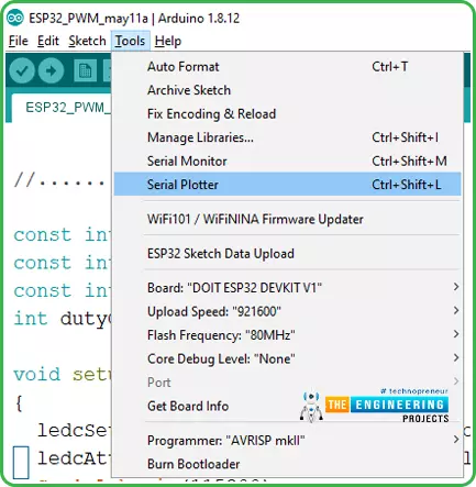
- You can also use a serial plotter to see the PWM output if you do not have an oscilloscope.
- To access the serial plotter, use sort-cut key shift+ctrl+L or follow the image attached below:
- We have attached a screenshot of the PWM output waveform from the serial plotter for better understanding.
- You can vary the value of duty cycle anywhere between 0-8 bit resolution.
- For example in the image attached below the duty cycle is 200.
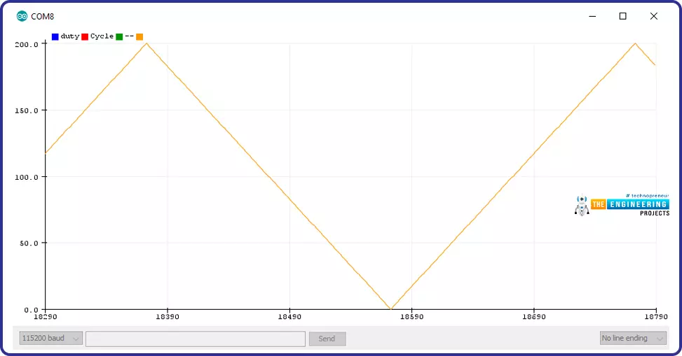
Fig. 9 Serial plotter PWM output
ESP32 Code for Controlling DC motor speed using PWM
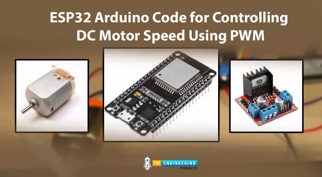
Fig. 10
In this example, we are going to implement PWM using ESP WROOM-32 to control the speed of a DC motor.
The speed of the DC motor depends upon the input power supply. So, by varying the power input we can also vary (increase or decrease) the speed of DC motor.
Hardware components required:
- ESP WROOM-32 board
- DC motor
- L298N motor driver
- Connecting wires
- Data cable
L298N motor driver: A motor driver is used between the ESP32 board and DC motor to resolve the power compatibility issues.
Both the ESP32 board and DC motor operate at different power ratings due to which you can not connect the two devices directly. So a motor driver is used to receive a low power input from the ESP32 board and drive/run DC motor at slightly high power.
L298N can drive a DC motor that operated between 5 to 35 voltage range and maximum current of 2A.
There are various DC motor drivers available in the market for example L293D, DRV8833, MAX14870 single brushed motor driver etc. You can choose the driver of your choice depending upon the application and power ratings.
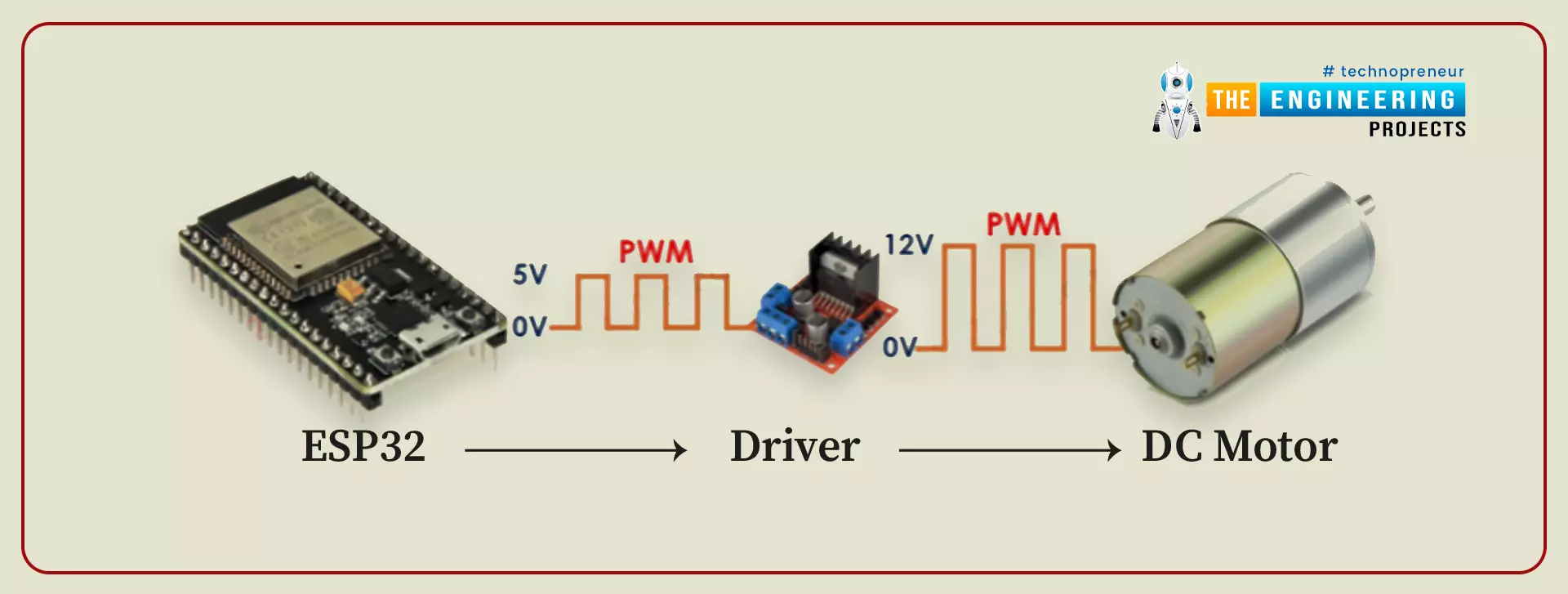
Fig. 11
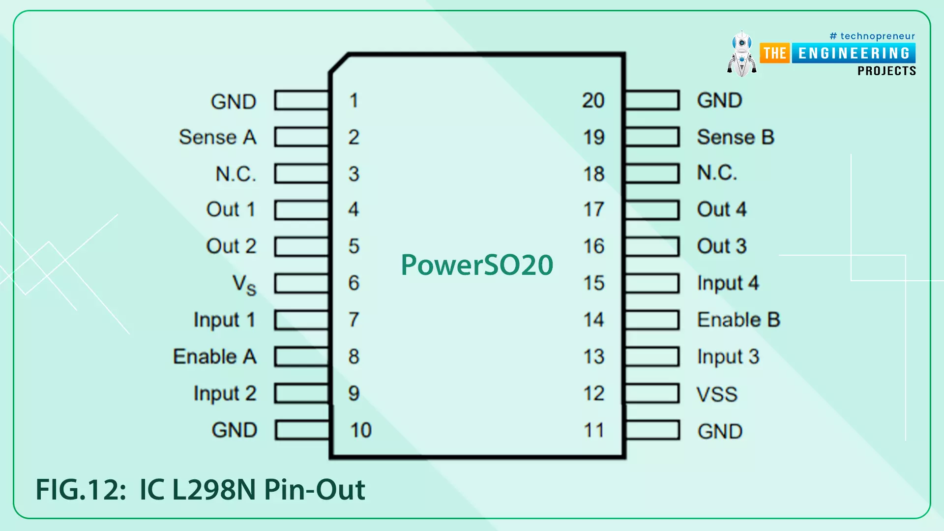
FIG. 12 IC L298N pin-out
- You can also change the direction of rotation by connecting the input as per the table drawn below:
| IN_1 | IN_2 | Rotation |
| HIGH | LOW | DC motor rotates in a clockwise direction |
| LOW | HIGH | The motor rotates in an anti-clockwise direction |
| LOW | LOW | Motor STOP |
| HIGH | HIGH | Motor STOP |
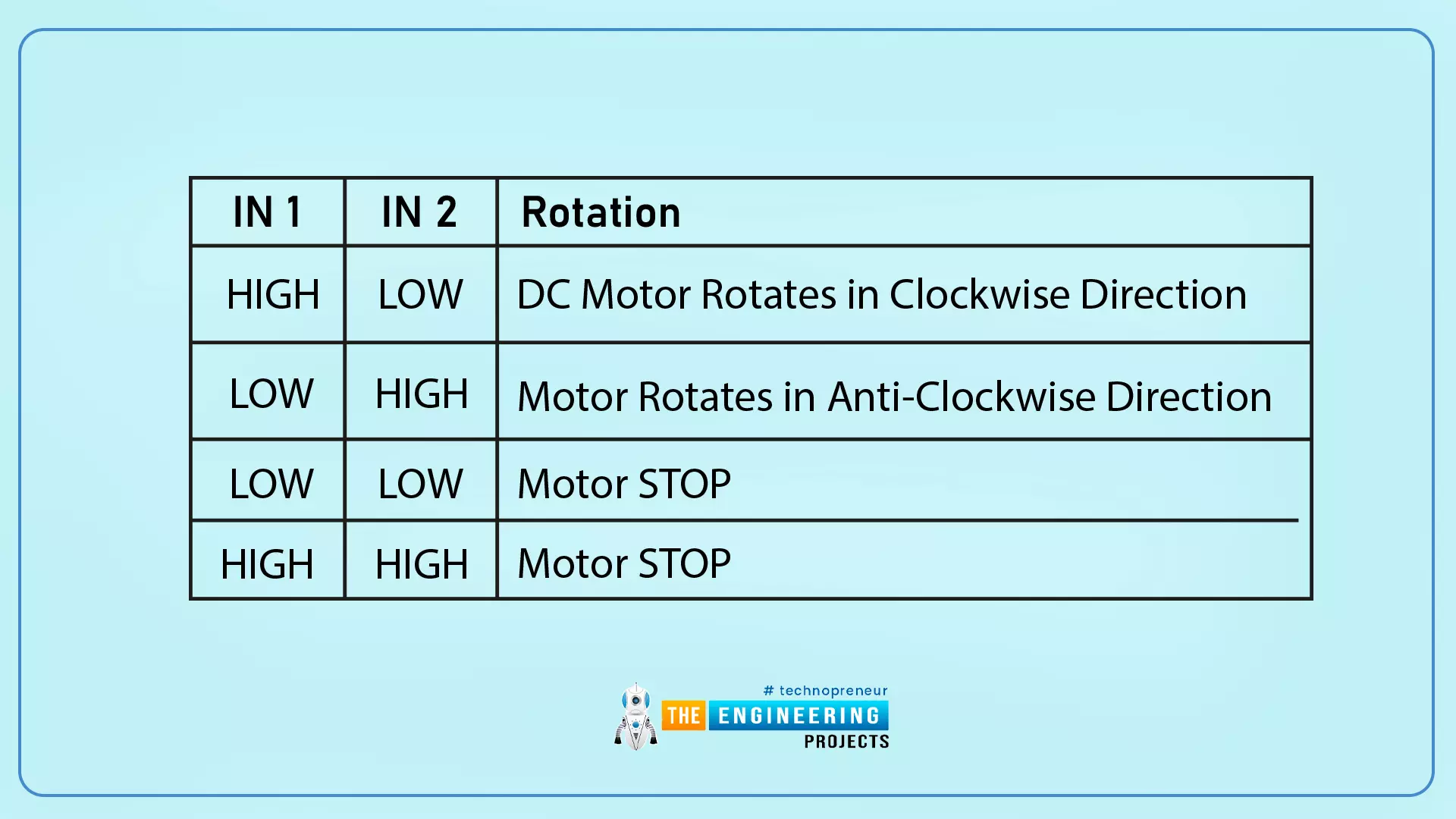
Table 1
Arduino Code
//configure GPIO pins to connect motor driver
int enable1Pin = 14;
int M_Pin1 = 26;
int M_Pin2 = 27;

// Setting PWM properties
const int freq = 10000;
const int pwmChannel = 0;
const int resolution = 8;
int dutyCycle = 150;

void setup()
{
    Serial.begin(115200);

    // sets the pins as outputs:
    pinMode(M_Pin1, OUTPUT);
    pinMode(M_Pin2, OUTPUT);
    pinMode(enable1Pin, OUTPUT);

    //Configure LED PWM functionalities
    ledcSetup(pwmChannel, freq, resolution);

    // attach the channel to the GPIO to be controlled
    ledcAttachPin(enable1Pin, pwmChannel);

    Serial.print("Testing DC Motor...");
}

void loop()
{
    // Move the DC motor in anti-clockwise direction at maximum speed
    Serial.println("Moving reverse");
    digitalWrite(M_Pin1, LOW);
    digitalWrite(M_Pin2, HIGH);
    delay(500);

    // Move DC motor forward with increasing speed
    Serial.println("Moving Forward");
    digitalWrite(M_Pin1, HIGH);
    digitalWrite(M_Pin2, LOW);

    //----while loop----
    while (dutyCycle <= 255)
    {
        ledcWrite(pwmChannel, dutyCycle);
        Serial.print("Speed increasing with duty cycle: ");
        Serial.println(dutyCycle);
        dutyCycle = dutyCycle +5;
        delay(100);
    }

    while (dutyCycle >150)
    {
        ledcWrite(pwmChannel, dutyCycle);
        Serial.print("Speed decreasing with duty cycle: ");
        Serial.println(dutyCycle);
        dutyCycle = dutyCycle -5;
        delay(100);
    }

    // _____Stop the DC motor
    Serial.println("STOP DC motor");
    digitalWrite(M_Pin1, LOW);
    digitalWrite(M_Pin2, LOW);
    delay(500);
}
Code Description
- The first step is to configure GPIOs which are to be connected with the DC motor driver (L298N).
- Here we are using three GPIOs, the first one is connected with the Enable_A pin and the rest of the two are connected with motor inputs.
- You can also control 2 motors with the same driver using Enable_2 and its respective input pins.
//configure GPIO pins to connect motor driver
int enable1Pin = 14;
int M_Pin1 = 26;
int M_Pin2 = 27;
- The next step is to define variables to store PWM properties as discussed in the previous example.
- You can vary the frequency and duty cycle of the PWM signal as per your requirements but, within the desired range.
- Here we are assigning 10000Hz or 10KHz frequency with 8-bit resolution (0-255 duty cycle) and the initial duty cycle value is 150 for PWM channel 0.
// Setting PWM properties
const int freq = 10000;
const int pwmChannel = 0;
const int resolution = 8;
int dutyCycle = 150;
Arduino Setup() Function
- Inside the setup function, the first task is to initialize the serial monitor with a 115200 baud rate.
Serial.begin(115200);
- Set the operating mode of three GPIO pins (which are to be connected with motor driver board) as output.
// sets the pins as outputs:
pinMode(M_Pin1, OUTPUT);
pinMode(M_Pin2, OUTPUT);
pinMode(enable1Pin, OUTPUT);
- Call the function ledcSetup() to configure PWM properties by passing PWM properties as arguments.
//Configure LED PWM functionalities
ledcSetup(pwmChannel, freq, resolution);
- Next, you need to select the GPIO pin which will provide the PWM output from ESP32 to the motor driver using ledcAttachPin() function which uses the PWM output pin and PWM channel as two arguments.
// attach the channel to the GPIO to be controlled
ledcAttachPin(enable1Pin, pwmChannel);
Arduino Loop() Function
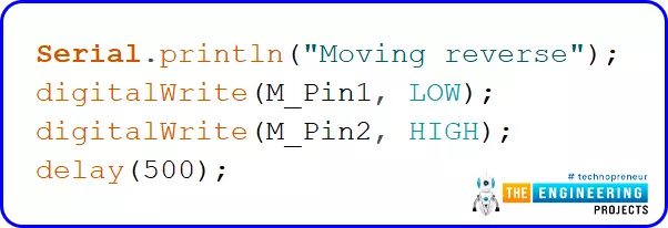
- Start rotating the motor in the anti-clockwise direction. Follow Table 1 for more details regarding the direction of rotation.
- Add the delay of 0.5 sec or as per your requirements.
- Rotate the DC motor in a clockwise direction by setting M_PIN1 as high ND m_Pin2 as low.
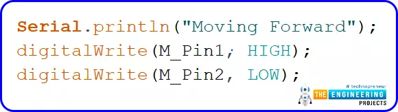
Fig. 20
- As we have initialized the duty cycle variable with a value of 150. Now, increase the motor speed by increasing the value of the Duty cycle from 150 by increasing 5 steps continuously until it reaches the maximum value that is 255.
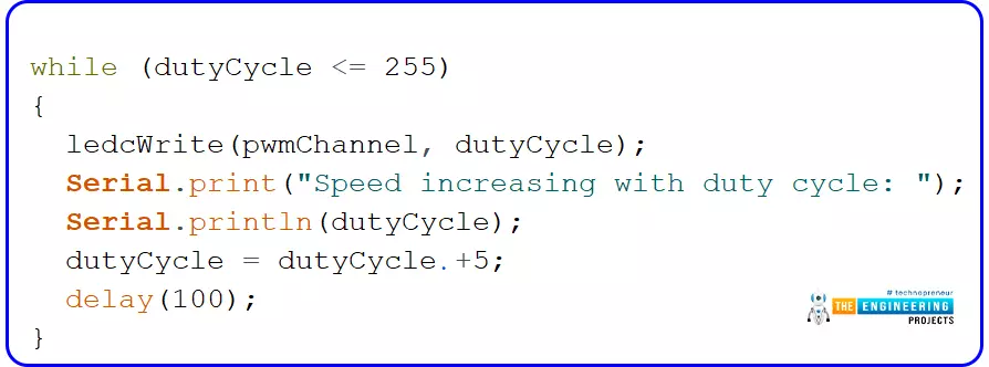
Fig. 21 Increasing speed
- After reaching the maximum speed at 255 duty cycle, now let's decrease the speed of DC motor till 150 duty cycle with the decrease of 5 steps every time.
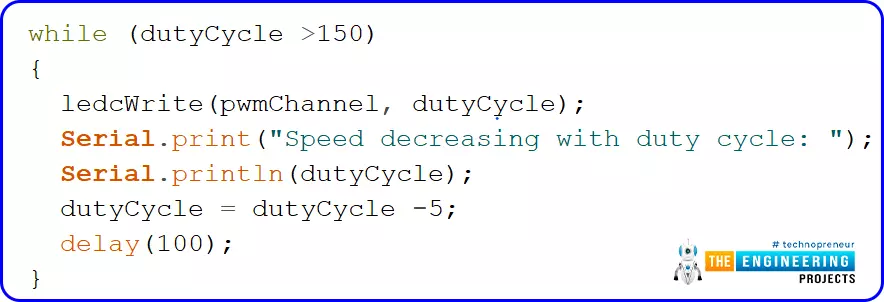
Fig. 22 Reducing speed
- Stop duty cycle by either writing both the motor pins(M_Pin1, M_Pin2) to LOW or HIGH (like XOR gate).
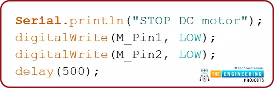
Fig. 23 STOP DC motor
Code Testing
- For a better understanding, open the serial monitor using shortcut keys ctrl+shift+M.
- On the serial monitor, you can see the increase and decrease in duty cycle and can compare it with DC motor speed.
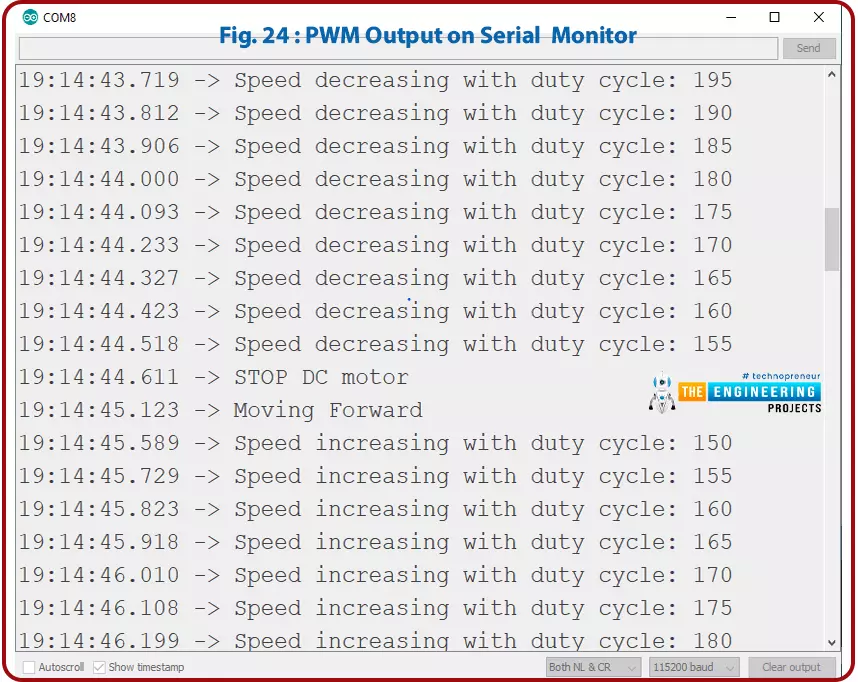
Fig. 24 PWM output on serial monitor
- You can also check the PWM output on the Serial plotter by pressing the ctrl+shift+L keys.
- It is visible through the waveform that the duty cycle is varying from 150 to 255 and reverse and proportionally the seed of the DC motor.
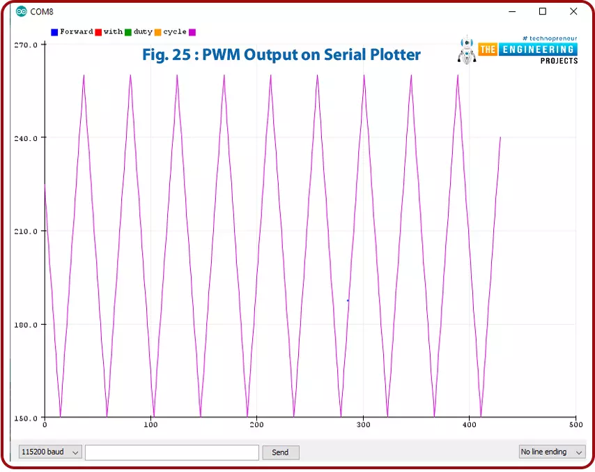
Fig. 25 PWM output on Serial Plotter
This concludes the tutorial. I hope you found this useful, and I hope to see you soon for the new ESP32 tutorial.