ESP32 Hall Effect Sensor in Arduino IDE


Hello readers, I hope you all are doing great. Welcome to Section 5 of the ESP32 Programming Series. In this section, we are going to interface different Embedded Sensors with the ESP32 Microcontroller Board. ESP32 development board is featured with some inbuilt sensors(i.e. hall effect sensor, capacitive touch sensor) so, in the initial tutorials of this section, we will explore these built-in ESP32 sensors and in the later lectures, we will interface third-party sensors with the ESP32.
In today's lecture, we will discuss the working/operation of the ESP32 built-in Hall Effect Sensor. Hall Effect sensor is used to detect the variation in the magnetic field of its surroundings. So, let's first understand What's Hall Effect:
What is the Hall Effect?
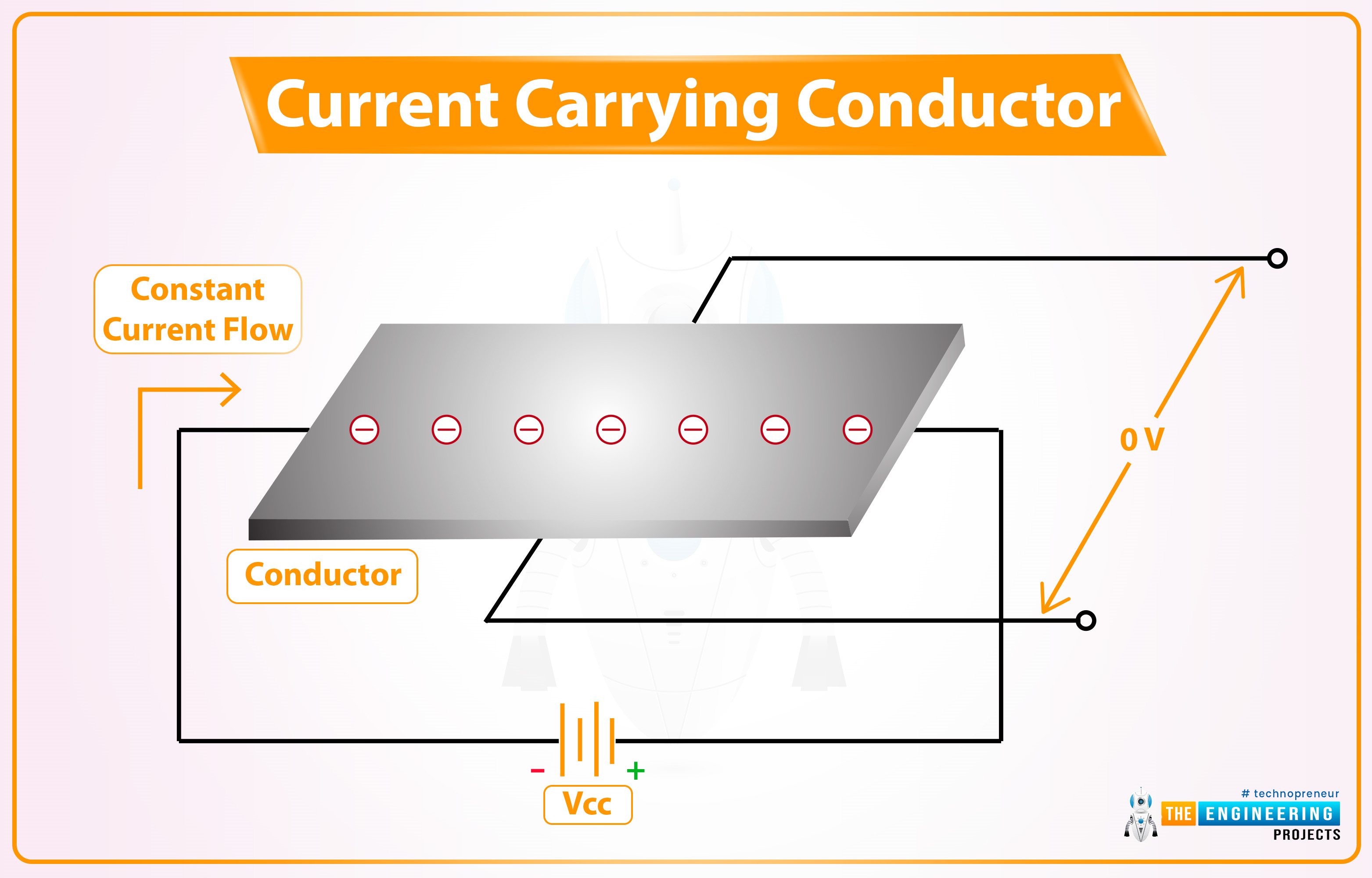
The Hall Effect phenomenon was first discovered by Edwin Hall in 1879. When current passes through a conductor, the electrons move in a straight line and thus the voltage difference across the conductor's surface remains zero, as shown in the below figure:
However, when a magnet is placed near the current-carrying conductor in a way that the direction of the magnetic field is perpendicular to the flow of current, the electrons get diverted and don't follow a straight line, which results in generating a small potential difference across the conductor's surface, as shown in the below figure:
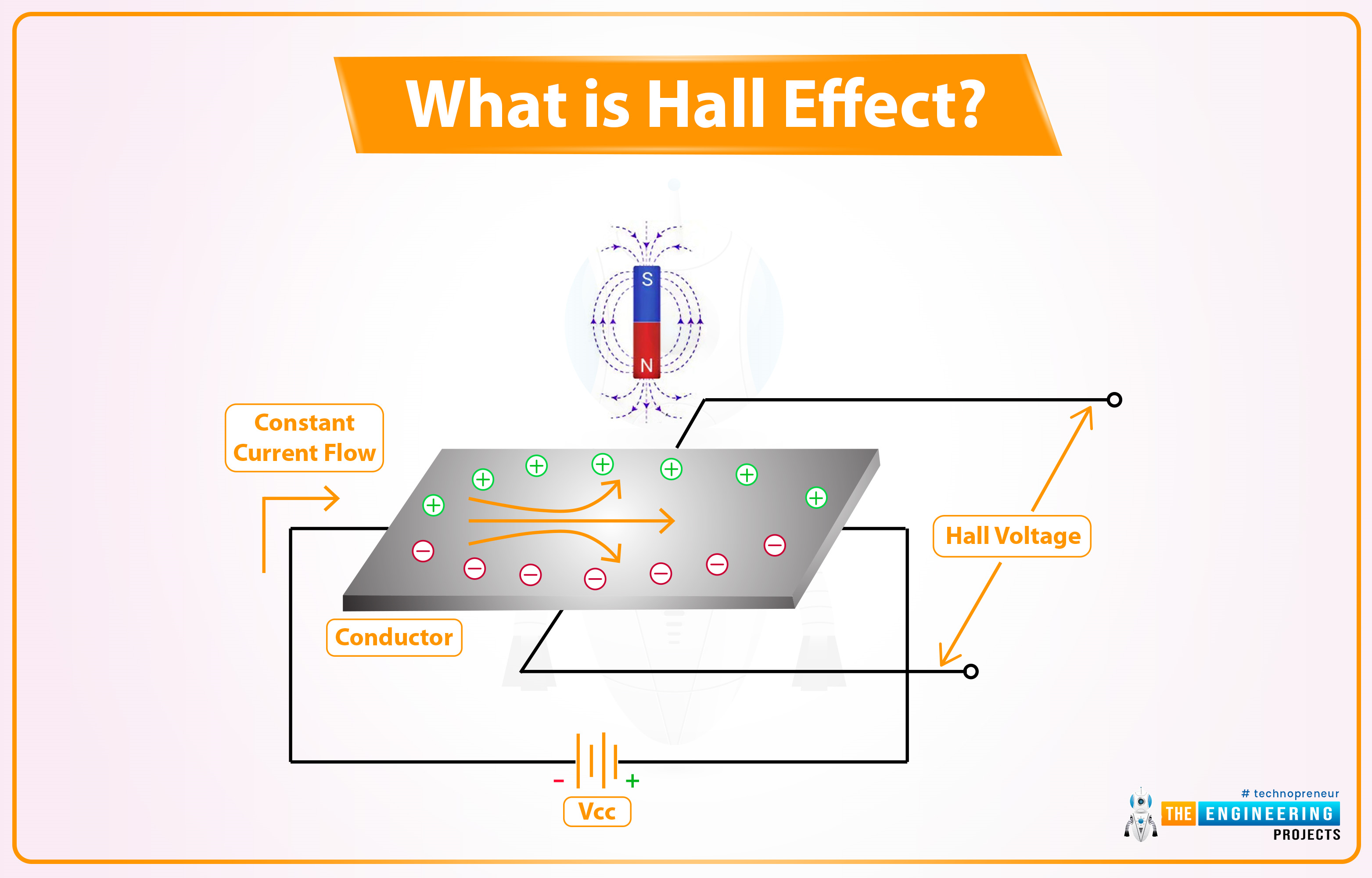
This small potential difference generated because of magnetic field presence is called Hall Voltage. This magnetic field influence over the current-carrying conductor is termed the Hall Effect.
Hall Effect Sensor
A Hall Effect Sensor is a non-contact type embedded sensor, used to detect the presence & intensity of a magnetic field in its surroundings. Different third-party Hall Effect Sensors available in the market are shown in the below figure:
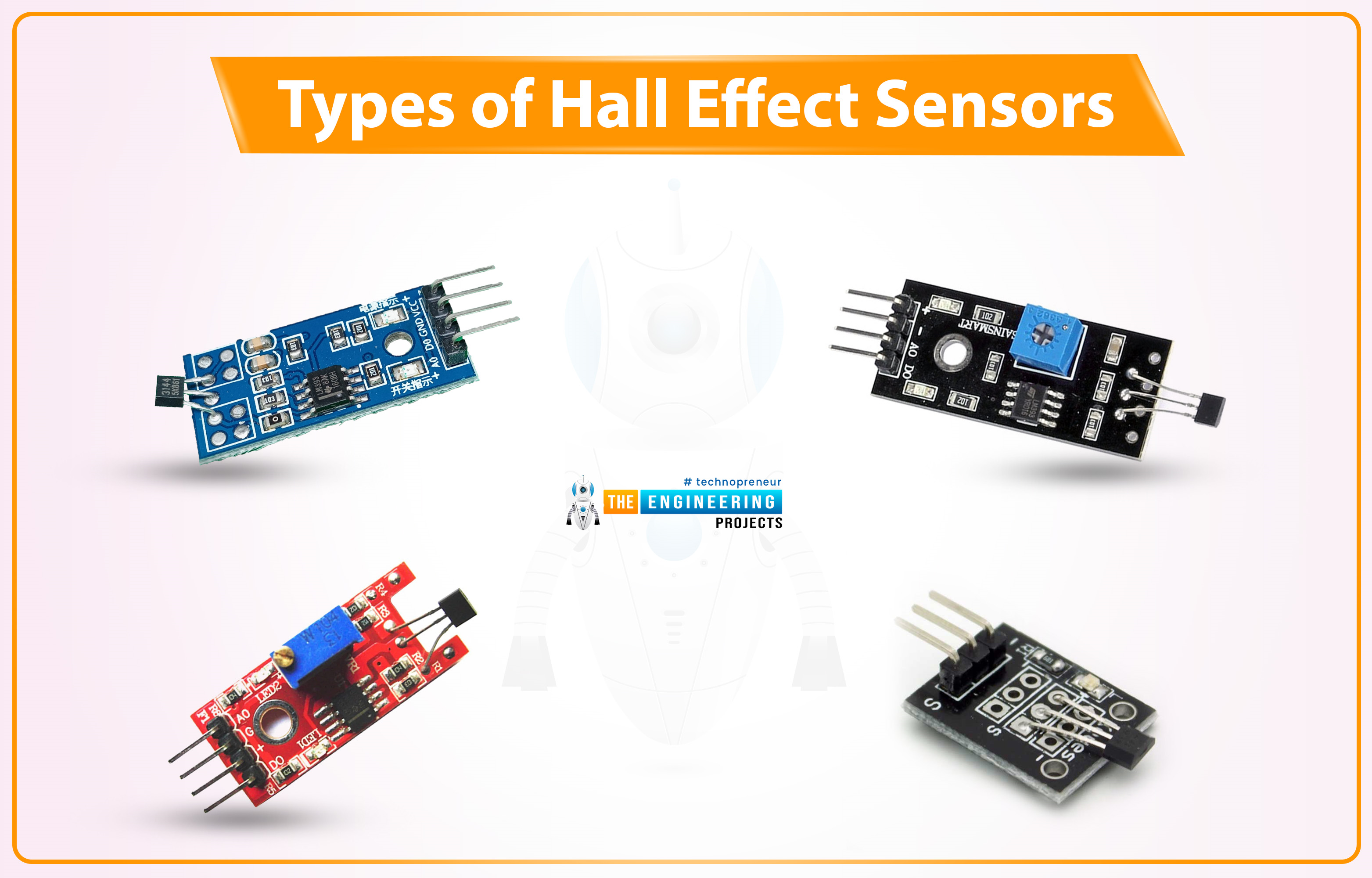
- A normal Hall Effect Sensor Pinout consists of 3 Pins i.e.
- Vcc: Normally +5V, few +3.3V are also available.
- GND: We need to provide Ground here.
- OUT: The Output Pin to give the sensor's response.
- When a perpendicular magnetic field is placed near a Hall-effect sensor, it changes the status of its Output Pin.
- The analog Hall Effect Sensors can also detect the strength of the magnetic field i.e. greater the magnetic field greater will be the sensor's output or voltage deviation.
Applications of Hall Effect sensor
- In an Automotive system, Hall Sensors are used to detect speed, distance, position etc.
- Used in Proximity sensing.
- Used in Current sensing.
- Used in Anti-lock braking system.
- Used in Internal combustion engines to assist with ignition timing.
- To switch an electric circuit ON and OFF.
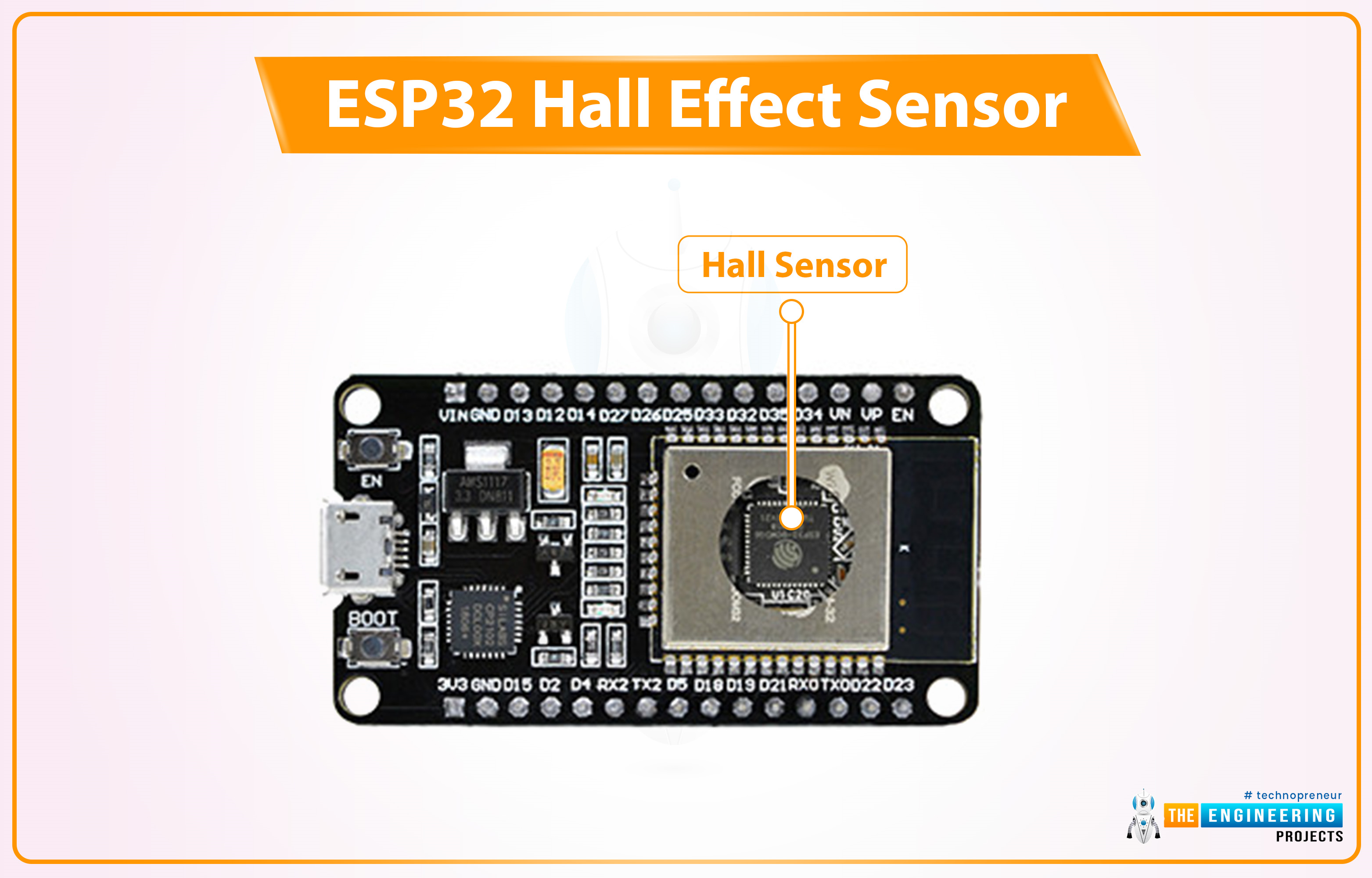
Hall Effect Sensor in ESP32
In ESP32, the Hall effect sensor is located inside the ESP-WROOM-32 metallic cover. As the Hall Effect sensor is a non-contact type, it doesn't have to be in contact with the magnet. We just need to place the magnet above this metallic sheet and the ESP32 Hall Effect sensor will detect it.
Programming ESP32 Hall Effect Sensor using Arduino IDE
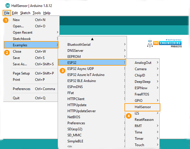
To understand the working of the Hall sensor with ESP32, let's test the builtin ESP32 example:
- You can find the code through File> Examples> ESP32 > Hall Sensor, as shown in the below figure:
Arduino IDE code
Here's the code for this ESP32 Hall Sensor example:
int val = 0;

void setup()
{
   Serial.begin (9600);
}

void loop()
{
   val = hallRead();
   Serial.print ("sensor value = ");
   Serial.println (val);//to graph

   delay(100);
}
Code Description
The code is quite simple, where the hallRead() function is called to read the hall sensor value, store it into a variable and then print it on the Serial monitor. Finally added a small delay to get the next value. Let me explain the code line by line for the beginners:
Variables Declaration
- The first step will be the declaration of an integer-type variable to store the hall sensor value. The initial value assigned to the variable is zero.
int val = 0;Setup() Function
- Inside the setup function, the only task is to initialize the serial port at a 9600 baud rate for serial communication.
void setup()
{
   Serial.begin (9600);
}
Loop() Function
- Inside the loop function, we called a function ‘hallRead()’ to read the sensor value and store those readings into the variable ‘val’.
- Printed the sensor readings on the serial monitor or serial plotter using serial.println() function.
- A delay of 0.3 sec is added at the end.
void loop()
{
   val = hallRead();
   Serial.print ("sensor value = ");
   Serial.println (val);//to graph

   delay(100);
}
ESP32 Hall Effect Sensor - Testing
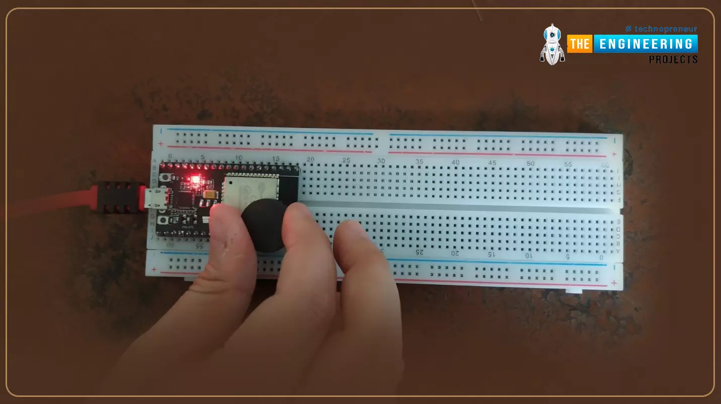
- After successfully uploading the code into ESP32, open the serial plotter or serial monitor to monitor the results.
- Place a magnet near the ESP32 board.
- The sensor reading will increase/decrease depending on the magnet pole(i.e. North or South Pole) facing the Hall sensor.
- Now click on Tools > Serial Plotter to visually analyze the sensor's output.
- The Serial Plotter of our project is shown in the below figure:
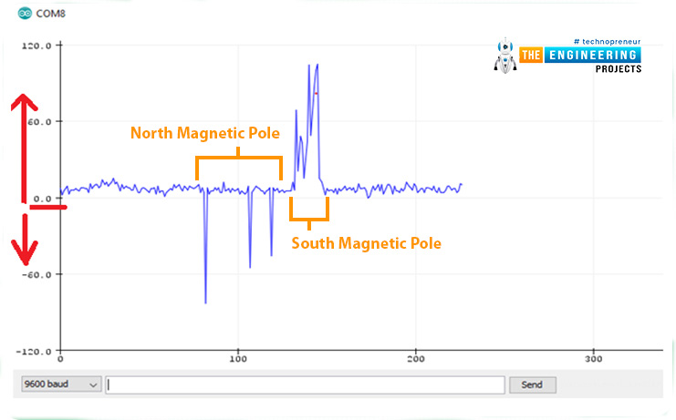
- As you can see in the above figure, the sensor is giving negative output when facing the North Pole of the magnet.
- In the case of a South Pole, the sensor's output is positive.
- In the absence of a magnetic field, the sensor's output is almost 0.
- The distance between the magnet and the Hall sensor decides the amount of potential difference generated.
- The greater the distance between the two, the smaller the hall voltage or potential difference will be.
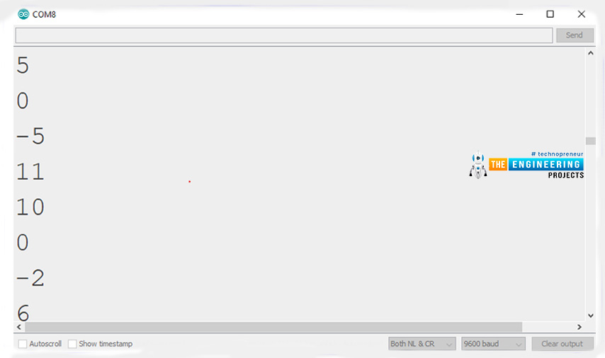
- We have attached an image from the Arduino IDE serial monitor for your reference.
This concludes the tutorial. I hope you found this helpful, test it out and if feel any difficulty, let me know in the comments. In the next tutorial, we will have a look at another built-in sensor of ESP32 i.e. Capacitive Touch Sensor. Thanks for reading.