Simulating advanced logic gate, NAND logic gate, The NANA ladder logic in two ways, NAND ladder logic when both inputs are false, NAND ladder logic when input A is false and input B is true, NAND ladder logic when input A is true and input B is false, NAND ladder logic when both inputs are true, NOR logic gate, XOR logic gate, XNOR logic gate, XNOR ladder logic when input A is true and input B is false, XNOR ladder logic when input A is false and input B is true
Hello friends! I hope you are all very well! I am so happy to meet you today to continue learning and practicing PLC ladder logic programming. In an earlier part, we already have gone through the very basic logic gates of “AND”. “OR”, and “NOT”. Today we are going to resume the simulation of logic gates. We have started and gone through simulating the basic logic gates which are “AND”, “OR”, and “NOT” as they are the most important basic logic gates by which we can form other logic gates. However, because the logic of large-scale projects is getting more and more complicating, a lot of time we have to use the other functions to do tasks faster. For example, we have shown in the logic gates article that, XOR can be used to compare two inputs and check if they are equal or not. On the other hand, someone may say, oh we can do XOR by using the basic three gates of “AND”, “OR”, and “NOT”. That’s correct. So why do we need to go learning other logic gates when we can implement them by using that three basic logic gates. Well! That is a very good question.

Working in ladder logic programs is getting further complicated especially for large-scale projects. So, it is very beneficial to know shortcuts for writing ladder logic simpler, more readable, and easier for others to develop. Using this variety of logic gates, enrich the logic and fluency of writing the logic in different situations. For example, using XOR logic is very common for comparing two inputs to decide if they are equal or different. Therefore, we found that it is crucial to go through all logic gates and do simulations for them all in this tutorial. for coherently we get the knowledge to use them fluently in ladder logic programming to solve different logical problems and scenarios. There are seven basic logic gates which are: “AND”, “OR”, “NOT”, “NAND”, “NOR”, “XOR”, and “XNOR”. We have gone through “AND”, “OR”, and “NOT” logic gates including simulation work. So let us go through the other four gates for learning and practicing all basic logic gates.

The "NAND" Logic Gate

The “NAND” logic gate is the invert of the “AND” gate like you invert the output of an “AND” logic gate as shown in Fig. 12. Table 5 lists all combinations of the inputs and the output of the “NAND” logic gate.

Play with logic gates, Logic gates, Truth table, Basics of logic gate, The AND logic gate, The OR logic gate, The NOT logic gate, NAND logic gate, NOR logic gate, XNOR logic gate, Next logic gate

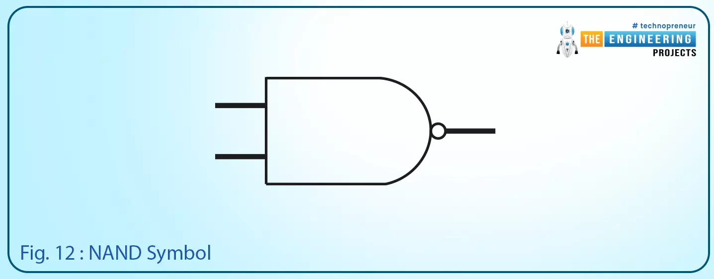
Fig. 12: NAND symbol

Play with logic gates, Logic gates, Truth table, Basics of logic gate, The AND logic gate, The OR logic gate, The NOT logic gate, NAND logic gate, NOR logic gate, XNOR logic gate, Next logic gate

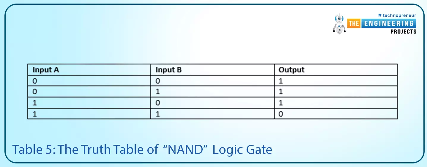
Table 5: the truth table of the “NAND” logic gate

Input A Input B Output
0 0 1
0 1 1
1 0 1
1 1 0
 

In addition, the timing diagram of a “NAND” logic gate is shown in fig. 13, it shows the output goes low when both of the inputs A and B are true which is the inverse of the “AND” logic gate. Also, Fig. 14 shows a ladder logic of a “NAND” logic.

Play with logic gates, Logic gates, Truth table, Basics of logic gate, The AND logic gate, The OR logic gate, The NOT logic gate, NAND logic gate, NOR logic gate, XNOR logic gate, Next logic gate

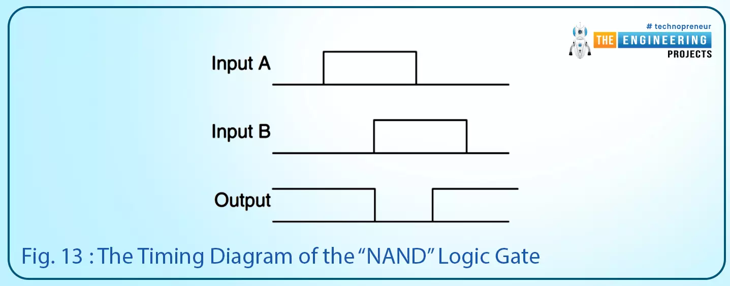
Fig. 13: The timing diagram of the “NAND” logic gate

Play with logic gates, Logic gates, Truth table, Basics of logic gate, The AND logic gate, The OR logic gate, The NOT logic gate, NAND logic gate, NOR logic gate, XNOR logic gate, Next logic gate

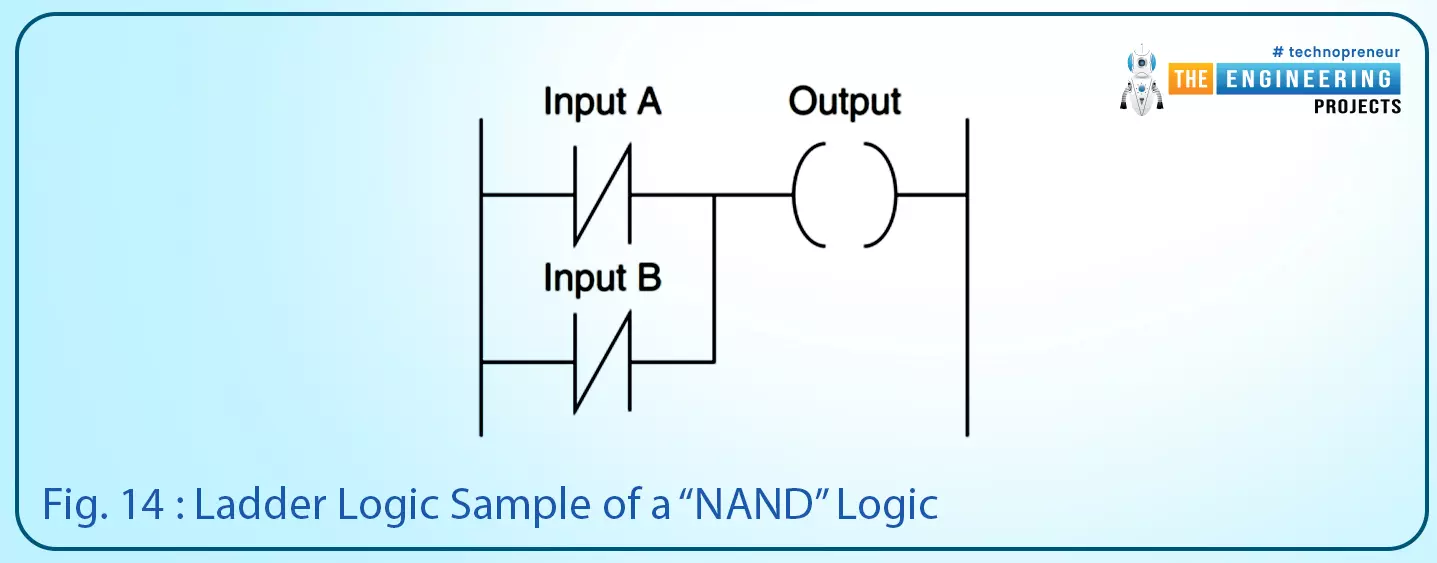
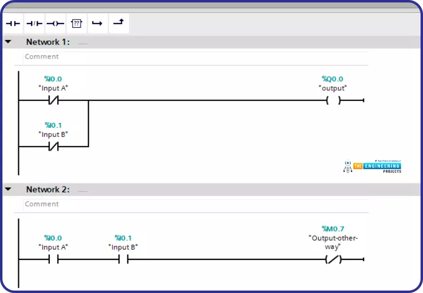
Fig. 14: Ladder logic sample of a “NAND” logic

NAND Logic in PLC simulator

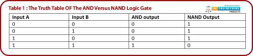
The NAND logic gate can be considered as the invert of the “AND” logic gate. So as listed in table 1, the truth table of AND and NAND logic gates shows how the NAND gate is the reverse of the AND gate. Also, it shows the NAND gate should come out to your mind when you want the output always low except when both inputs A and B are high.

Simulating advanced logic gate, NAND logic gate, The NANA ladder logic in two ways, NAND ladder logic when both inputs are false, NAND ladder logic when input A is false and input B is true, NAND ladder logic when input A is true and input B is false, NAND ladder logic when both inputs are true, NOR logic gate, XOR logic gate, XNOR logic gate, XNOR ladder logic when input A is true and input B is false, XNOR ladder logic when input A is false and input B is true
Table 1: the truth table of the AND versus NAND logic gate

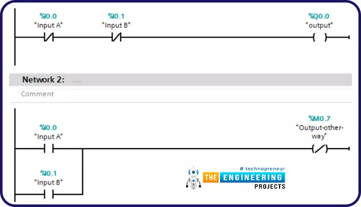
The NAND gate can be implemented by connecting the negate of the output in series to the inputs A and B. Another way to implement NAND is by inverting both inputs and connecting them in parallel as shown in fig. 1. Rung 1 and rung 2 respectively.

Simulating advanced logic gate, NAND logic gate, The NANA ladder logic in two ways, NAND ladder logic when both inputs are false, NAND ladder logic when input A is false and input B is true, NAND ladder logic when input A is true and input B is false, NAND ladder logic when both inputs are true, NOR logic gate, XOR logic gate, XNOR logic gate, XNOR ladder logic when input A is true and input B is false, XNOR ladder logic when input A is false and input B is true

Fig. 1: The NAND ladder logic in two ways


Let’s test our ladder logic in both methods. According to the truth table of NAND gate, we have four test cases. figure 2 shows the first test case when both inputs A and B are false. In this case, the output should be true as shown in fig. 1.

Simulating advanced logic gate, NAND logic gate, The NANA ladder logic in two ways, NAND ladder logic when both inputs are false, NAND ladder logic when input A is false and input B is true, NAND ladder logic when input A is true and input B is false, NAND ladder logic when both inputs are true, NOR logic gate, XOR logic gate, XNOR logic gate, XNOR ladder logic when input A is true and input B is false, XNOR ladder logic when input A is false and input B is true

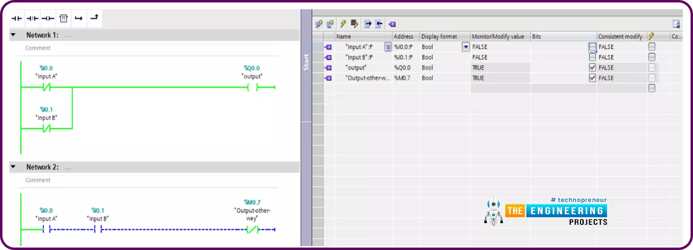
Fig. 2: NAND ladder logic when both inputs are false

figure 3 shows the second test case when inputs A goes true while B is false. In this case, the output should be true as shown in fig. 3.

Simulating advanced logic gate, NAND logic gate, The NANA ladder logic in two ways, NAND ladder logic when both inputs are false, NAND ladder logic when input A is false and input B is true, NAND ladder logic when input A is true and input B is false, NAND ladder logic when both inputs are true, NOR logic gate, XOR logic gate, XNOR logic gate, XNOR ladder logic when input A is true and input B is false, XNOR ladder logic when input A is false and input B is true
Fig. 3: NAND ladder logic when input A is false and input B is true

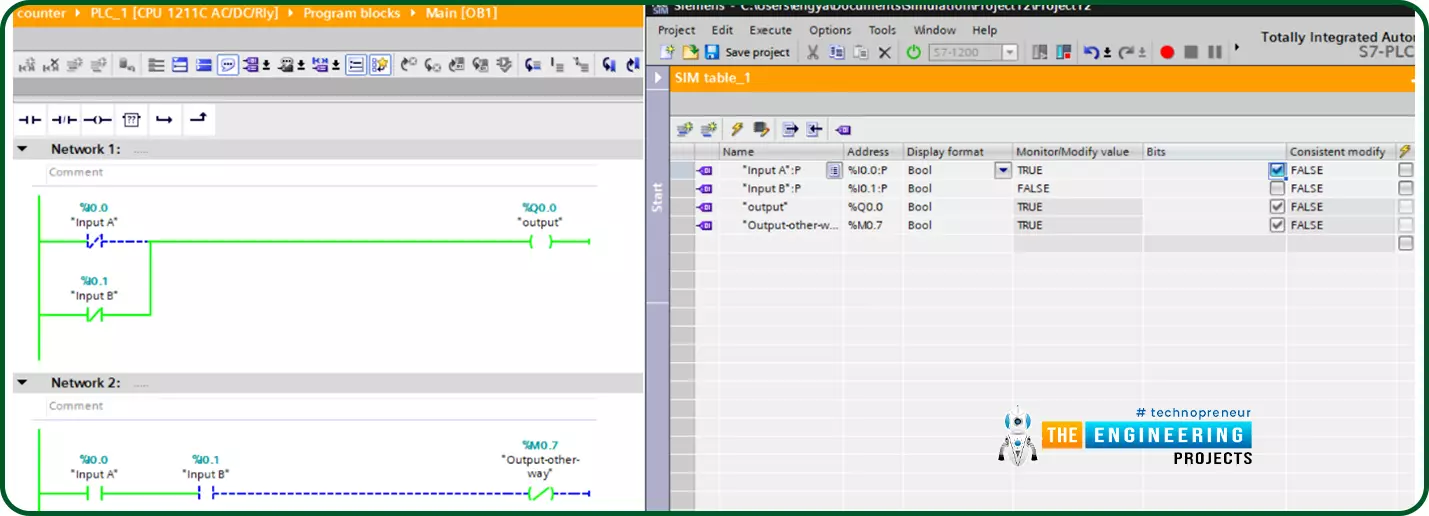
Figure 4 shows the third test case when inputs B goes high while B is low. In this case, the output should be true as shown in fig. 4.

Simulating advanced logic gate, NAND logic gate, The NANA ladder logic in two ways, NAND ladder logic when both inputs are false, NAND ladder logic when input A is false and input B is true, NAND ladder logic when input A is true and input B is false, NAND ladder logic when both inputs are true, NOR logic gate, XOR logic gate, XNOR logic gate, XNOR ladder logic when input A is true and input B is false, XNOR ladder logic when input A is false and input B is true

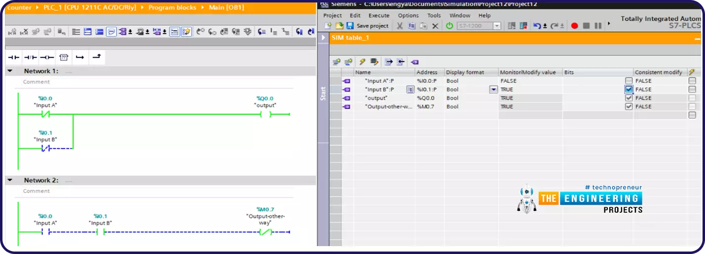
Fig. 4: NAND ladder logic when input A is true and input B is false

Figure 5 shows the last test case when both inputs A and B become high so the output goes false as shown in fig. 5.

Simulating advanced logic gate, NAND logic gate, The NANA ladder logic in two ways, NAND ladder logic when both inputs are false, NAND ladder logic when input A is false and input B is true, NAND ladder logic when input A is true and input B is false, NAND ladder logic when both inputs are true, NOR logic gate, XOR logic gate, XNOR logic gate, XNOR ladder logic when input A is true and input B is false, XNOR ladder logic when input A is false and input B is true

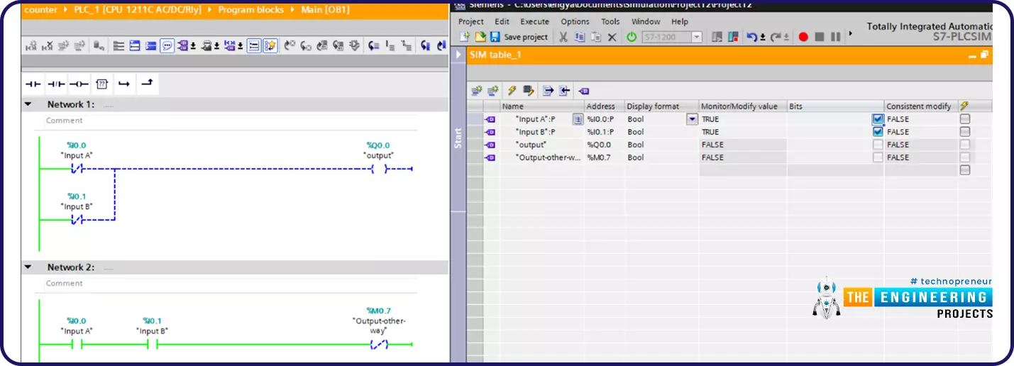
Fig. 5: NAND ladder logic when both inputs are true

Thanks to performing the simulation of the NAND gate, we now can conclude that we should be looking for a NAND logic when we want to shut down an actuator i.e. motor whenever two inputs are in a true logical state simultaneously. For a practical example, when we have three pumps and we want to run them in the mode of two of three. There should be only two of the three pumps to run at any time. In that case scenario, the run condition of any motor can be a NAND of the status of the other two motors.

The “NOR” Logic Gate

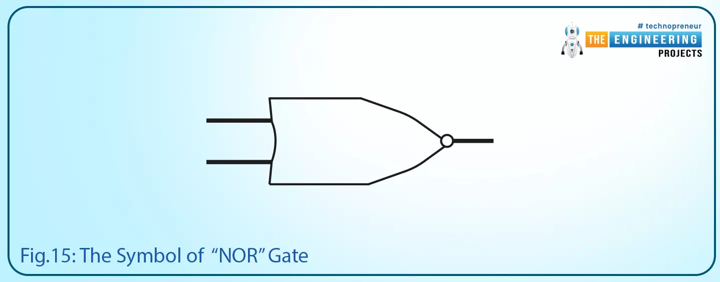
The “NOR” logic gate receives two inputs and has one output. It is the same as the invert of the “OR” logic gate. Like you follow the output of an “OR” gate by a “NOT” logic gate. Fig. 15 shows the symbol of a “NOR” gate. In addition, the truth table is expressed in table 6. It shows the output becomes false only when one of the input A or input B or both goes high which is the reverse logic of the “OR” logic gate.

Play with logic gates, Logic gates, Truth table, Basics of logic gate, The AND logic gate, The OR logic gate, The NOT logic gate, NAND logic gate, NOR logic gate, XNOR logic gate, Next logic gate
Fig. 15: The symbol of “NOR” gate

The “NOR” logic gate can be formed by connecting the “OR” logic gate to the inverter “NOT” logic gate. Or by inverting the inputs by using “NOT” logic gates and connecting them to the “AND” logic gate as shown in Fig. 16.

Play with logic gates, Logic gates, Truth table, Basics of logic gate, The AND logic gate, The OR logic gate, The NOT logic gate, NAND logic gate, NOR logic gate, XNOR logic gate, Next logic gate

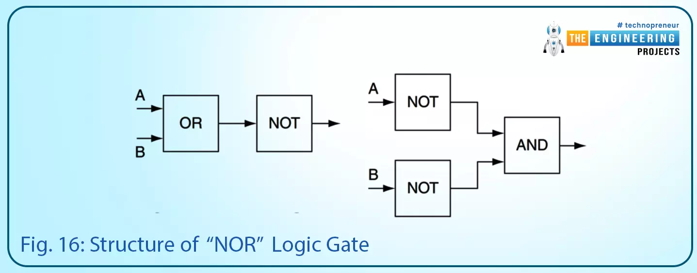
Fig. 16: structure of “NOR” logic gate

Play with logic gates, Logic gates, Truth table, Basics of logic gate, The AND logic gate, The OR logic gate, The NOT logic gate, NAND logic gate, NOR logic gate, XNOR logic gate, Next logic gate

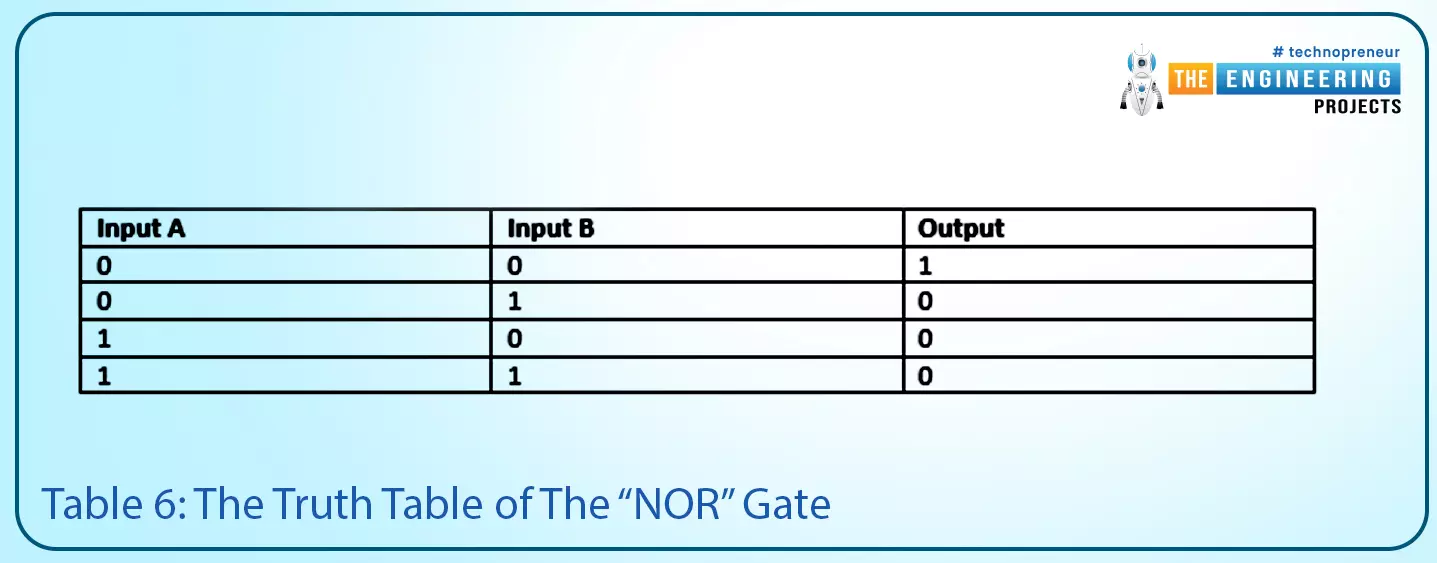
Table 6: the truth table of the “NOR” gate

Input A Input B Output
0 0 1
0 1 0
1 0 0
1 1 0
 

Figure 17 shows an example of a ladder program for implementing the “NOR” logic gate. It shows that the “NOR” gate can be implemented in ladder logic by connecting two contacts of type NC in series.

Play with logic gates, Logic gates, Truth table, Basics of logic gate, The AND logic gate, The OR logic gate, The NOT logic gate, NAND logic gate, NOR logic gate, XNOR logic gate, Next logic gate

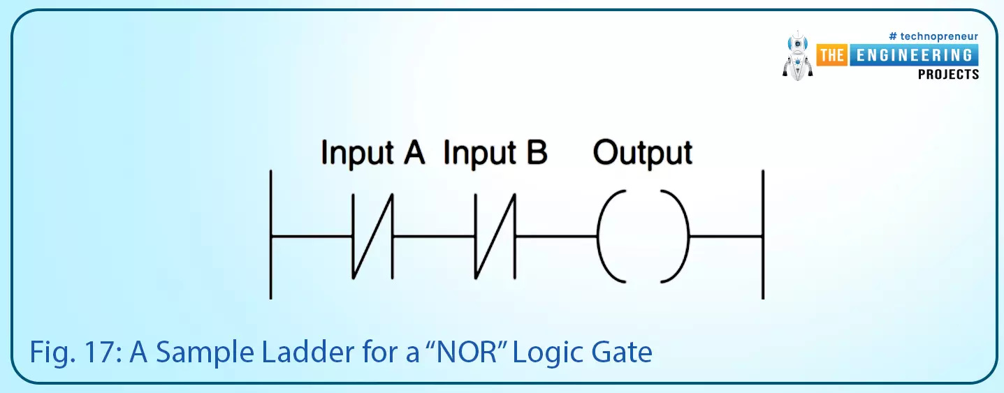
Fig. 17: A sample ladder for a “NOR” logic gate

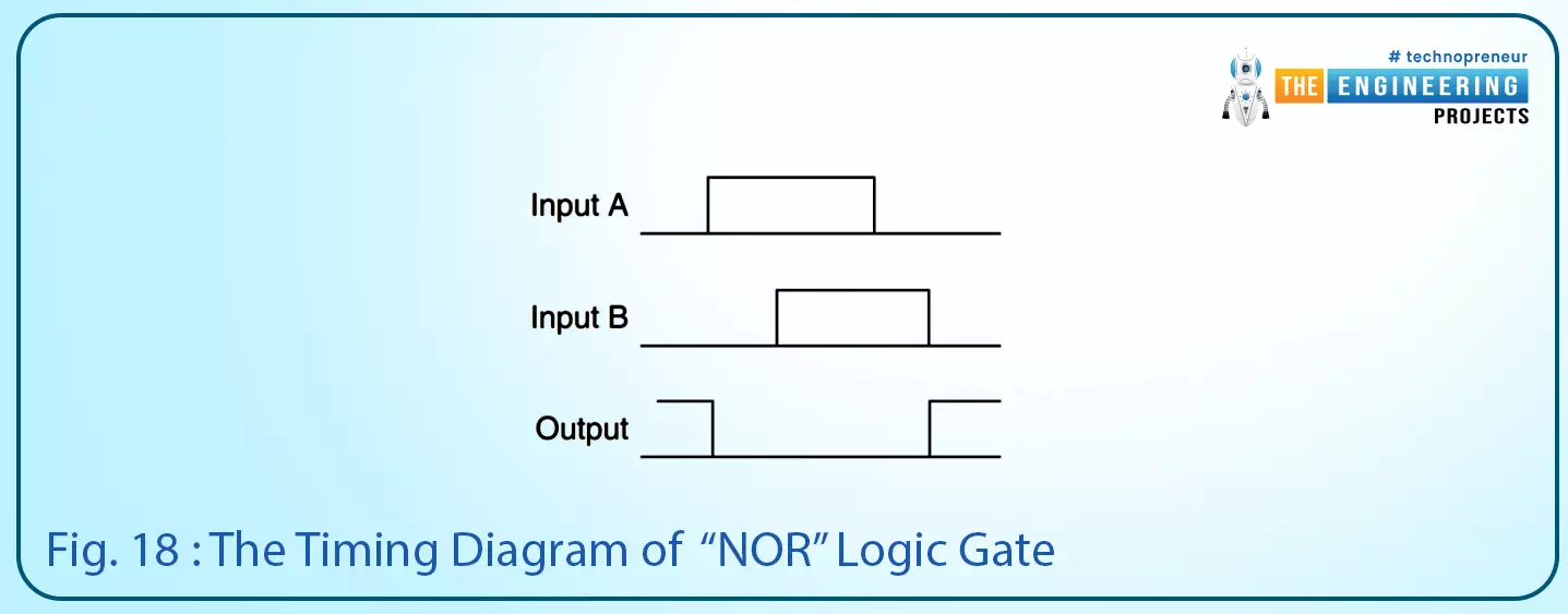
On the other hand, the timing diagram of the “NOR” logic gate is depicted in Fig. 18. It shows the output is false as long as either input A or input B or both are true.

Play with logic gates, Logic gates, Truth table, Basics of logic gate, The AND logic gate, The OR logic gate, The NOT logic gate, NAND logic gate, NOR logic gate, XNOR logic gate, Next logic gate
Fig. 18: The timing diagram of the “NOR” logic gate

NOR logic gate in PLC Simulator

This logic gate can be considered as the negate of OR as you can notice in the truth table as listed in table 2. You can now feel when we may need to use the NOR logic? Yes! Exactly you want it when you design for output which is all time off except when both inputs are false.

Simulating advanced logic gate, NAND logic gate, The NANA ladder logic in two ways, NAND ladder logic when both inputs are false, NAND ladder logic when input A is false and input B is true, NAND ladder logic when input A is true and input B is false, NAND ladder logic when both inputs are true, NOR logic gate, XOR logic gate, XNOR logic gate, XNOR ladder logic when input A is true and input B is false, XNOR ladder logic when input A is false and input B is true

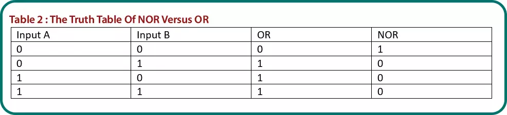
Table 2: the truth table of NOR versus OR

Input A Input B OR NOR
0 0 0 1
0 1 1 0
1 0 1 0
1 1 1 0
 

Figure 6 shows two ways to implement the NOR logic in ladder logic. To make that happen, we connect the invert of the two inputs in series to the output as shown in the top part of fig. 6. The other way is to connect the two inputs in parallel to form OR and then connect to negate the output as shown in the lower part of fig. 6.

Simulating advanced logic gate, NAND logic gate, The NANA ladder logic in two ways, NAND ladder logic when both inputs are false, NAND ladder logic when input A is false and input B is true, NAND ladder logic when input A is true and input B is false, NAND ladder logic when both inputs are true, NOR logic gate, XOR logic gate, XNOR logic gate, XNOR ladder logic when input A is true and input B is false, XNOR ladder logic when input A is false and input B is true
Fig. 6: The ladder logic of NOR logic gate

Let’s practice simulation of the NOR gate, in fig. 7, the first test case is when both inputs are false, the output is true as shown in fig. 7.

Simulating advanced logic gate, NAND logic gate, The NANA ladder logic in two ways, NAND ladder logic when both inputs are false, NAND ladder logic when input A is false and input B is true, NAND ladder logic when input A is true and input B is false, NAND ladder logic when both inputs are true, NOR logic gate, XOR logic gate, XNOR logic gate, XNOR ladder logic when input A is true and input B is false, XNOR ladder logic when input A is false and input B is true

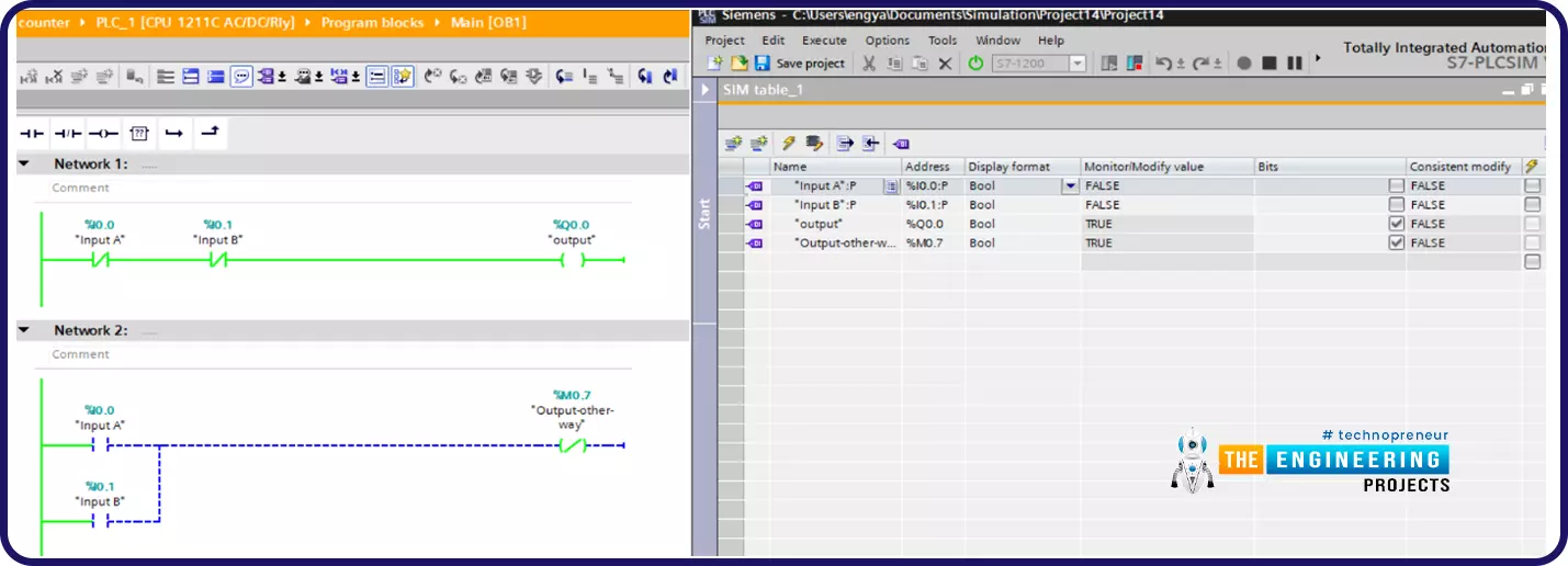
Fig. 7: The Simulation of NOR ladder when both inputs are false

Figure 8 shows the second case when input A is true and input B is false, the output is false as shown in fig. 8.

Simulating advanced logic gate, NAND logic gate, The NANA ladder logic in two ways, NAND ladder logic when both inputs are false, NAND ladder logic when input A is false and input B is true, NAND ladder logic when input A is true and input B is false, NAND ladder logic when both inputs are true, NOR logic gate, XOR logic gate, XNOR logic gate, XNOR ladder logic when input A is true and input B is false, XNOR ladder logic when input A is false and input B is true

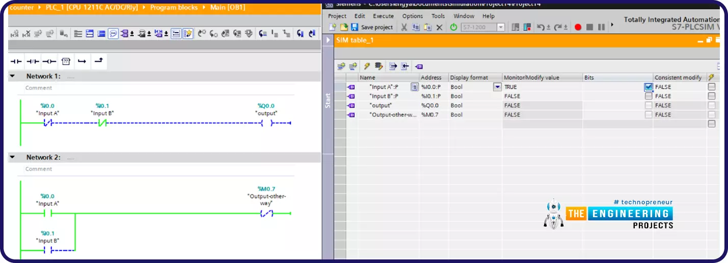
Fig. 8: The Simulation of NOR ladder when input A is true and input B is false

Figure 9 shows the third test case when input B is true and input A is false, the output is false as shown in fig. 9.

Simulating advanced logic gate, NAND logic gate, The NANA ladder logic in two ways, NAND ladder logic when both inputs are false, NAND ladder logic when input A is false and input B is true, NAND ladder logic when input A is true and input B is false, NAND ladder logic when both inputs are true, NOR logic gate, XOR logic gate, XNOR logic gate, XNOR ladder logic when input A is true and input B is false, XNOR ladder logic when input A is false and input B is true

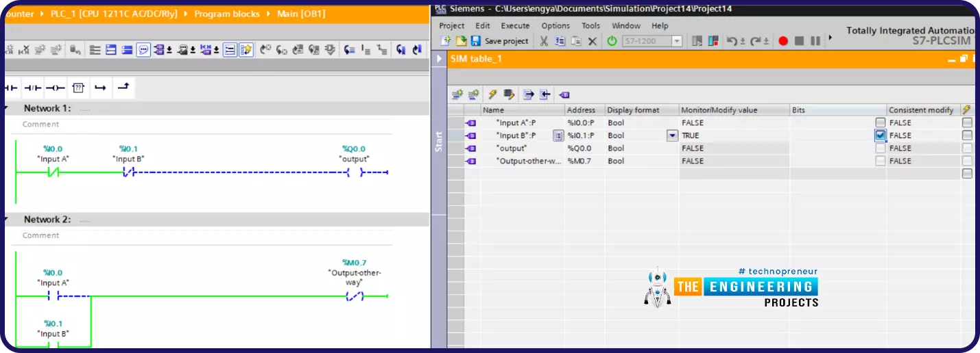
Fig. 9: the Simulation of NOR ladder when input B is true and input A is false

Figure 10 shows the last test case of NOR ladder logic, it shows the output is false

Simulating advanced logic gate, NAND logic gate, The NANA ladder logic in two ways, NAND ladder logic when both inputs are false, NAND ladder logic when input A is false and input B is true, NAND ladder logic when input A is true and input B is false, NAND ladder logic when both inputs are true, NOR logic gate, XOR logic gate, XNOR logic gate, XNOR ladder logic when input A is true and input B is false, XNOR ladder logic when input A is false and input B is true
Fig. 10: The Simulation of NOR ladder when both input A and B are true

One practical example of using the NOR logic is that, imagine friends we drive some machine with two motors. And it is required to have at least one of them or both are running all the time otherwise alarm should be energized. The NOR logic is the best to manage that alarm to get energized if and only if both motors are off.

The Exclusive OR "XOR" Logic Gate

Despite this logic gate having two inputs and one output like the “AND” and “OR” logic gates, this logic gate is a bit more complicated than the previous logic gates. Table 4 lists the truth table including all combinations of the inputs and the output. By noticing the truth table of the XOR logic gate, you can see the output becomes low when the two inputs are equal like both are high or both are low. But the output goes high when there is a difference in the state of the two inputs. Imagine my friend, how much this logic gate is very beneficial for comparing two signals.
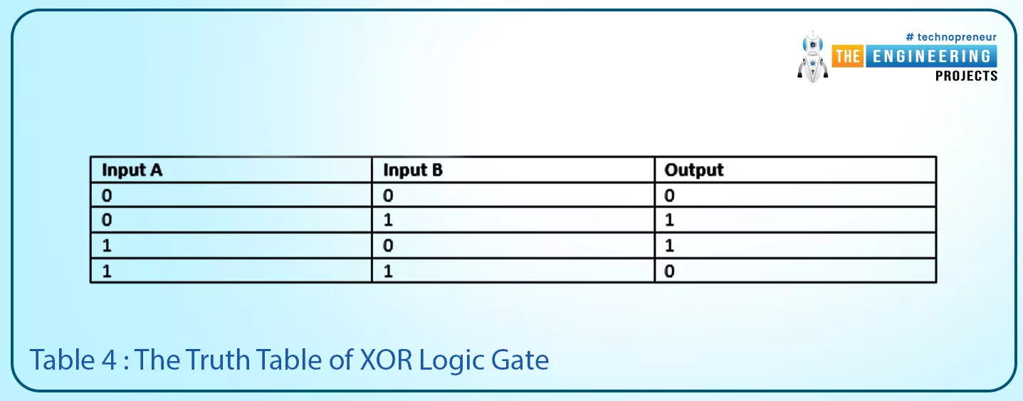
Play with logic gates, Logic gates, Truth table, Basics of logic gate, The AND logic gate, The OR logic gate, The NOT logic gate, NAND logic gate, NOR logic gate, XNOR logic gate, Next logic gate
Table 4: The truth table of XOR logic gate

Input A Input B Output
0 0 0
0 1 1
1 0 1
1 1 0
 

On the other hand, Figure 10 shows the symbol of the XOR logic gate and its schematic. See how the basic logic gates OR, AND, and NOT can be utilized to build the logic of XOR logic gate.

Play with logic gates, Logic gates, Truth table, Basics of logic gate, The AND logic gate, The OR logic gate, The NOT logic gate, NAND logic gate, NOR logic gate, XNOR logic gate, Next logic gate

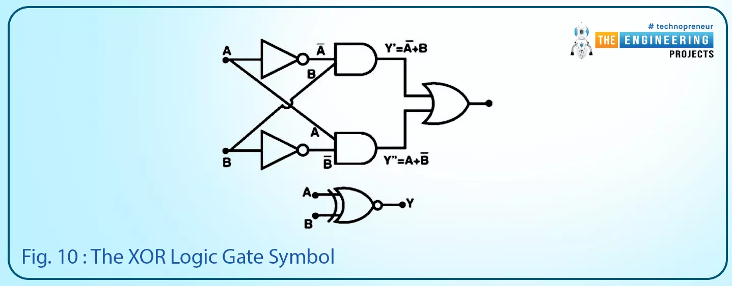
Fig. 10: The XOR logic gate symbol

Figure 11 shows a sample of a ladder logic program that implements XOR logic. In addition, it shows the timing diagram of the inputs and output, it shows the output goes high when there is a difference between the two inputs and becomes low when they are equal i.e. both are low or both are high.

Play with logic gates, Logic gates, Truth table, Basics of logic gate, The AND logic gate, The OR logic gate, The NOT logic gate, NAND logic gate, NOR logic gate, XNOR logic gate, Next logic gate

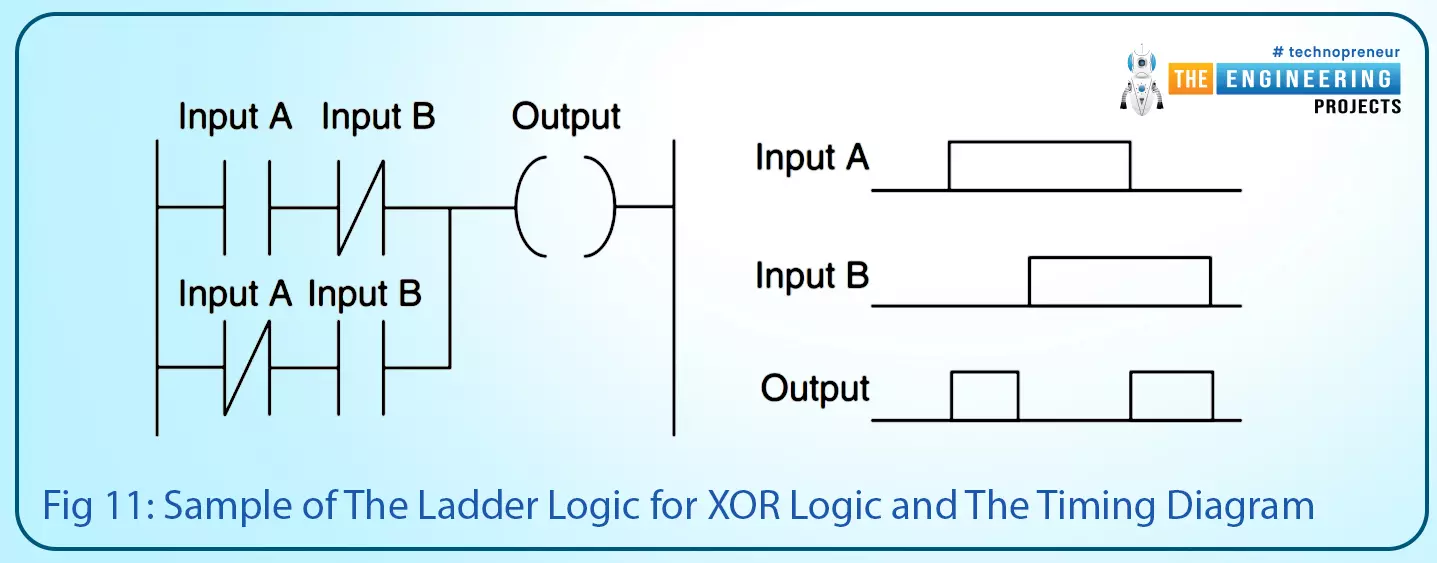
Fig 11: Sample of the ladder logic for XOR logic and the timing diagram

XOR Logic Gate in PLC Simulator

The XOR is used to compare two signals if they are equal or different. Table 3 lists the truth table of the XOR. It shows that the output comes to true when inputs are different and becomes false when they are equal.

Simulating advanced logic gate, NAND logic gate, The NANA ladder logic in two ways, NAND ladder logic when both inputs are false, NAND ladder logic when input A is false and input B is true, NAND ladder logic when input A is true and input B is false, NAND ladder logic when both inputs are true, NOR logic gate, XOR logic gate, XNOR logic gate, XNOR ladder logic when input A is true and input B is false, XNOR ladder logic when input A is false and input B is true

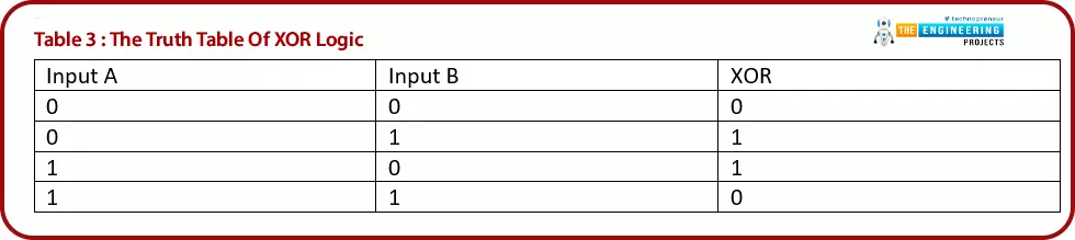
Table 3: The truth table of XOR logic

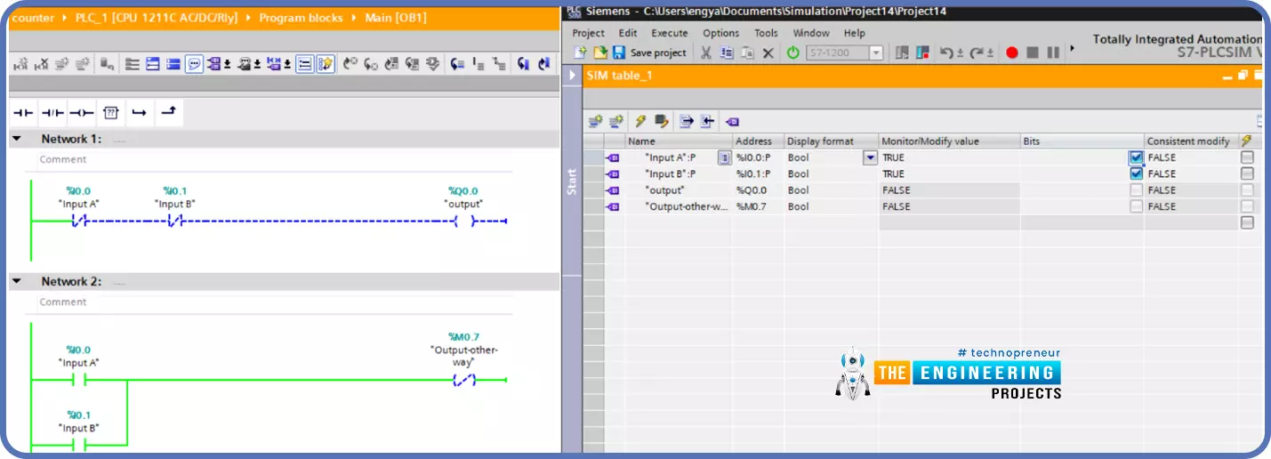
Figure 11 shows the construction of XOR ladder logic. It shows that it is composed of, two parallel branches and each branch is forming AND logic of the two inputs in the opposite logical state.

Simulating advanced logic gate, NAND logic gate, The NANA ladder logic in two ways, NAND ladder logic when both inputs are false, NAND ladder logic when input A is false and input B is true, NAND ladder logic when input A is true and input B is false, NAND ladder logic when both inputs are true, NOR logic gate, XOR logic gate, XNOR logic gate, XNOR ladder logic when input A is true and input B is false, XNOR ladder logic when input A is false and input B is true
Fig. 11: The ladder logic of XOR

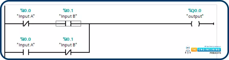
Figure 12, shows the simulation results of XOR when input A and B are false, the output is false.

Simulating advanced logic gate, NAND logic gate, The NANA ladder logic in two ways, NAND ladder logic when both inputs are false, NAND ladder logic when input A is false and input B is true, NAND ladder logic when input A is true and input B is false, NAND ladder logic when both inputs are true, NOR logic gate, XOR logic gate, XNOR logic gate, XNOR ladder logic when input A is true and input B is false, XNOR ladder logic when input A is false and input B is true
Fig 12: Simulation of XOR ladder when both inputs are false

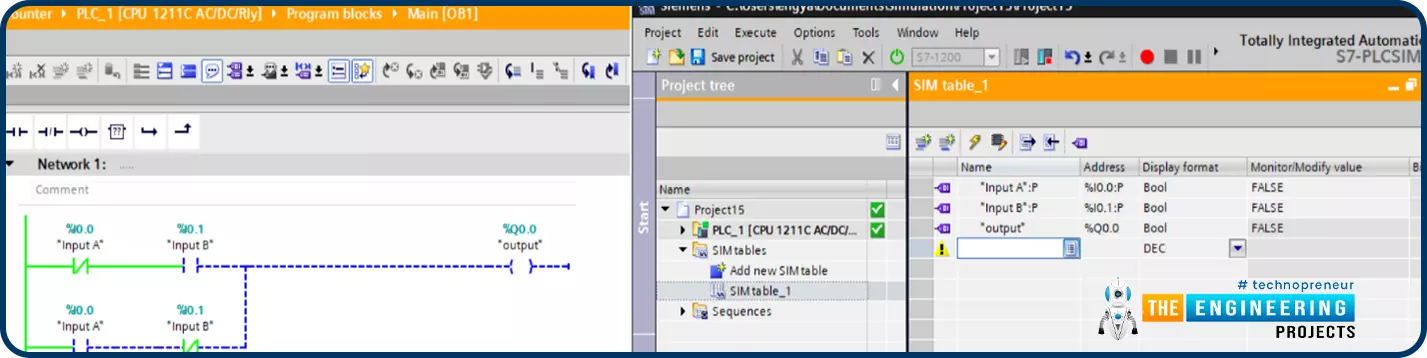
Figure 13, shows the simulation results of XOR when input A is true and input B is false, the output is true.

Simulating advanced logic gate, NAND logic gate, The NANA ladder logic in two ways, NAND ladder logic when both inputs are false, NAND ladder logic when input A is false and input B is true, NAND ladder logic when input A is true and input B is false, NAND ladder logic when both inputs are true, NOR logic gate, XOR logic gate, XNOR logic gate, XNOR ladder logic when input A is true and input B is false, XNOR ladder logic when input A is false and input B is true
Fig 13: The Simulation of XOR ladder when input A is false and input B is high

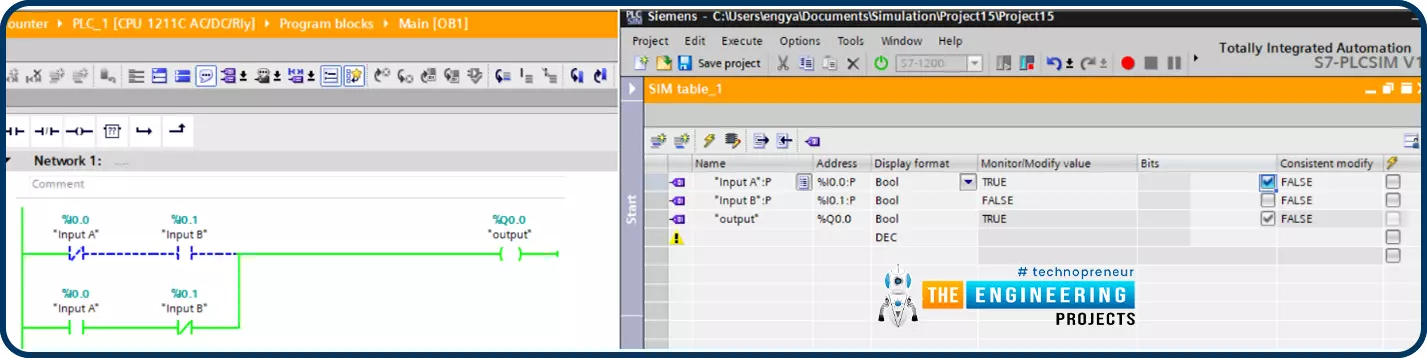
Figure 14, shows the simulation results of XOR when input B is true and input A is false, the output is true.

Simulating advanced logic gate, NAND logic gate, The NANA ladder logic in two ways, NAND ladder logic when both inputs are false, NAND ladder logic when input A is false and input B is true, NAND ladder logic when input A is true and input B is false, NAND ladder logic when both inputs are true, NOR logic gate, XOR logic gate, XNOR logic gate, XNOR ladder logic when input A is true and input B is false, XNOR ladder logic when input A is false and input B is true
Fig 14: The Simulation of the XOR ladder when input B is true and input A is false.

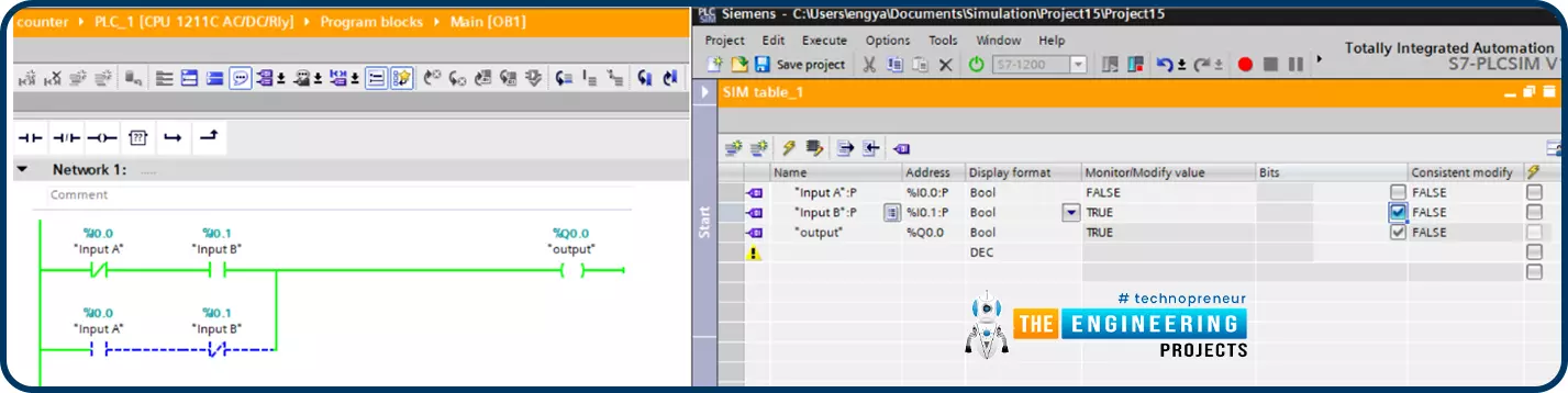
Figure 15, shows the simulation results of XOR when input A is true and input B is true, the output is false.

Simulating advanced logic gate, NAND logic gate, The NANA ladder logic in two ways, NAND ladder logic when both inputs are false, NAND ladder logic when input A is false and input B is true, NAND ladder logic when input A is true and input B is false, NAND ladder logic when both inputs are true, NOR logic gate, XOR logic gate, XNOR logic gate, XNOR ladder logic when input A is true and input B is false, XNOR ladder logic when input A is false and input B is true
Fig 15: The Simulation of XOR ladder when both inputs are true

In a conclusion, the XOR logic in simulation shows that the output is low whenever both inputs are equal and goes high when the inputs are different in the logical state. A very good practical example for utilizing the XOR logic is that imagine friends we have a motor that is energized by two different destinations, and it should be requested by only one at a time. So we can get the run signal from the XOR of the two input switches. So, the only case to run the motor is by requesting from one source.

The “XNOR” Logic Gate

This logic gate is the invert of the XOR gate. So it is equivalent to applying an inverter to the “XOR” logic gate. Table 7 lists the combination of its two inputs and its output. It shows clearly that, the output becomes true when inputs are equal i.e. both inputs are true or both are false.
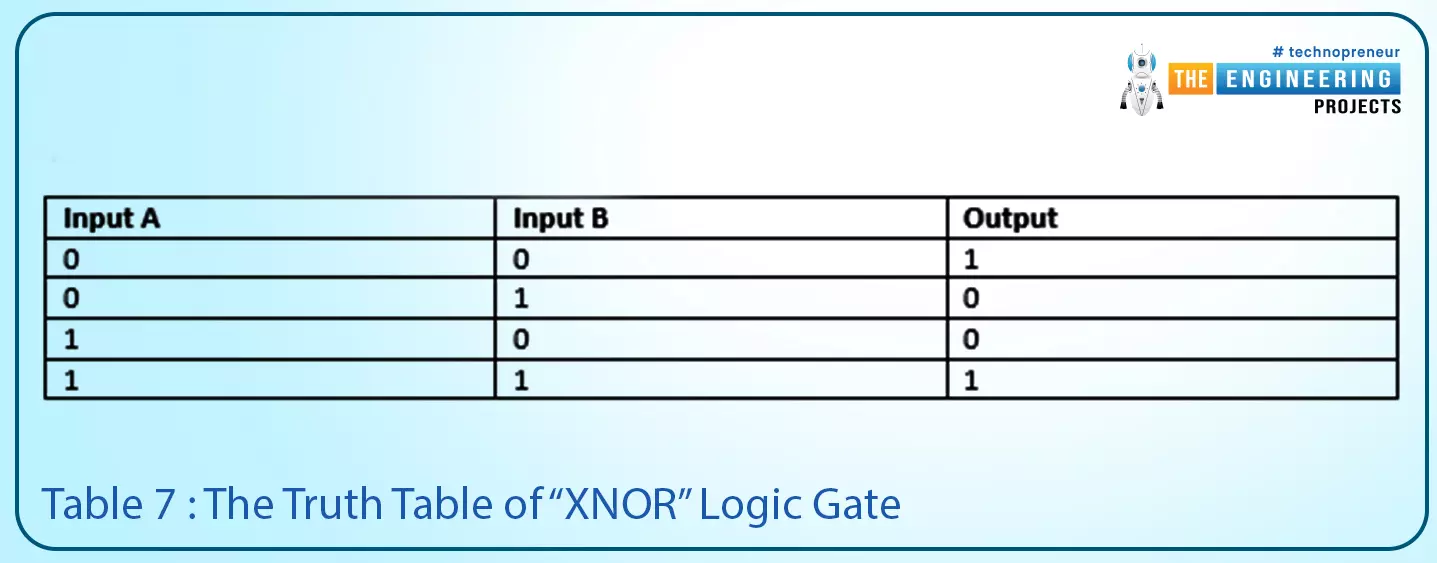
Play with logic gates, Logic gates, Truth table, Basics of logic gate, The AND logic gate, The OR logic gate, The NOT logic gate, NAND logic gate, NOR logic gate, XNOR logic gate, Next logic gate
Table 7: the truth table of the “XNOR” logic gate

Input A Input B Output
0 0 1
0 1 0
1 0 0
1 1 1

Fig. 20 shows the symbol of the “XNOR” logic gate, it shows clearly how it is the invert of the XOR logic gate. This logic gate is very useful to validate if two signals are equal or not.

Play with logic gates, Logic gates, Truth table, Basics of logic gate, The AND logic gate, The OR logic gate, The NOT logic gate, NAND logic gate, NOR logic gate, XNOR logic gate, Next logic gate

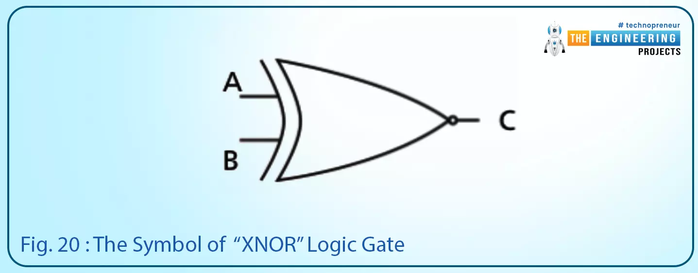
Fig. 20: The symbol of the “XNOR” logic gate

On the other hand, Fig. 21 shows a sample ladder logic of an “XNOR” logic gate implementation. It shows that there are only two ways to have the output in the TRUE state which are by setting both inputs TRUE or set both FALSE.

Play with logic gates, Logic gates, Truth table, Basics of logic gate, The AND logic gate, The OR logic gate, The NOT logic gate, NAND logic gate, NOR logic gate, XNOR logic gate, Next logic gate
Fig. 21: A sample ladder logic for “XNOR” logic

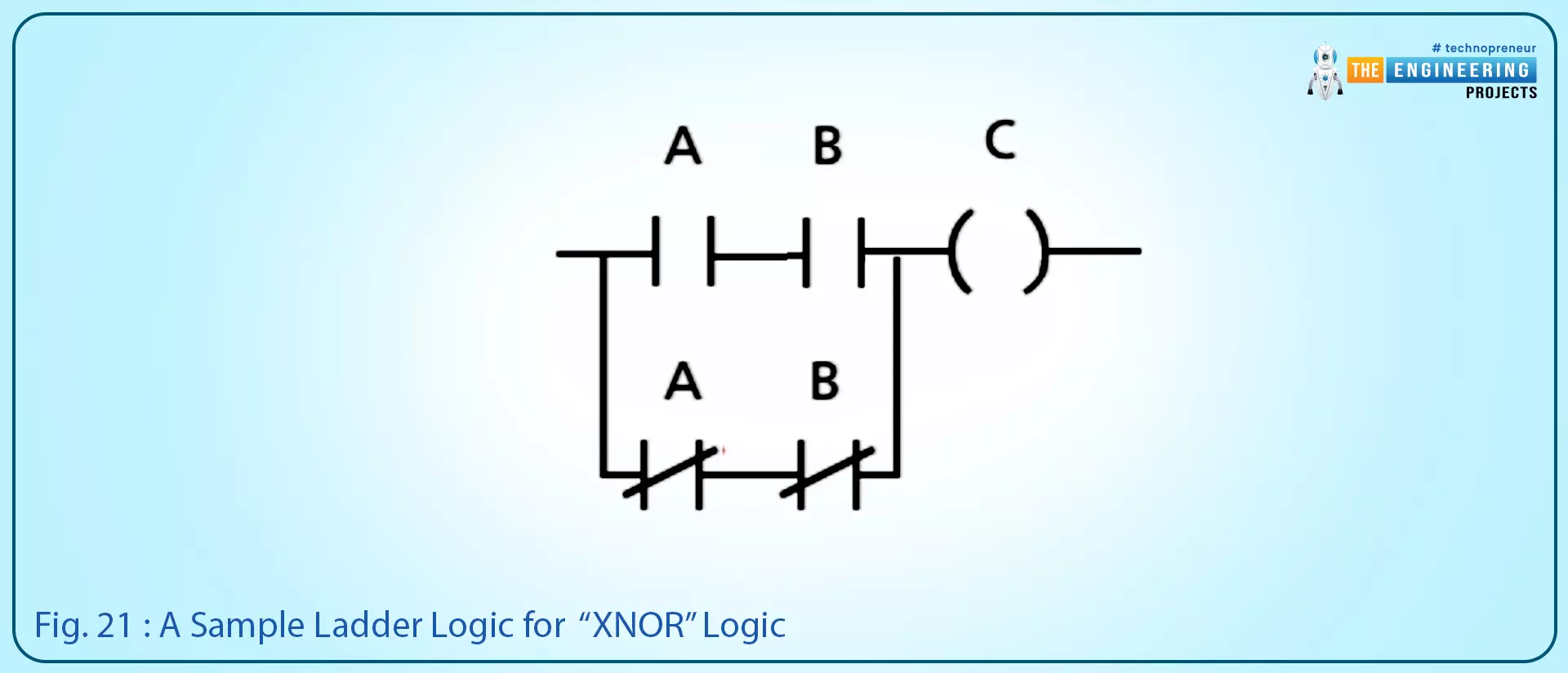
Fig. 22 depicts the timing diagram of the inputs and output of the “XNOR” logic gate and clearly shows the output goes high when both inputs have the same state.

Play with logic gates, Logic gates, Truth table, Basics of logic gate, The AND logic gate, The OR logic gate, The NOT logic gate, NAND logic gate, NOR logic gate, XNOR logic gate, Next logic gate

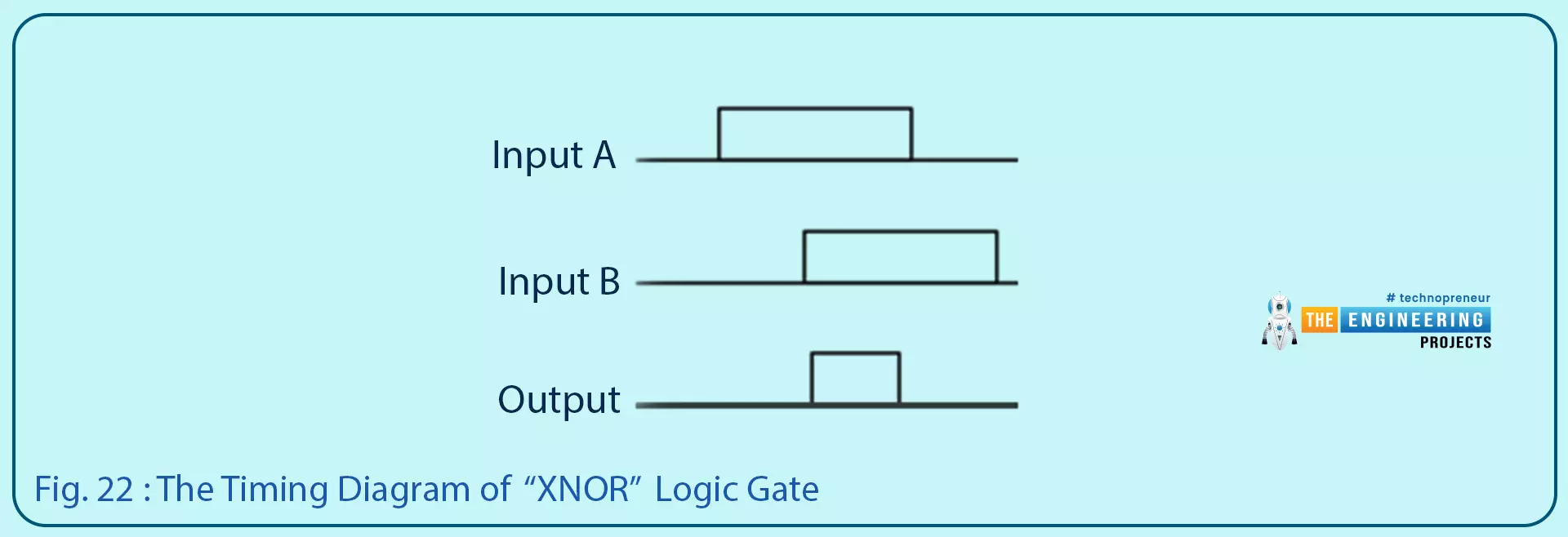
Fig. 22: the timing diagram of the “XNOR” logic gate

XNOR Logic in PLC Simulator

The XNOR is the invert of the XOR and it is used to compare two input signals. Table 4 lists the cases of the truth table of XNOR logic. It shows the output goes high when both inputs are equal i.e. both are high or both of them are low.

Simulating advanced logic gate, NAND logic gate, The NANA ladder logic in two ways, NAND ladder logic when both inputs are false, NAND ladder logic when input A is false and input B is true, NAND ladder logic when input A is true and input B is false, NAND ladder logic when both inputs are true, NOR logic gate, XOR logic gate, XNOR logic gate, XNOR ladder logic when input A is true and input B is false, XNOR ladder logic when input A is false and input B is true
Table 4: the truth table of XNOR logic

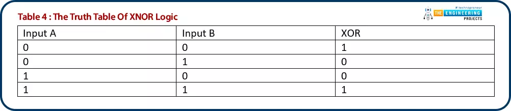
Figure 16 shows the construction of XNOR ladder logic. It shows that it is composed of, two parallel branches and each branch is forming AND logic of the two inputs in the same logical state.

Simulating advanced logic gate, NAND logic gate, The NANA ladder logic in two ways, NAND ladder logic when both inputs are false, NAND ladder logic when input A is false and input B is true, NAND ladder logic when input A is true and input B is false, NAND ladder logic when both inputs are true, NOR logic gate, XOR logic gate, XNOR logic gate, XNOR ladder logic when input A is true and input B is false, XNOR ladder logic when input A is false and input B is true
Fig 16: XNOR ladder logic

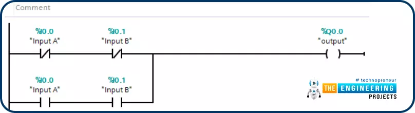
Figure 17, shows the simulation results of XNOR when input A and B are equal i.e. both are false, the output is high.

Simulating advanced logic gate, NAND logic gate, The NANA ladder logic in two ways, NAND ladder logic when both inputs are false, NAND ladder logic when input A is false and input B is true, NAND ladder logic when input A is true and input B is false, NAND ladder logic when both inputs are true, NOR logic gate, XOR logic gate, XNOR logic gate, XNOR ladder logic when input A is true and input B is false, XNOR ladder logic when input A is false and input B is true

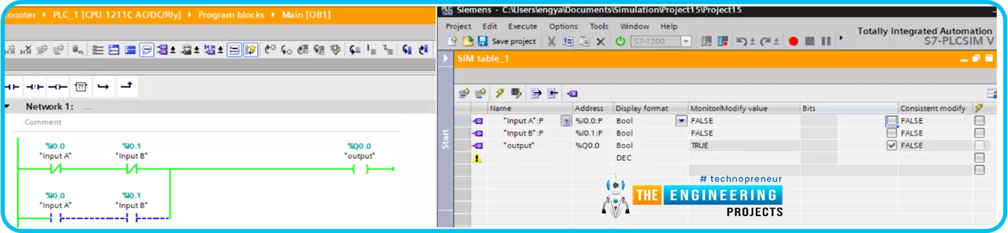
Fig. 17: The Simulation of XNOR ladder when both inputs are false

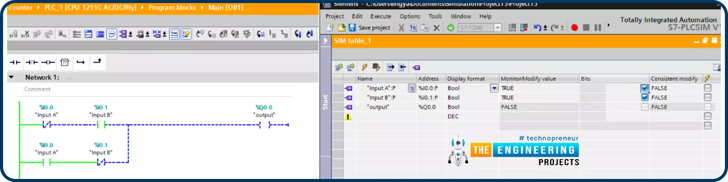
Figure 18, shows the simulation results of XNOR when input A is true and input B is false i.e. they are different. So the output goes false.

Simulating advanced logic gate, NAND logic gate, The NANA ladder logic in two ways, NAND ladder logic when both inputs are false, NAND ladder logic when input A is false and input B is true, NAND ladder logic when input A is true and input B is false, NAND ladder logic when both inputs are true, NOR logic gate, XOR logic gate, XNOR logic gate, XNOR ladder logic when input A is true and input B is false, XNOR ladder logic when input A is false and input B is true

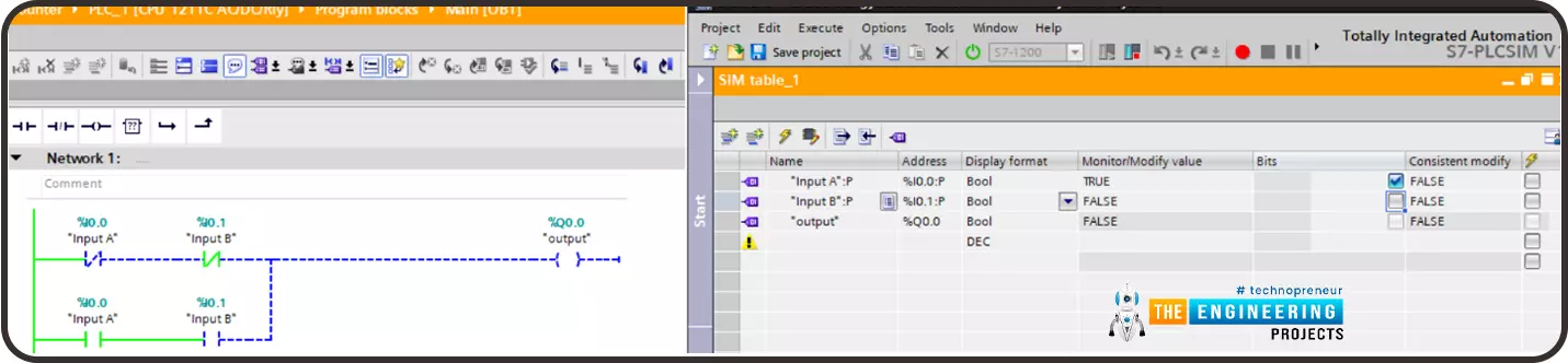
Fig. 18: The Simulation of XNOR ladder when input A is false and input B is high

Figure 19, shows the simulation results of XNOR when input A is false and input B is true i.e. they are different. So the output goes false.

Simulating advanced logic gate, NAND logic gate, The NANA ladder logic in two ways, NAND ladder logic when both inputs are false, NAND ladder logic when input A is false and input B is true, NAND ladder logic when input A is true and input B is false, NAND ladder logic when both inputs are true, NOR logic gate, XOR logic gate, XNOR logic gate, XNOR ladder logic when input A is true and input B is false, XNOR ladder logic when input A is false and input B is true

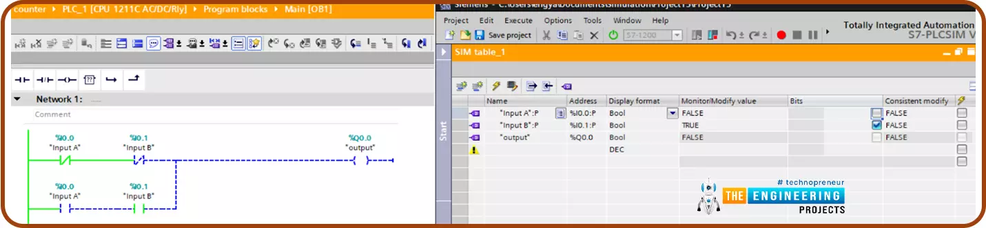
Fig. 19: The Simulation of the XNOR ladder when input B is true and input A is false.

In the last case when both inputs A and B are high as shown in Fig. 20, the output becomes true.

Simulating advanced logic gate, NAND logic gate, The NANA ladder logic in two ways, NAND ladder logic when both inputs are false, NAND ladder logic when input A is false and input B is true, NAND ladder logic when input A is true and input B is false, NAND ladder logic when both inputs are true, NOR logic gate, XOR logic gate, XNOR logic gate, XNOR ladder logic when input A is true and input B is false, XNOR ladder logic when input A is false and input B is true

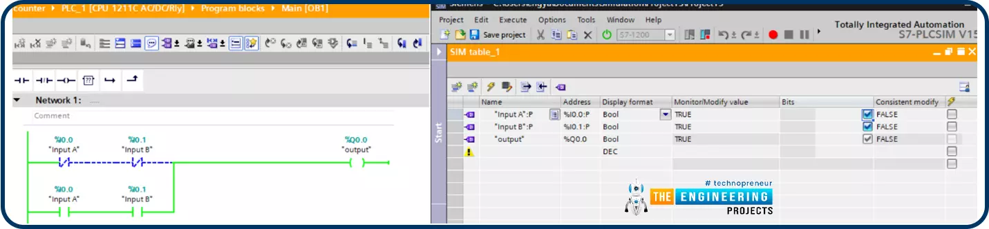
Fig. 20: The Simulation of XNOR ladder when both inputs are true

We can conclude that the XNOR is marked by the true status of its output whenever both inputs are equal and vice versa. One of the most common scenarios for the best practice of XNOR is the protection of the operator's hands in the cutting machine. In that machine, the command for running the knife driving motor is an XNOR of two switches on the left and right hand of the operator. In that way, it is guaranteed that to run the motor, the operator should use both hands at the same time.

What’s next

I am very pleased to see you up to this point of our tutorial, Now you are familiar with all logic gates and practiced their logic on the simulator. In addition, you can feel the importance of mastering all these logic gates to ease your programming and enrich your programming skills. In the next tutorial, we are going to go deeply through the edge signal including rising and falling edge. We are going to introduce the benefits of these edge signals and how they can be utilized in ladder logic programming to solve a lot of problems. So be ready for more learning and practice with simulation in ladder logic series.