Designing Logic Gates in PLC Simulator


We are discussing these logic gates because they are the main building block of complicated logic. Normally, complex logic is designed using multiple logic gates. So, today, we will simulate the basic logic gates i.e. AND, OR, and NOT, while in the next lecture, we will simulate NAND, NOR, XOR and XNOR in PLC Simulator. So, let's get started:
Logic gates
In very simple language, it is a Boolean decision that has one of only two values either “TRUE” or “FALSE”, not both. For instance, the decision to run or shut down a motor, open or close a valve etc. Well! For deciding such Boolean nature thing, there are two things, inputs and logic to apply on those inputs. On the other way, logic gates apply some sort of logic to the inputs to determine the state of the output.
Truth table
It’s a table that lists all possible combinations of the inputs and the state of the output for each record. For example, a gate with two inputs has four possible combinations of the inputs and four states of the output. inputs.
Basics of logic gate
There are seven basic logic gates. Some of them have only one input while others have two inputs. There are seven basic logic gates which are “AND”, “OR”, “NOT”, “NOR”, “XOR”, “XNOR”, and “NAND”. So let us enjoy a short journey with them having a fast stop at each one’s station. Our trip will include, how they work, design, timing diagram, and connection with ladder logic programming.
Simulating ANR, OR, and NOT logic
- The AND, OR, and NOT logic are considered the basic building block logic for designing the complicated logic to decide the output status.
- By using two switches A and B and one output representing lamp or MOTOR, we can design and program these logics and simulate them on the PLCSIM simulator.
- Table 1 lists the truth table of the three logic AND, OR, and NOT.
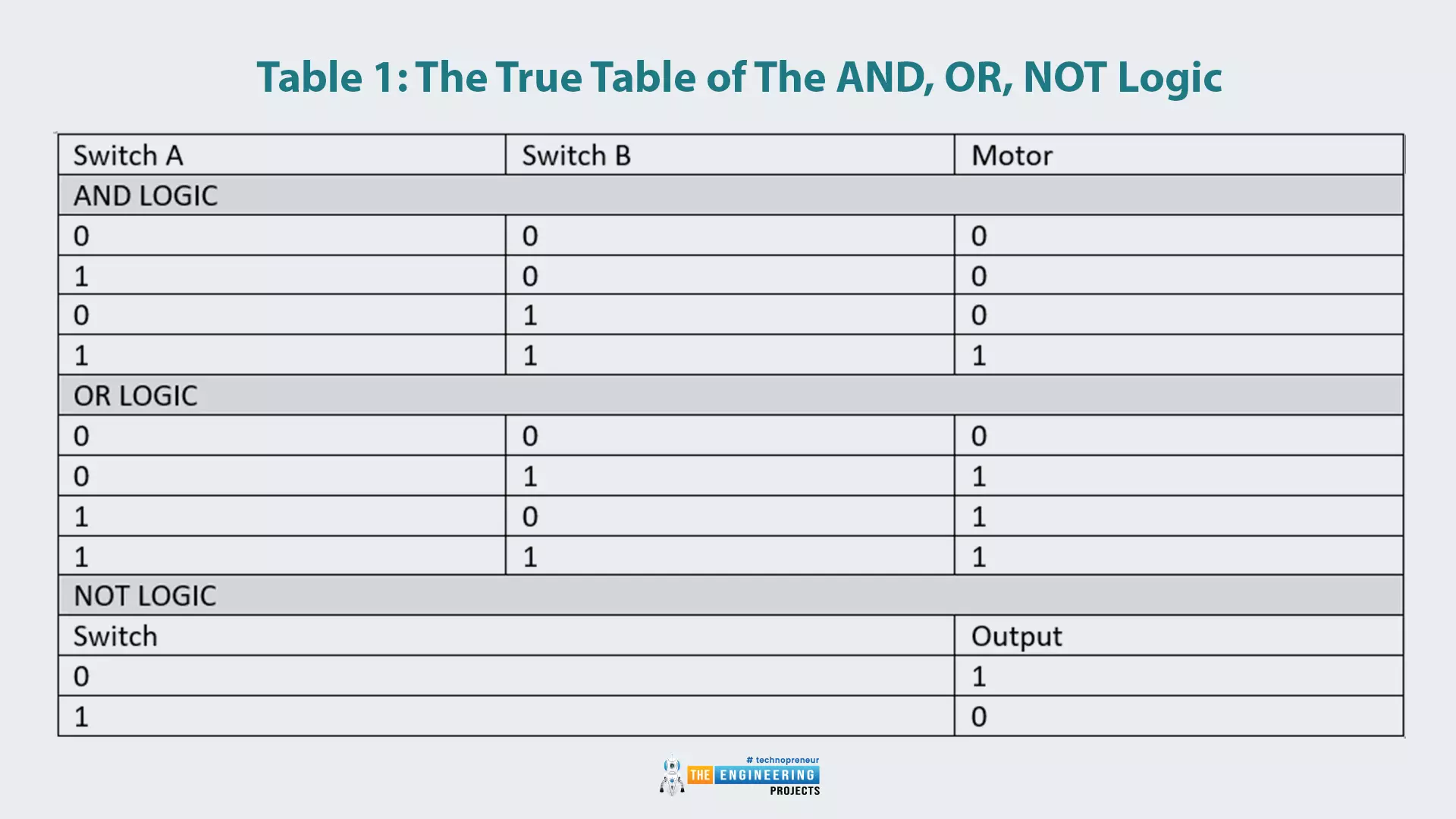
Table 1: Truth table of the AND, OR, NOT logic
| Switch A | Switch B | Motor |
| AND LOGIC | ||
| 0 | 0 | 0 |
| 1 | 0 | 0 |
| 0 | 1 | 0 |
| 1 | 1 | 1 |
| OR LOGIC | ||
| 0 | 0 | 0 |
| 0 | 1 | 1 |
| 1 | 0 | 1 |
| 1 | 1 | 1 |
| NOT LOGIC | ||
| Switch | Output | |
| 0 | 1 | |
| 1 | 0 | |
The “AND” Logic Gate
The “AND” logic gate has two inputs and one output. Like its name, the only condition for having the output become true, is by having both inputs, input A and input B are true. Table 1 lists the truth table of the “AND” gate and Fig. 1 images the symbol of the “AND” gate. In addition, Fig. 2 shows a sample of ladder logic rung that uses “AND” gate logic. It decides the status of the motor based on two switches. The two switches must be in true status for running the motor. ‘to sum up, the logic of the “AND” gate, is that, the output comes to true when and only when both inputs A and B are true.
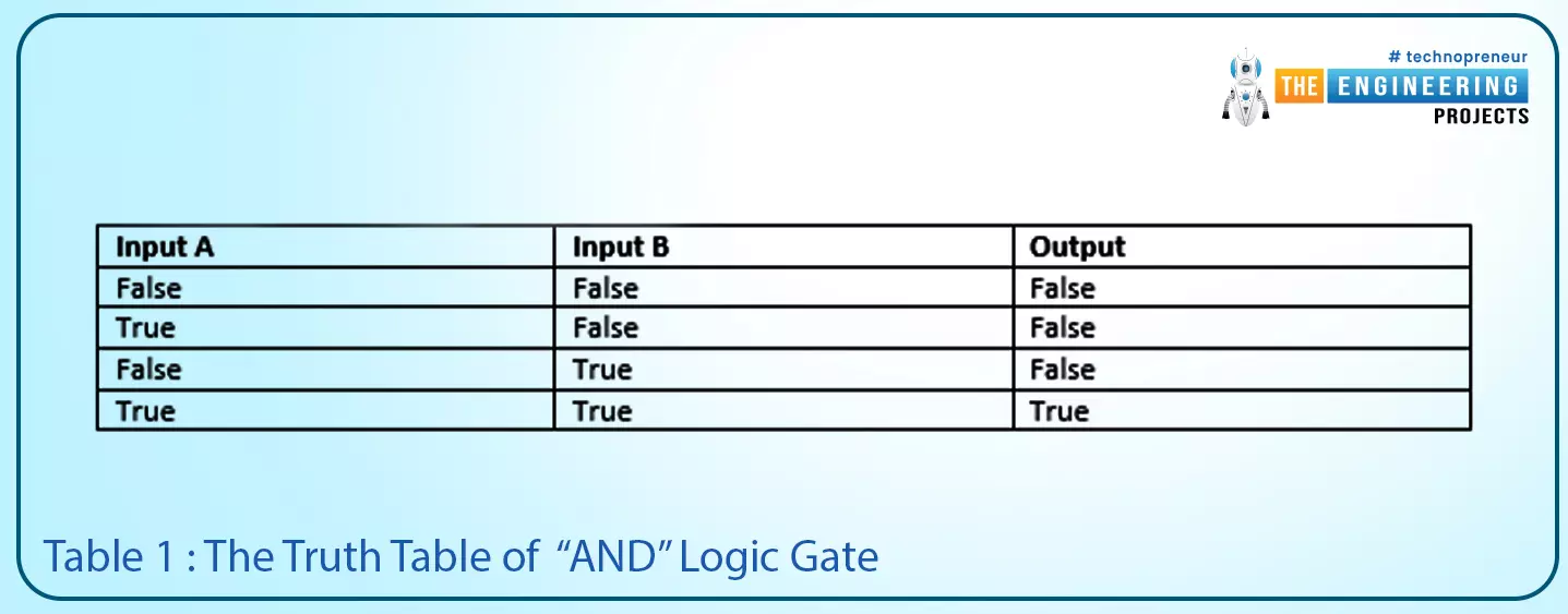
| Input A | Input B | Output |
| False | False | False |
| True | False | False |
| False | True | False |
| True | True | True |
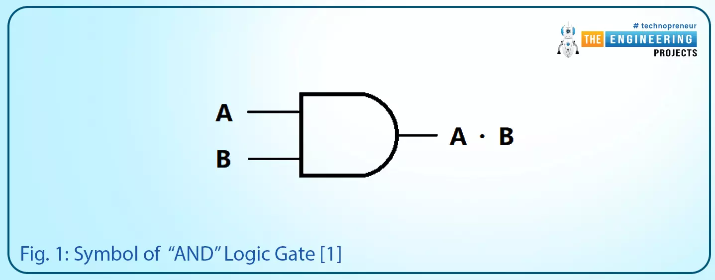
Fig. 1: symbol of “AND” logic gate [1]
In the ladder logic rung shown in Fig. 2, there are two contacts I1 and I2, they are of normally open (NO) type, these two contacts are connected in series, so the only way to set the output to true is that both contacts I1 and I2 must set to true. For full imagination, please notice the timing diagram of the inputs and output signals shown in Fig. 3. It shows the output is only high when both inputs are high.
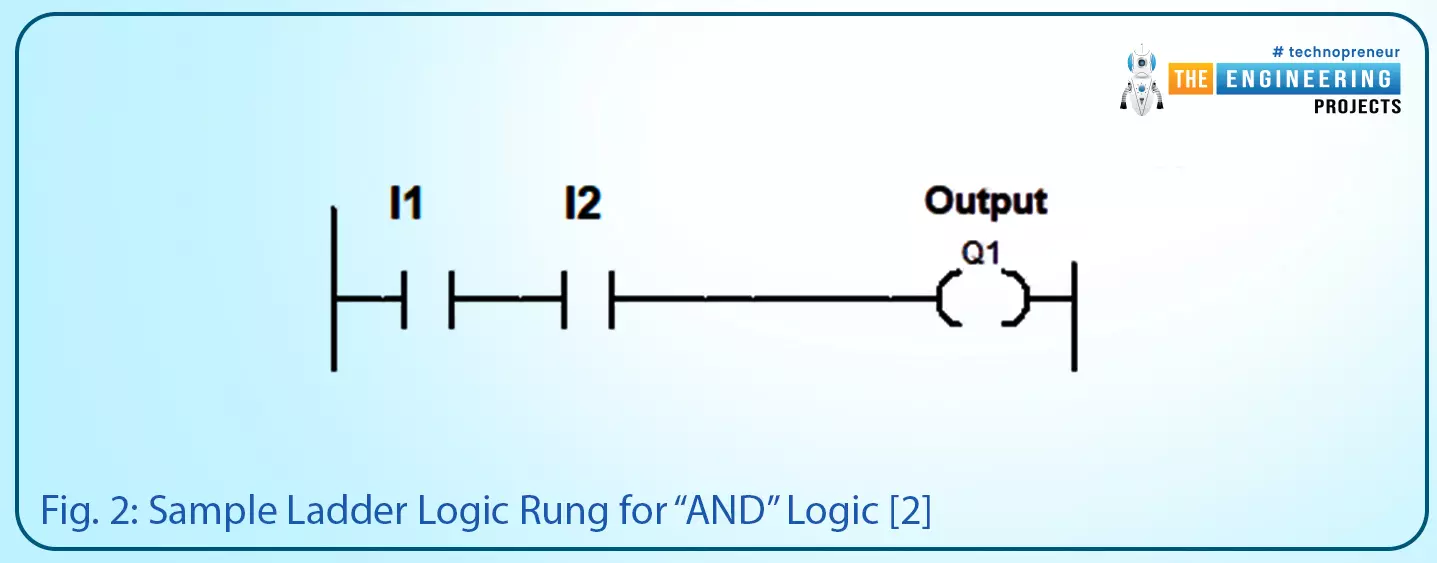
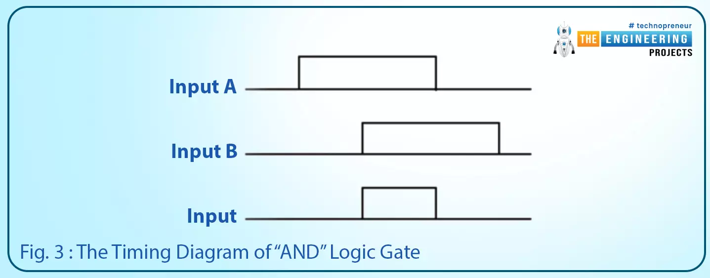
Fig. 3: The timing diagram of the “AND” logic gate
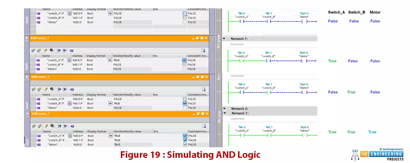
AND logic in PLC simulator
- Let us once more enjoy learning further by validating and practicing on the simulator, here you can see in figure 19, on the right the AND logic has been programmed by connecting two switches A and B in series.
- The motor status is the result of the AND logic between the two switches.
- On the left, you can see the results of the simulation by setting the status of switches to simulate all truth table conditions and see the motor status changed accordingly.
- In addition, you can see the truth table of the AND logic on the most right of the figure. So you can review and validate what is going on in the simulator.
Figure 19: Simulating AND logic
The “OR” Logic Gate
This logic gate has two inputs and one output like the “AND” gate. Like its name, the output comes true when either input A or input B comes true as shown in Fig. 4.
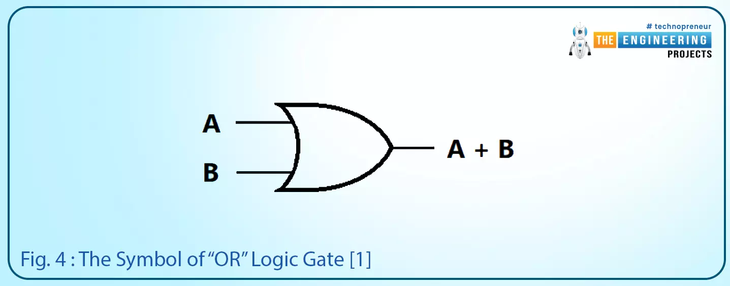
Fig. 4: The symbol of “OR” logic gate [1]
Table 2 lists the truth table of the “OR” gate. It lists all possible combinations of inputs and the output status as well. It shows that the output comes to true when input A or input B comes to true.
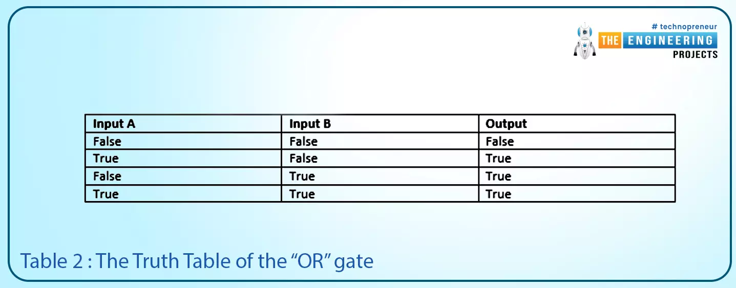
| Input A | Input B | Output |
| False | False | False |
| True | False | True |
| False | True | True |
| True | True | True |
Figure 5 shows an example of a ladder logic rung that implements the “OR” logic. We can implement this by connecting two inputs I1 and I2 in parallel branches and to the output. like this way of connection, the output can be set to true by simply setting I1 or I2 or both true. Once more, let us see the timing diagram in fig. 6, it is clearly shown that the output goes high as long as either one or both of the inputs are true.
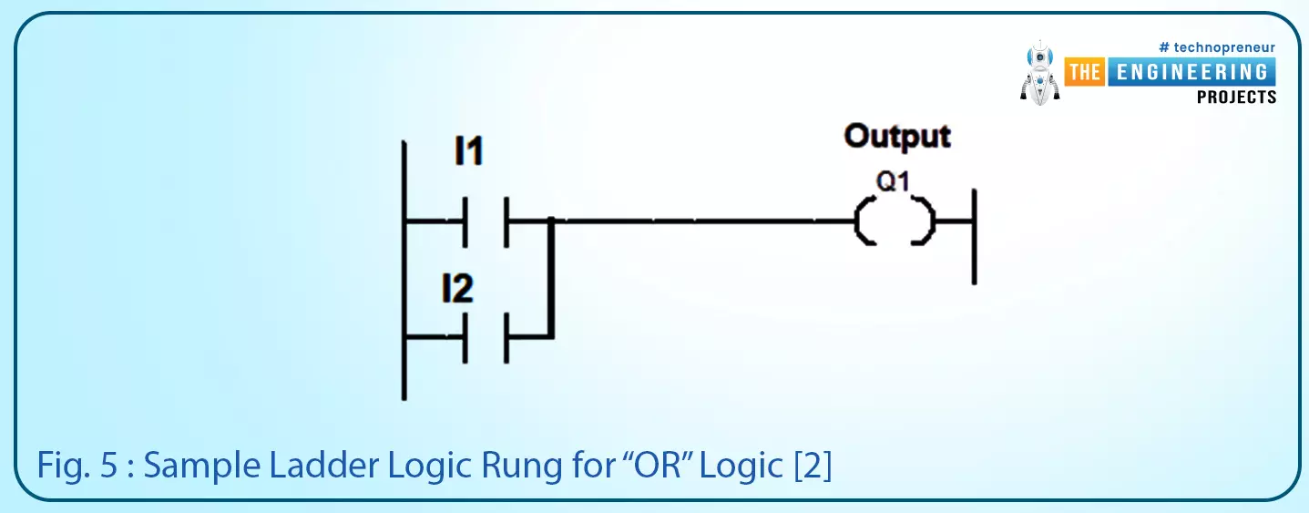
Fig. 5: sample ladder logic rung for “OR” logic [2]
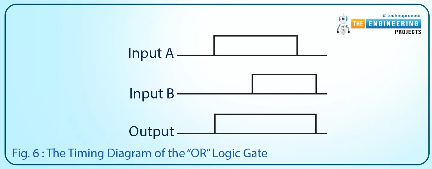
Fig. 6: the timing diagram of the “OR” logic gate
OR logic in PLC Simulator
- You can see in figure 20, on the right the OR logic has been established and programmed by connecting two switches A and B in parallel.
- The motor status is the result of the OR logic between the two switches.
- On the left, you can see the results of the simulation by setting the status of switches to simulate all truth table conditions of the OR logic and see the motor status charged accordingly.
- In addition, you can see the truth table on the most right of the figure. So you can review and validate what is going on in the simulator.
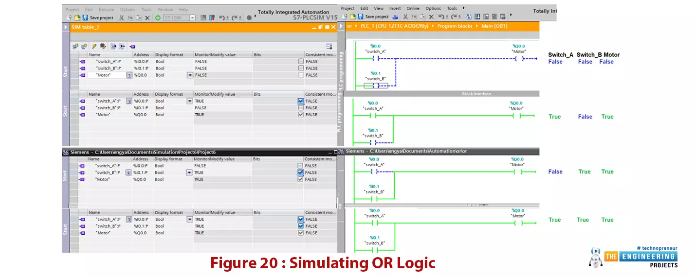
Figure 20: Simulating OR logic
The “NOT” logic gate
This logic gate has only one input and one output. In a very simple language, the output is the invert logic of the input. So when the input is true, the output would come to false and vise versa as shown in Fig. 7.

Table 3 lists the truth table rows of all possible combination of input and output.
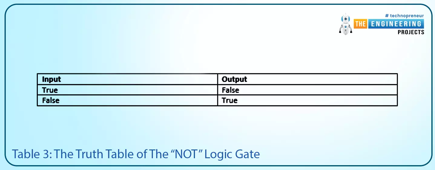
Table 3: the truth table of the “NOT” logic gate
| Input | Output |
| True | False |
| False | True |
Figure 8 depicts a very simple example of a ladder logic rung that shows the output Q1 is the reverse logic of the input I1. In addition, Fig. 9 shows the timing diagram of input and output of the “NOT” logic gate. It shows clearly that, the output is the reverse of the input.
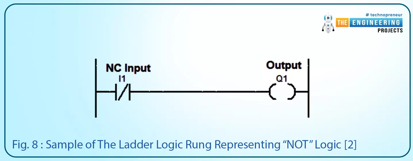
Fig. 8: Sample of the ladder logic rung representing “NOT” logic [2]
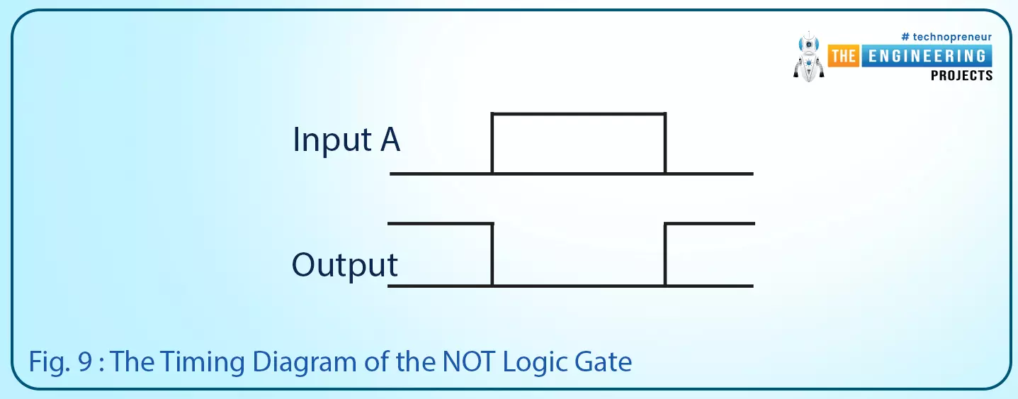
Fig. 9: The timing diagram of the NOT logic gate
Before going further with the logic gates, I want to let you know the good news that, you can implement any logic by using the aforementioned three logic gates “AND”, “OR”, and “NOT”. However, for simplification, the other logic gates are designed based on using these three logic gates in different topologies to perform a specific logic functions.
Not logic in PLC Simulator
- Also, the NOT logic is one of the primary logic functions, you can see in figure 21, on the right the NOT logic has been designed and programmed by connecting switches A in negative logic in series with the motor.
- The motor status is the result of the NOT logic of switch A. On the left, you can see the results of the simulation by setting the status of the switch to simulate the two-state of the NOT logic truth table and see the motor status charged accordingly.
- In addition, you can see the truth table on the most right of the figure. So you can review and validate what is going on in the simulator.
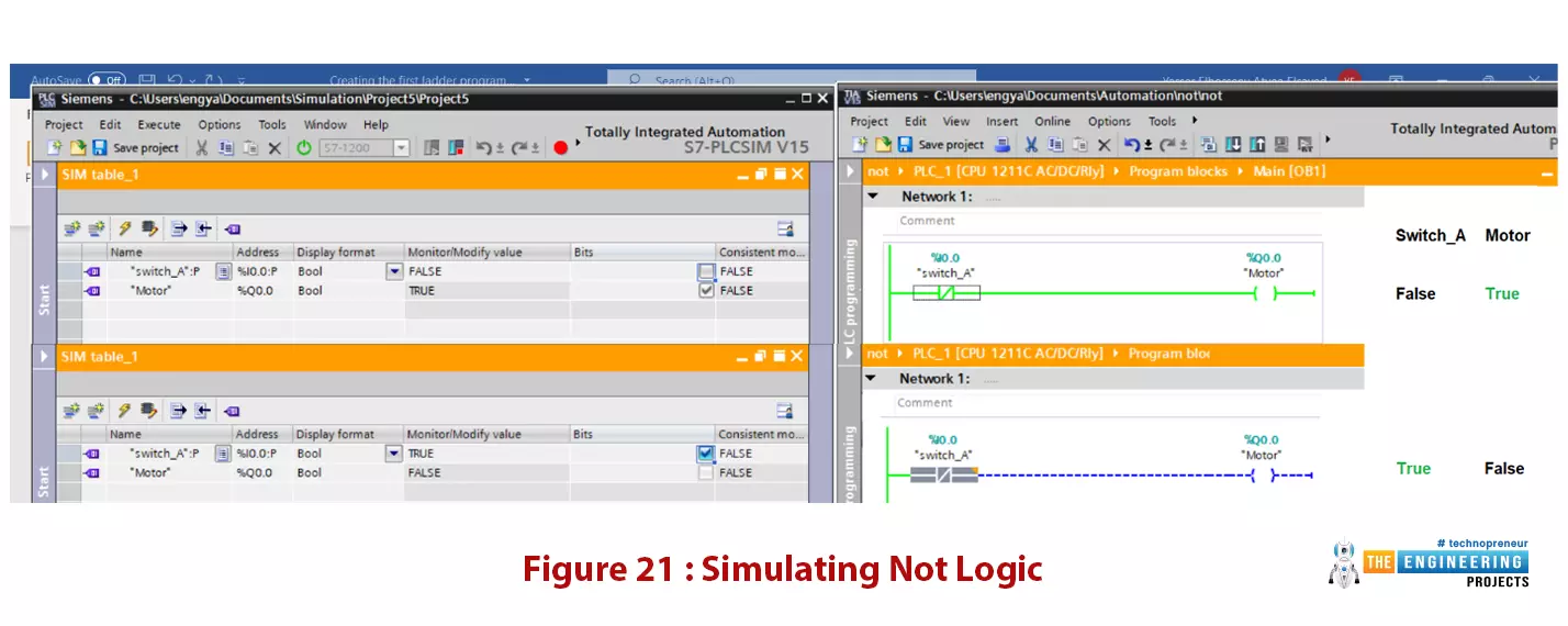
Figure 21: simulating Not logic
Now! I appreciate your follow-up to our PLC tutorial. I am very happy to feel that, by moving further in our plc tutorial our experience is getting increasing bit by bit. However, some questions may come to our mind like does the operator needs to keep pressing input like the push button to keep the motor running? What happens if he released it, does the motor stop? Well! By asking such questions, I can affirm you start your way to master PLC programming and its logic. And let me say the answer to your questions is yes the operator needs to keep pressing the input push-button until the motor has done its task. But that is not the best practice in the real life. There are other techniques to keep the motor running by one touch of the push button, thanks to latching, setting, and resetting techniques as we will show you in the next sections.
Latching output
- Figure 22 depicts the latching technique that we simply use to keep the motor running by pressing the input push button and having it keep running even after releasing the button.
- As you can see, I have used the Output as a Virtual Input and placed it in parallel with actual input.
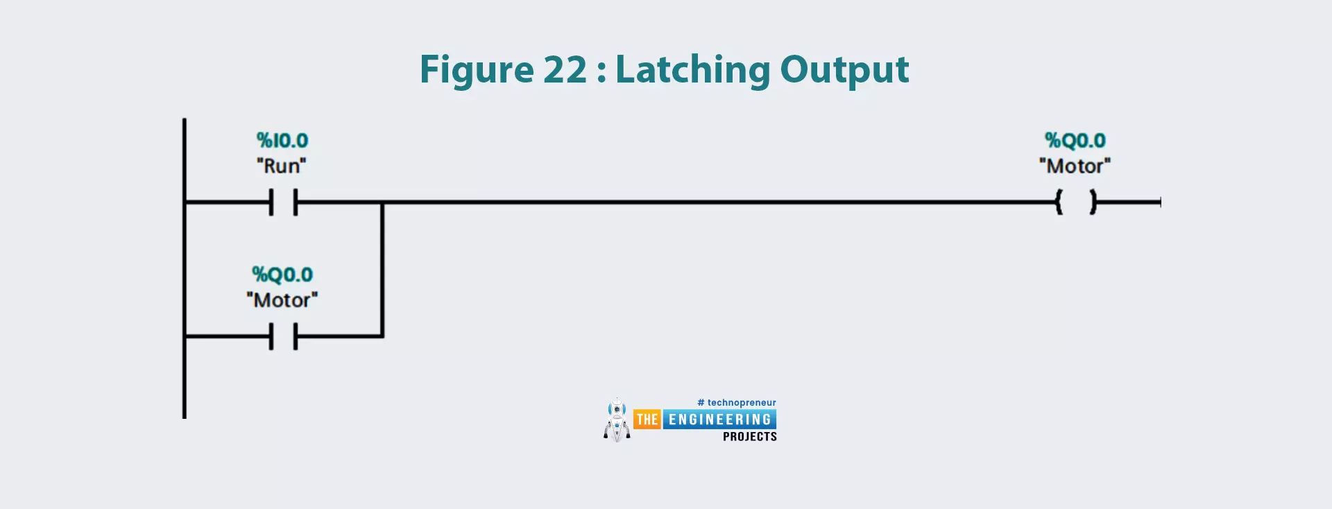
- Table 2 lists the First three scan cycles to show the sequence of operations and how the latching process works when someone will press the Input.
- In the first scan cycle, when the input gets HIGH, the plc will scan the input "Run (I0.0)" and will find it pressed/ON and thus will make the output "Motor (Q0.0)" HIGH.
- In the second scan cycle, the input "Run (I0.0)" turned off after being released, but the motor contact is still ON from the previous scan cycle.
- So, the compiler won't change the status of the OUTPUT and we can say it's latching the output.
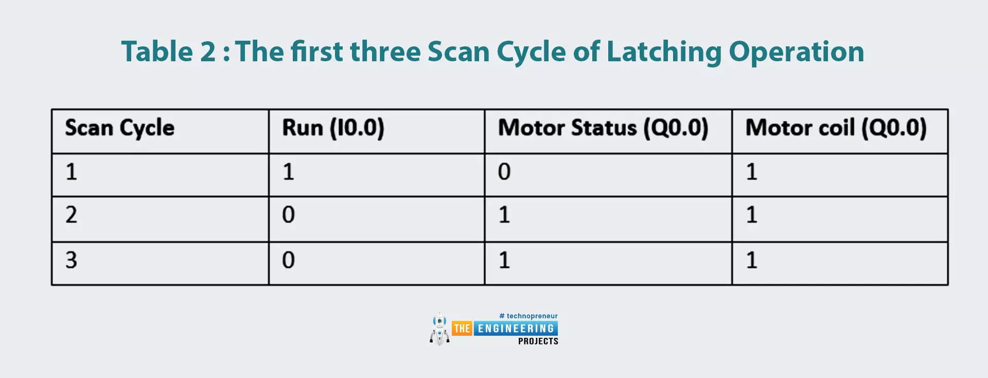
Table 2: The first three scan cycles of latching operation
| Scan cycle | Run (I0.0) | Motor status (Q0.0) | Motor coil (Q0.0) |
| 1 | 1 | 0 | 1 |
| 2 | 0 | 1 | 1 |
| 3 | 0 | 1 | 1 |
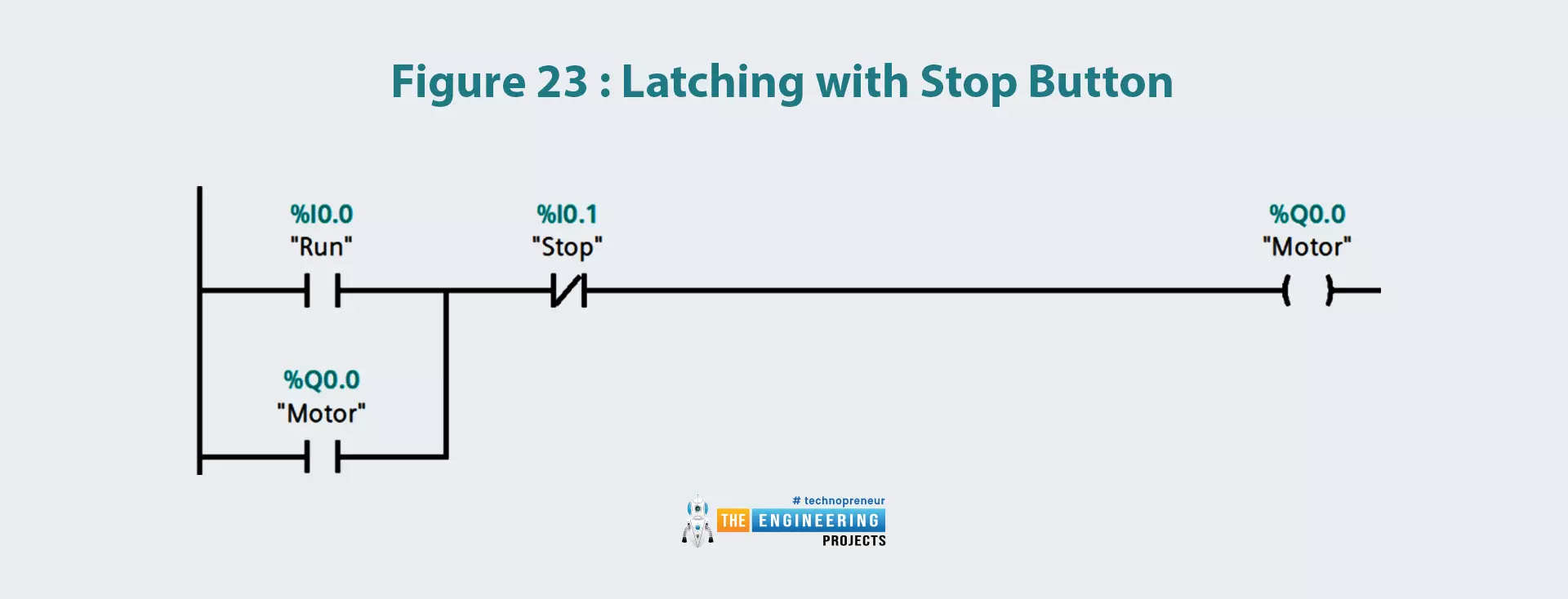
- Now let’s add a way to terminate the latching and stop the motor as per request.
- Well! Simply figure 23 shows a stop button is added for terminating the latching condition.
- So in table 2, the RLO for letting the motor running will be unfulfilled by hitting the stop push button in the third scan cycle.
Simulation of the latching in ladder logic
We may be sure of the logic we wrote for coding the ladder logic of the latching technique. However, at this point how about going to the simulation lab to work out our latch ladder logic program to enjoy validating our ladder code by putting it in the simulator and see how far it match what it is designed for.
Latching Ladder code simulation
- Now let’s try our latching ladder program in the PLCSIM simulator, by entering our ladder logic and starting the simulator.
- Figure 24 shows the first four scan cycles. Notice on the left we can set the inputs on and off and see the effects on the right part.
- In the first scan, every single input and output is at its initial state, so the output is not energized.
- In the next scan cycle, you can notice we switch on input at I0.0 which is the start push button.
- Therefore, the motor has been started and running. In the third scan cycle, the start button is switched back off.
- However, the motor still runs thanks to the latching technique. WOW, we can see our logic is working as we designed for.
- In the last scan cycle, we tried to test stop latching by hitting the stop pushbutton and indeed it stopped latching and the motor stop running.
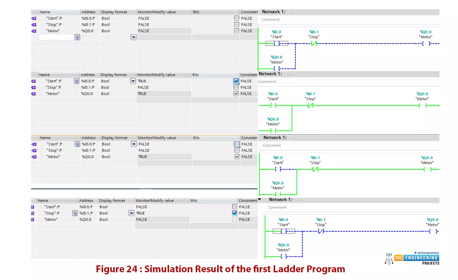
Figure 24: simulation result of the first ladder program
We will concentrate on moving forward with ladder coding which is our target. However, we just tried to show you at any time you can validate your ladder at any point to enjoy and confirm you are on the right track as long as you are working on your project.
Latching using set and reset
Let’s use another approach for latching which is based on using set and reset coil. Figure 25 shows the set and reset methods.
- By hitting set_valve at address I0.2, the valve at Q0.0 will be set ON until a reset command is present by hitting the reset_valve pushbutton at I0.3.
- It is very easy but you need to take extra care while using set and reset as the last set/reset command will overwrite the previous commands.
- But wait, what’s if an operator keeps pressing the rest or set button for a long time or if the pushbuttons are the stuck and same thing for the stop button.
Well! The rational expectation is that the motor won’t be able to start. However, the good thing is there is a magic solution to differentiate between the situation of this is a normal stop request by the operator or the button is hold pressed unintentionally or due to an issue with the switches. The one-shot technique can magically recognize the event of pressing or releasing the pushbuttons. Therefore, when it is held for a long time or forever that is only one button press event and for triggering it needs to release and pressed once again. That’s amazing but how does it work? Well! Let’s go demonstrate the concept of how it works, implementation using ladder logic, and give an example to understand it consistently and enjoy the magic of one-shot action.
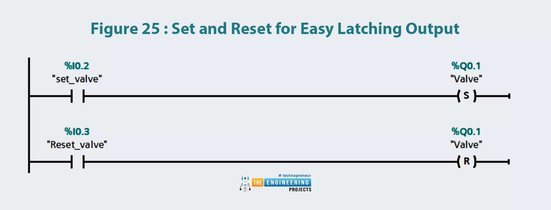
Figure 25: set and reset for easy latching output
The signal edges
Two edges happened when a pushbutton pressed and released which are falling edge and rising edge as shown in figure 26. It depicts the rising edge when the button is pressed and the falling edge when it has been released. Now, let's move to ladder logic, there are two equivalent rising and falling edge contacts that can be used to tell the PLC this is a one-shot signal. Figure 27 shows how the use of the rising edge of the reset pushbutton |P| at address I0.3. it shows that despite the reset being pressed, its effect in the moment of pressing and then it needs to be released and pressed again to reset the valve at Q0.1. in the next section, let’s get to business and work out one practical example which represents a real problem in the industry just to harvest the fruit of what we have learned so far.
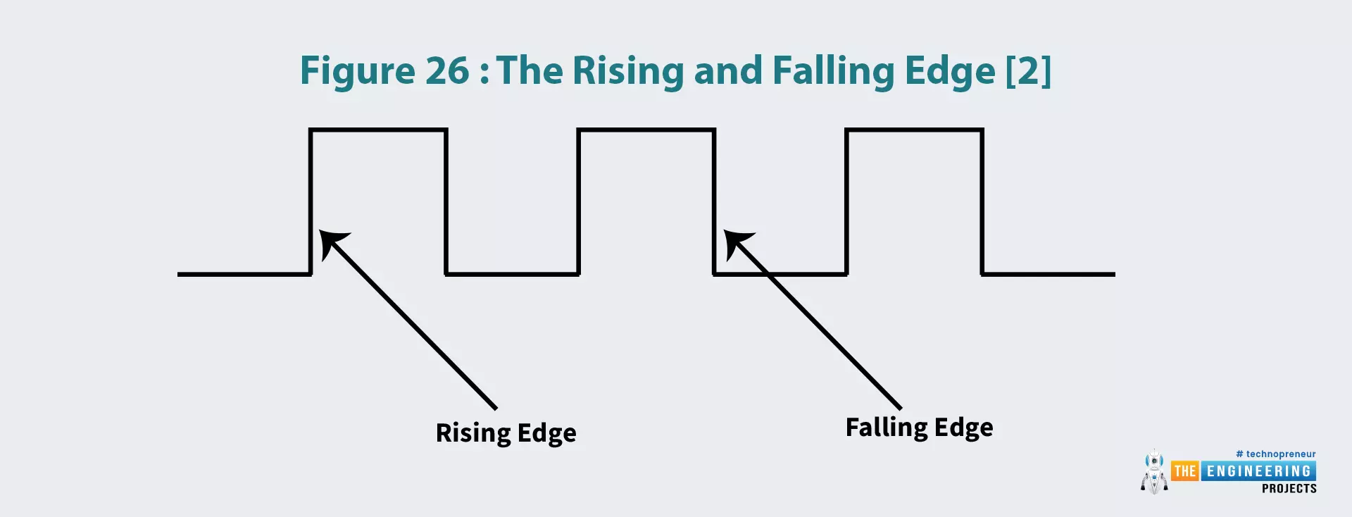
Figure 26: The rising and falling edge [2]
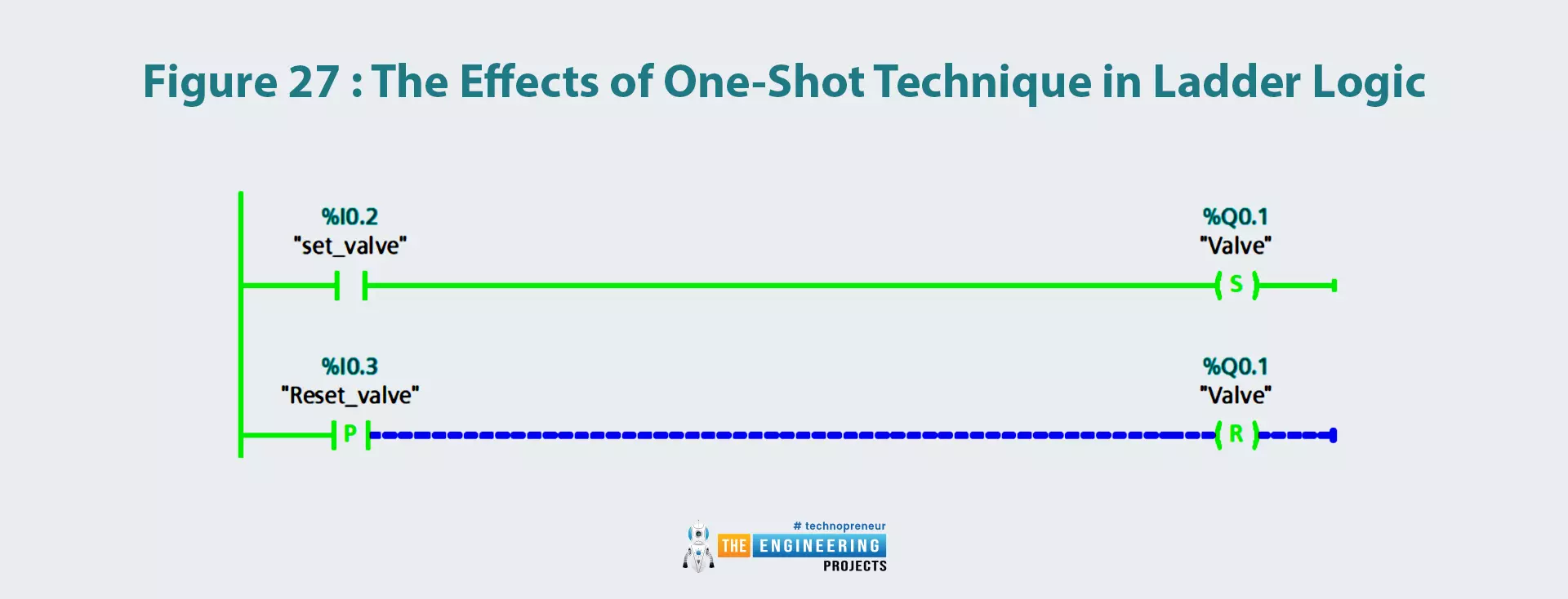
Figure 27: The effects of one-shot technique in ladder logic
So, that was all for today. I hope you have enjoyed today's lecture. In the next tutorial, we will simulate Advance Logic Gates using Ladder Logic Programming. We will design NAND, NOR, XOR and XNOR gates in the next lecture. Thanks for reading.