Design an Automatic Door with Ladder Logic Programming


Hi Guys! hope you are doing great today! We come this time with a complete project to work out together starting from the point at which we sit with the client and receive the logical narratives that represent what they want to implement. We are going to start with a simple project this time and continue increasing the scale and complexity of the requirements through the incoming tutorials. The project we are going to implement today is one of the most common tasks that we can find in every place in our real life which is the control of the garage door. That could be found in private property or commercial buildings or public garages. Too many things need to be controlled in garage doors and several scenarios could come to your mind. However, take it as a rule of thumb that we design our program based on the requirements specified by the customer not based on our thoughts.
Project Introduction
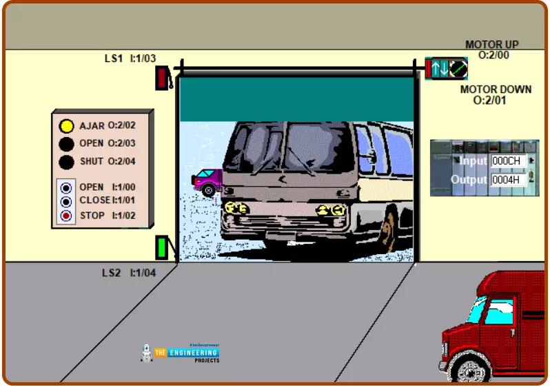
Figure 1 images the project with details. As you can see, it is a garage door that is required to be controlled to open, and shut down flexibly and safely. Flexible operation means it needs to open and shut down at any time exchangeable showing operation indicators when it is opening and when it is closing. And safe operation means taking care of the motor and system components when the change between open and shut down commands for not make any kind of hazard to the system components.

Control Logic Philosophy
The control logic philosophy is a common term you will be used to hear when you meet with the clients who are going to discuss with you the control logic and all scenarios which will be interpreted by you to the control narratives. The following control narratives of the project were decided and designed based on the discussion with the customer who requested the control system and it is as follows:
There will be a control panel with a front panel that has push buttons, indicator lamps, and switches that enable the end user of operating the system including all functions of the control system. that includes one push button for commanding the door to open and one other push-button for instructing the system to shut down the door. In addition, one indicator to show the door is opening, one to show the door is closing, and one to show the door is in ajar status or open slightly.
The system needs to have a safety emergency stop switch to stop the operation at any instant
The system also can switch between opening and shutting down at any time when it is allowed to do
The system needs to be safe and secure from any hazards that might occur due to wrong logic design for example requesting one operation which might cause any damage to the system components like motors
Please note that when the customer lists the requirements he or she does not know about the deep technical details like the system components that the system needs including push buttons, indicating lamps, switches, sensors, and actuators because he or she is supposed to talk at a high level while telling you the requirements and you the one who should translate his requirements into logic narratives and deciding for the whole system components.
Logic narratives and system components
Guys! now our work has just started by translating the above high-level requirements into detailed logic narratives and also deciding all system components and input-output lists. Figure 2 shows the garage door project with the system components that include actuators, sensors, switches, push buttons and indicator lamps.
System components
Table 1 lists the system components which include the main motor running up and down for opening and shutting down. Limit switches for preventing the door from opening and shutting down. Also, it includes the indicators and operation status while opening and closing and ajar status as well. Also, one emergency stop is utilized to stop the process at any time. The table includes the component name, description, the related IO type, and address. For example, the main motor of the door can be run in two directions to let it open or shut down. Therefore, two coils are connected through two digital outputs at addresses O:02/0 and O:02/01 which are the third output input card and the first and second channels. Also, two limit switches have been utilized to control the limits up and down to which the door can go. They are connected to two digital inputs at addresses I:01/03 and I:01/04 which are connected to the second digital input card at the 4th and 5th channels. In addition, two push buttons to handle the open and shutdown requests of the door have been connected at addresses I:01/00 and I:01/01 which are the first and second channels of the second digital input card. And the E-stop or the emergency stop has been connected to digital input at address I:01/03 which is the 4th channel of the second digital input card. Last but not least, three lamp indicators are connected via three digital outputs which are connected to addresses O:02/02, O:02/03, and O:02/04 which are the third digital output card in the rack and the third, fourth, and fifth channels respectively.
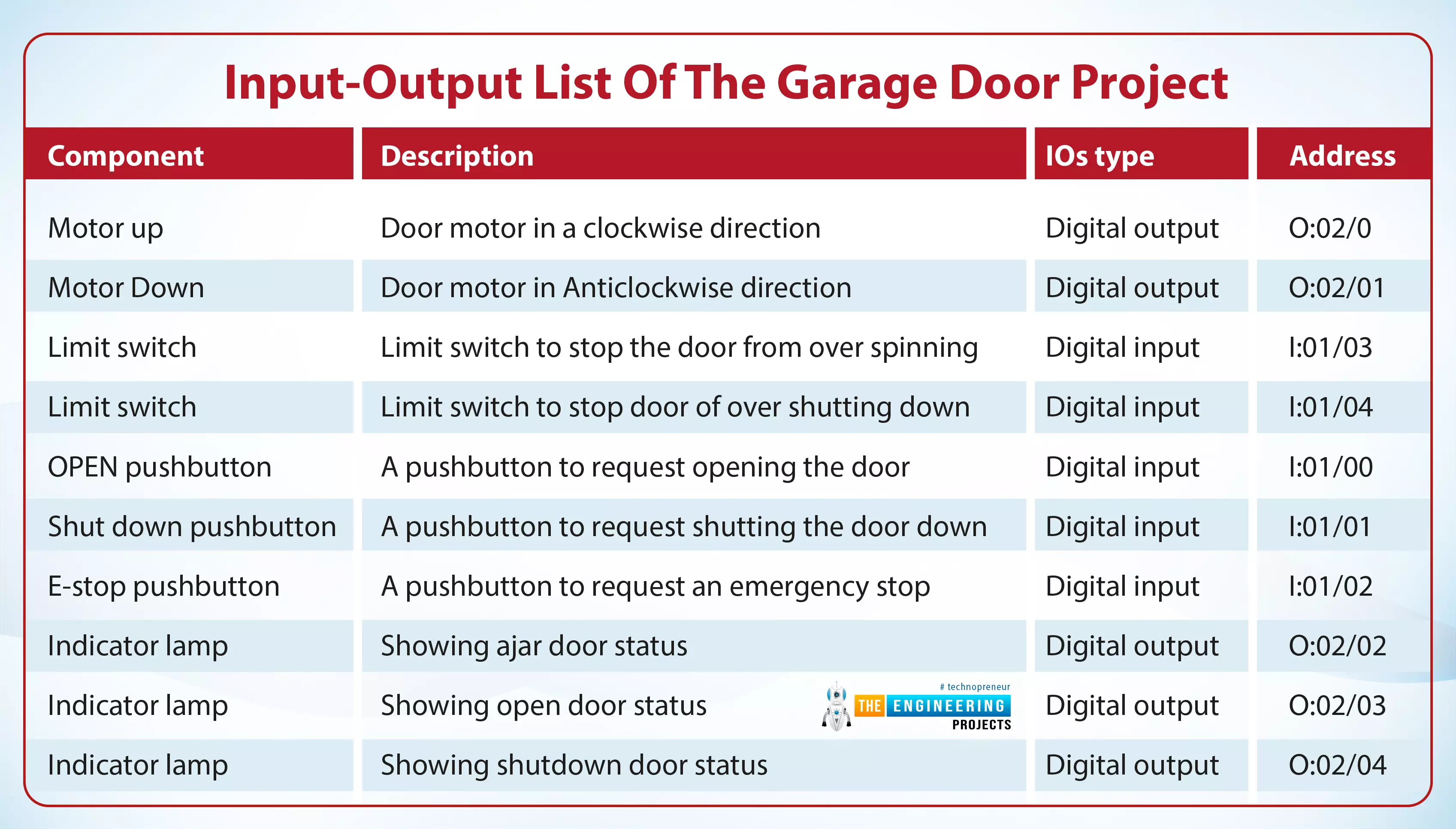
Table 1: Input-output list of the garage door project
Component |
description |
IOs type |
Address |
Motor up |
Door motor in a clockwise direction |
Digital output |
O:02/0 |
Motor Down |
Door motor in Anticlockwise direction |
Digital output |
O:02/01 |
Limit switch |
Limit switch to stop the door from over spinning |
Digital input |
I:01/03 |
Limit switch |
Limit switch to stop door of over shutting down |
Digital input |
I:01/04 |
OPEN pushbutton |
A pushbutton to request opening the door |
Digital input |
I:01/00 |
Shut down pushbutton |
A pushbutton to request shutting the door down |
Digital input |
I:01/01 |
E-stop pushbutton |
A pushbutton to request an emergency stop |
Digital input |
I:01/02 |
Indicator lamp |
Showing ajar door status |
Digital output |
O:02/02 |
Indicator lamp |
Showing open door status |
Digital output |
O:02/03 |
Indicator lamp |
Showing shutdown door status |
Digital output |
O:02/04 |
Project Logic Flow
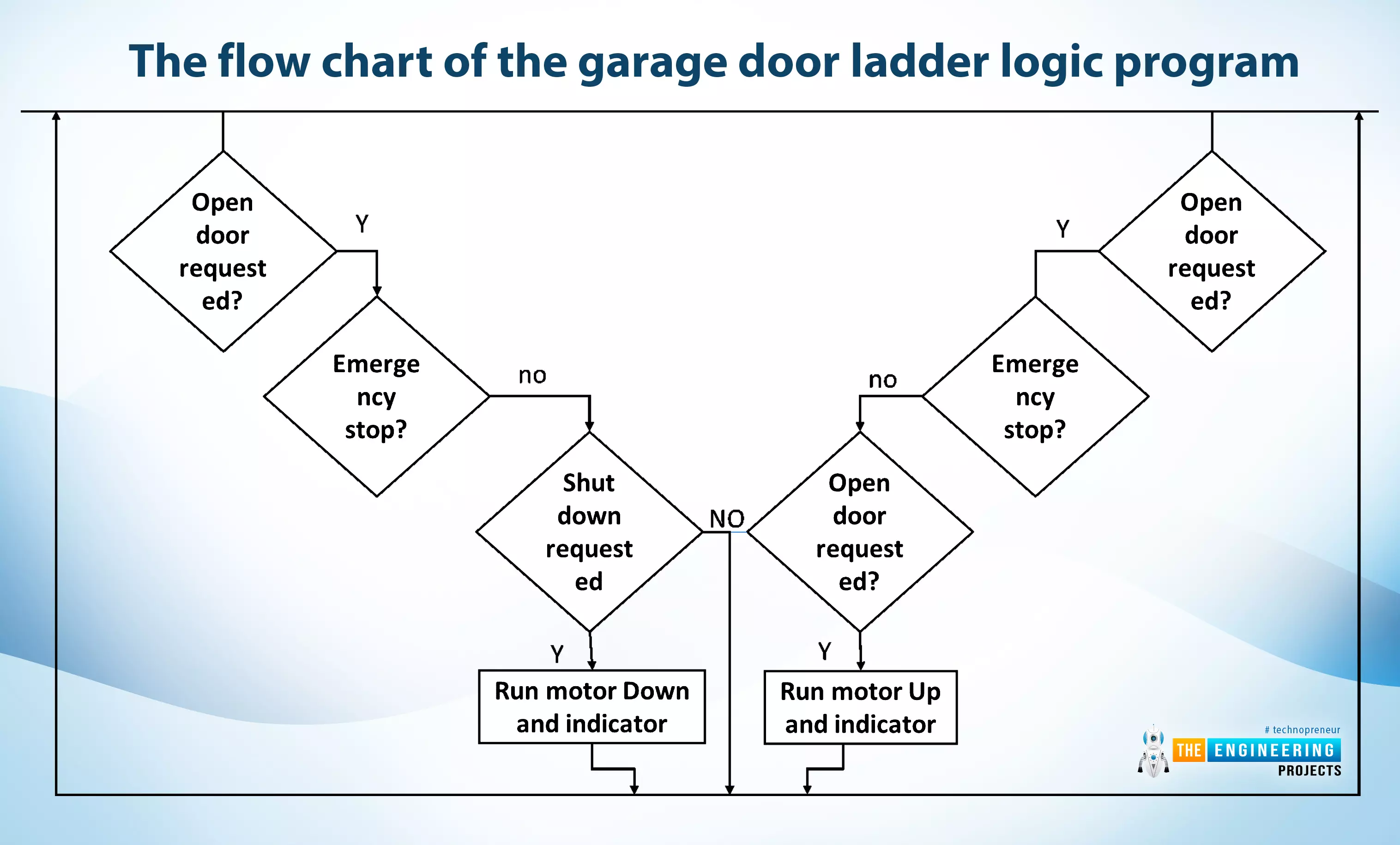
Despite this is a simple and short project. And it is our first complete project. We are going systematically step by step to show you guys the right sequence to achieve a ladder logic project work. Again, we have to sit with the customer to get his requirements, and then we interpreted his requirements into a logical narrative and decided on the IOs list and all system components. Now we need to work professionally and create a flow chart that represents the program logic graphically as shown in figure 3. It shows when a request of opening the door has been requested, it checks for any emergency stop or a concurrent stop request is in progress, if no then it is clear and all set to energizing the coil of the contactors that drives the motor to run in Up direction for opening the door right away. Similarly, when a request to shut down the door. The emergency stop is checked and if is there an open door request in progress if the answer is no then it is all the settings to run the motor in the down direction to close the door by activating the related contactor to energize the motor in the direction to shut down the door.
Ladder Logic Program
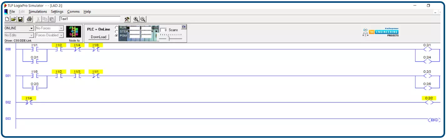
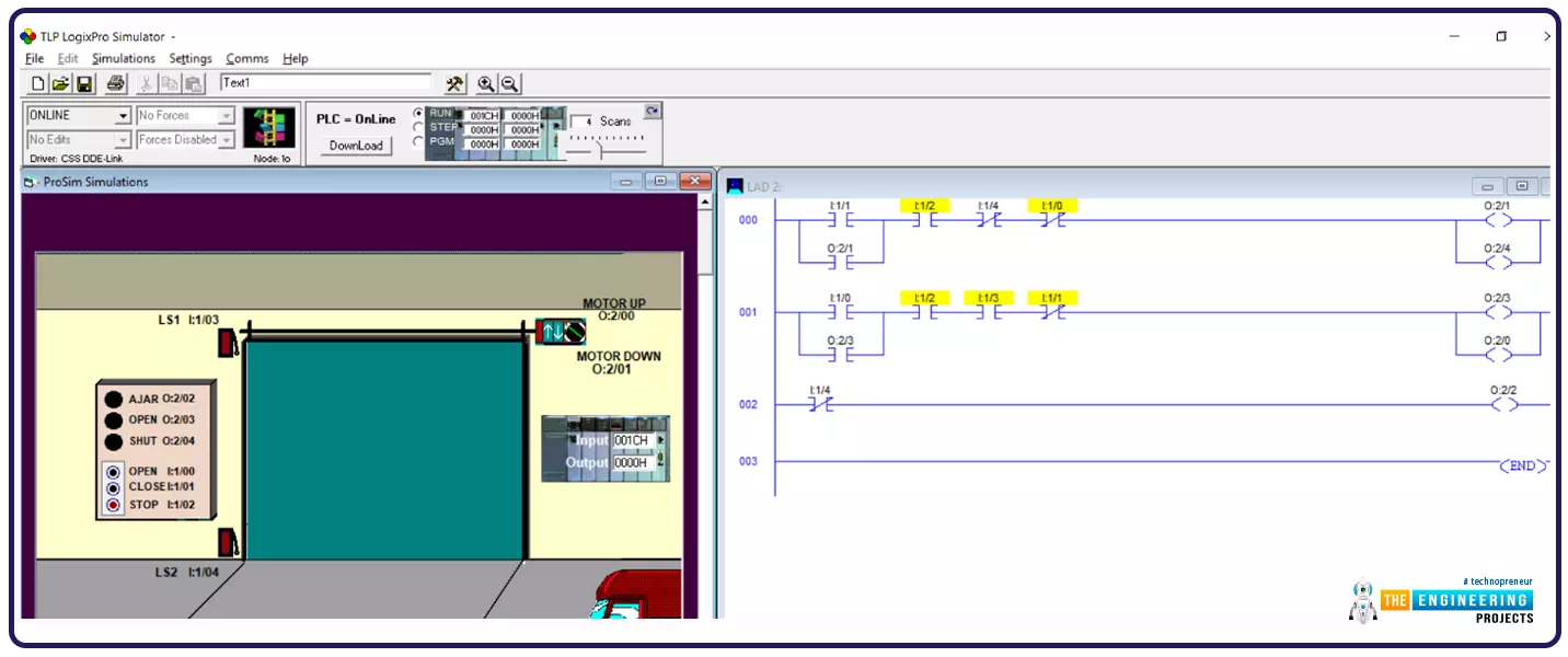
Now guys after completing the design stage in which we have to design the logic and decide on the system components and the logic flow. It is time to program so let my friends open our program editor and write down the program rung by rung based on the flowchart we just have drawn in figure 3. Looking into the ladder logic program, the first rung shows the opening handling request by energizing the output coils of the motor to run in the up direction and energizing the lamp indicator in case there is no emergency stop or a shutting down request in progress. Similarly, the second rung shows the shutdown request handling by activating the coils of the motor to run in the down direction and the indicator lamp to show the process of the shutdown of the door is in progress. That is true when there is no emergency stop is hit and no opening request is in progress. Also, you can see in both rungs for opening and shutting down the door of the garage that, the limit switches are used to prevent the door from opening or over closing for protecting the motors. At last, the third rung shows the indicator of ajar status as long as the door is not completely closed or when it is slightly opened.
Simulating the ladder logic program
Now guys! it is time to open our simulator to check if we already have written the correct logic or if there is something missed or wrong. Let me tell you something before testing your program you should hold and sit back and think about the test case scenarios for not to forget any case that might cause a failure to your program. For this very program we simulate, there are two main scenarios which are testing opening the door and testing closing the door. In addition to the main test case scenarios, there are edge test case scenarios which are testing requesting opposite operations like request opening while a shutdown process is in progress or requesting shutdown while an opening the door is in progress. Or testing requesting process while the E-stop is raised to check the safety of the operation. So let’s get started and take the test cases one by one to see if we have coded our program correctly or if there is an issue to fix.
Testing opening the door
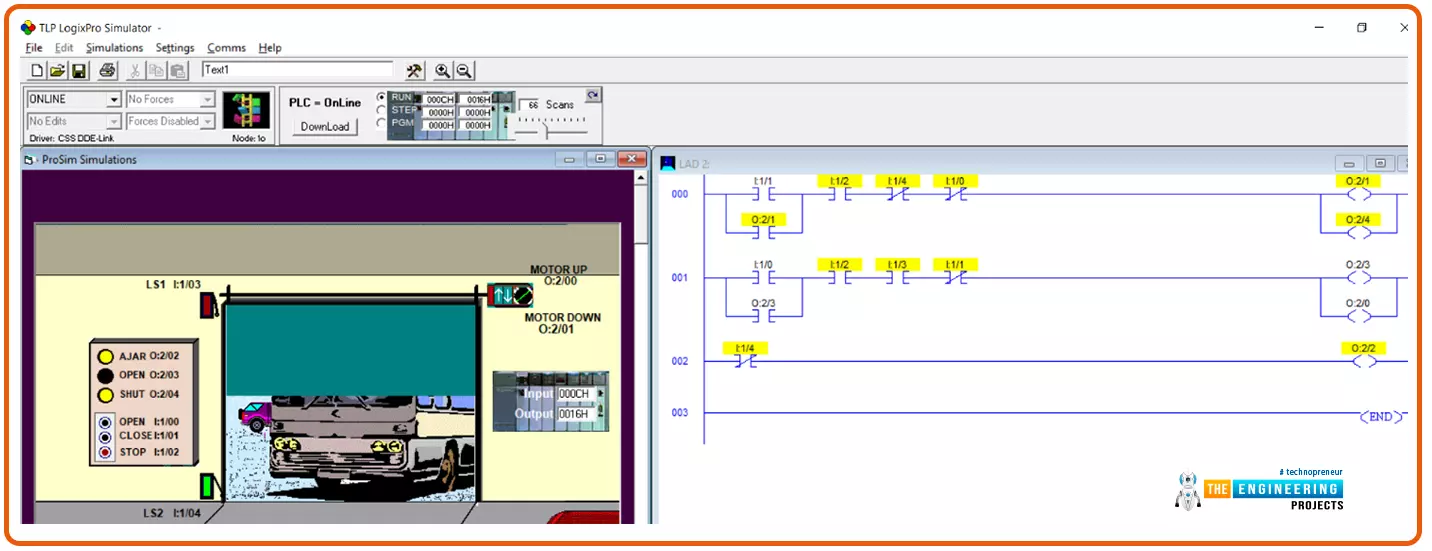
As you can see guys in Figure 5 in rung 2, the process of opening the door started by hitting the open push button, and because there is no emergency stop and there is no shutdown request in progress, the motor keeps spinning in the up direction and the opening lamp indicator keeps switched on. But up till when this operation will go on?
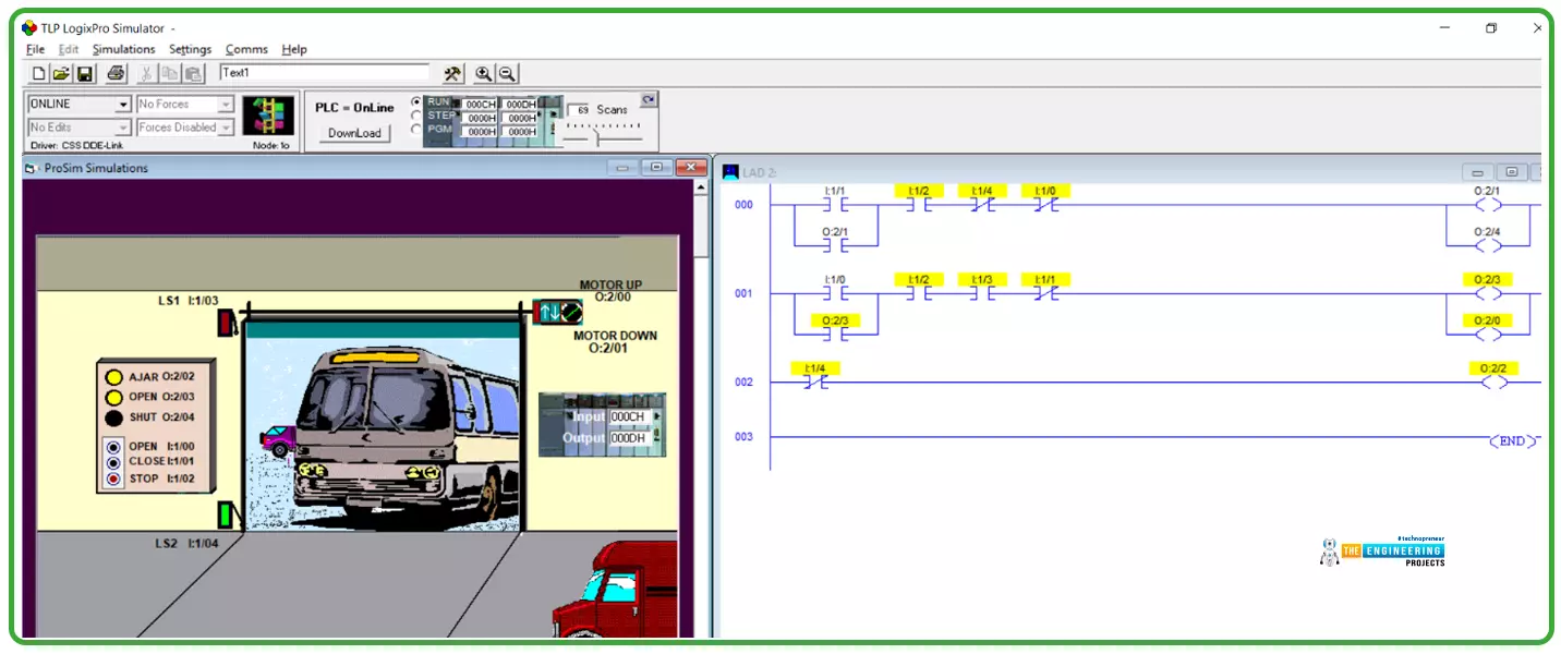
The process of opening the door is continued successfully until the LS1 is contacted at which the door has reached its final point for protecting the motor from overloading failure.
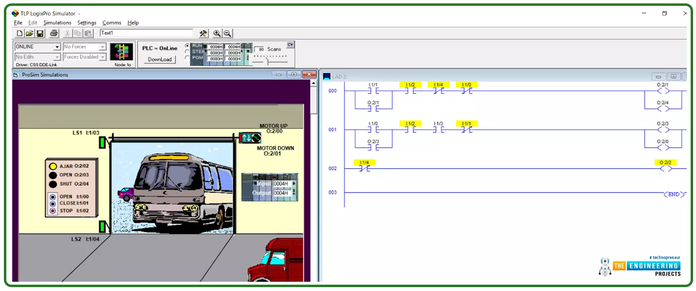
Also figure 7 shows the indicator of the door status on Ajar status whenever it is slightly opened or when it is not closed all the way.
Testing shutting down the door
Now let’s test the shutdown command by hitting the shutdown push button and notice the first rung in the program in figure 8. You can notice the door continues closing see the motor is spinning in the down direction and the indicator lamp showing closing is ON. But until when it will be stopped?
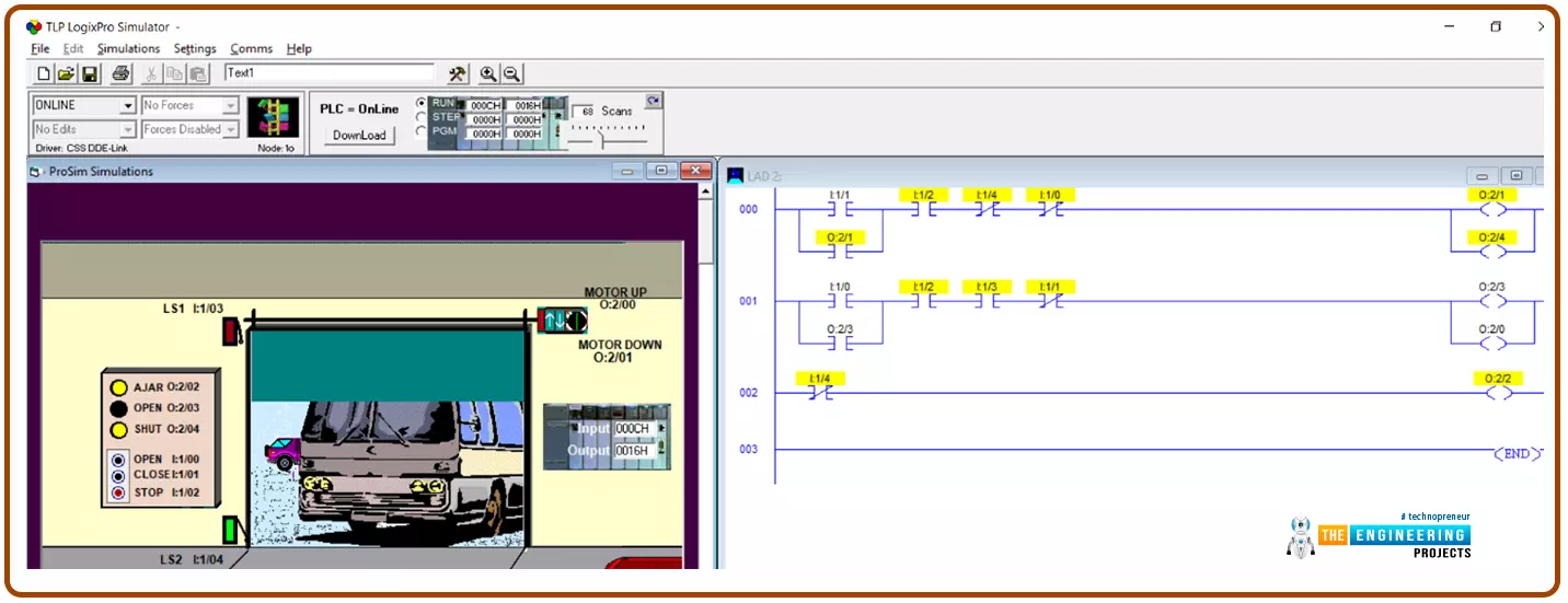
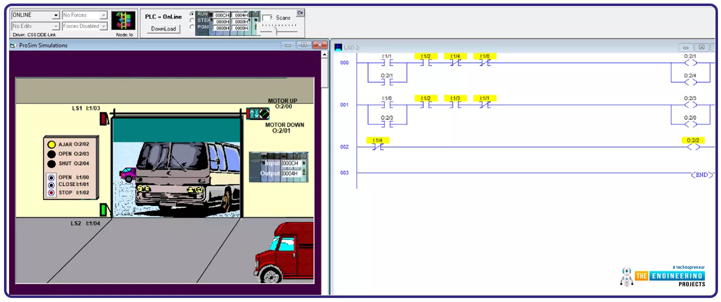
Figure 9 shows the end of the shutting down process of the door of the garage by having the limit switch LS2 reached that protects the motor from over spinning until it burned.
Testing requesting opposite operation while another is in progress
Figure 10 shows one of the edge test cases when the door was opening and all of a sudden operator requested to shut down the door. The test was successful and the operation can be reversed thanks at any time thanks to the good design by having the negative of each contact of the open and close in the other rung request as shown in rungs 1 and 2.
What’s next???
Guys! I would like to thank you all for sharing this tutorial up till this point hoping you all have enjoyed learning and practicing. And, be there with a larger project to take for the next time step by step learn, design, coding the ladder logic program, and enjoy simulating them as we are inside the factory.