


Bitwise Logic Operators in PLC Ladder Logic Programming


Hello friends, all of us know that PLCs are nothing but the smartest migration from relay logic control to programmable logic control. Also, you know clearly that, logic is the heart of any programming language, and the same is applied to ladder logic programming. Bitwise operators represent the logical operations including the basic logical operations like AND, OR, and NOT and the derived logical operations like NAND, NOR, and XOR. in most cases, for each bitwise operator, there are inputs based on which the output can be decided. Some of these bitwise operators have two inputs and some have only one input. In this article, we are going to present how we can use these bitwise logical operators and their instructions with examples and practice using the PLC simulator.
Logic Gates basics and concepts
Despite we have talked about these, basics and concepts in one of our articles, we have seen it’s good to remind you briefly that basic is the ground for your foot to stand coding logical operations in ladder logic programming. for defining a logical operation, there is a truth table that shows the combinations of the inputs and the resulting output. For example, the bitwise operator that has only one input like “NOT”, has only two possible value for input which is high or low, True or False. And it has one output which is the negate of the input. So it is either TRUE or FALSE. To sum up, for every bitwise operator instruction, we are going to discuss its truth table showing the states of the possible combinations of its inputs and the resulting output as well. In addition, one example using ladder logic programming shows the operation practically. We come to see it is important to list the bitwise operators in table 1 below shows the inputs, output, and the symbol of the logical gate that is equivalent to that bitwise operator.
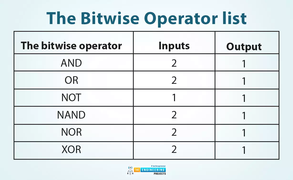
Table 1: the bitwise operator list
The bitwise operator |
Inputs |
Output |
AND |
2 |
1 |
OR |
2 |
1 |
NOT |
1 |
1 |
NAND |
2 |
1 |
NOR |
2 |
1 |
XOR |
2 |
1 |
AND bitwise operator
Guys, we can see the truth table of the AND instruction as tabulated in table 2. It shows the operator has two operands input A, and input B, and one output. The inputs can be switches, sensors i.e. limit switch for example while the output is a digital output to switch one actuator i.e. motor.
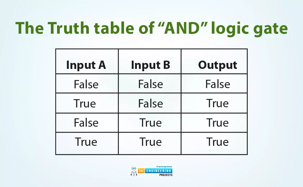
Input A |
Input B |
Output |
False |
False |
False |
True |
False |
False |
False |
True |
False |
True |
True |
True |
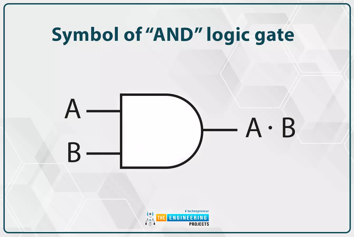
Also, Fig. 1 shows the symbol of the AND gate which is equivalent to AND bitwise operator. It shows two inputs A and B and only one output. Let us see that practically in ladder logic programming showing how to implement this with example.
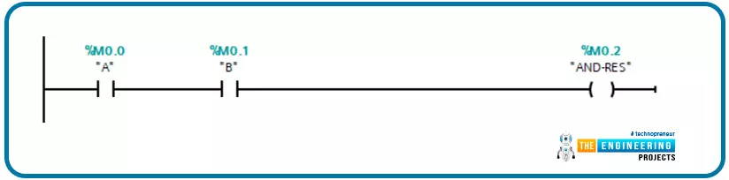
Bitwise Operator AND in Ladder Logic
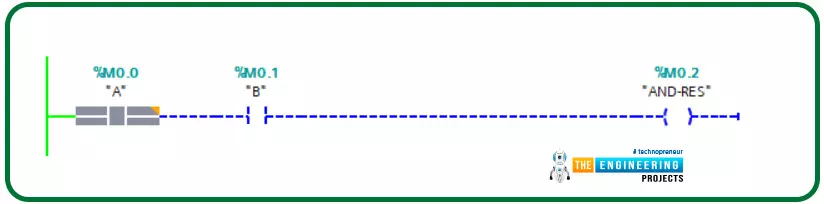
Figure 2 shows our first simple rung that codes the logic of AND bitwise logic. It shows two contacts A and B are connected in series to decide output AND-RES based on AND logic shown in truth table 2. So let us go .simulating this thing we just coded and see the logic in the application.
Simulating basic AND in ladder logic
We typically have 4 cases according to the truth table. Figure 3 shows the case when inputs A and B are low. The output shows low as shown by the coil AND-RES.
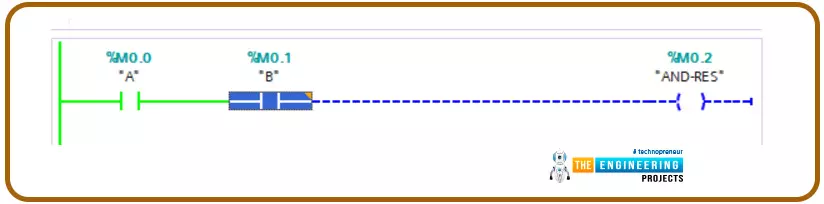
Now let us switch on input A and keep the second operand B false as shown in fig. 4, output AND-RES output still off.
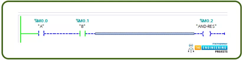
So let us try to switch the other input, B ON, and set input A off, as shown in fig. 5 output is off as represented by coil M0.2, tag AND-RES.
At last, when both inputs A and B are ON as in Fig. 6. Now only the output comes to turn ON.
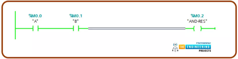
Guys!, you know for sure have got to know that, with AND logic, for having the output turned high both inputs A and B must be high.
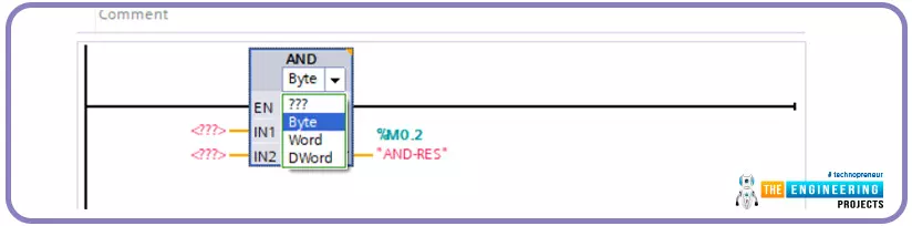
Ladder logic in Siemens and most other brands offer the facility to perform AND between byte, word, and Double word memory space as shown in Fig. 7 shows the AND block.
Simulate AND block in ladder logic
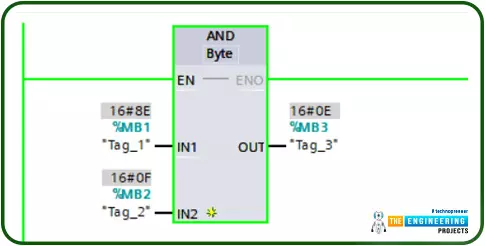
Figure 8 shows the usage of AND block for byte data type and it is possible to do the same with a word or double word data type. The instruction block applies to byte, word, and double word data types. However, for showing one example, Fig. 8. Shows the process of byte datatype. It shows the inputs A and B represented by memory bytes MB1 and MB2 while the output is represented by MB3. The operation shown in Fig, 8, can show the AND logic between two bytes that hold values “10001110” and “00001111” so the output represented by MB3 shows the value “00001110”.
OR bitwise operator
This logic gate has two inputs and one output like the “AND” gate. Like its name, the output comes true when either input A or input B comes true as shown in Fig. 4.
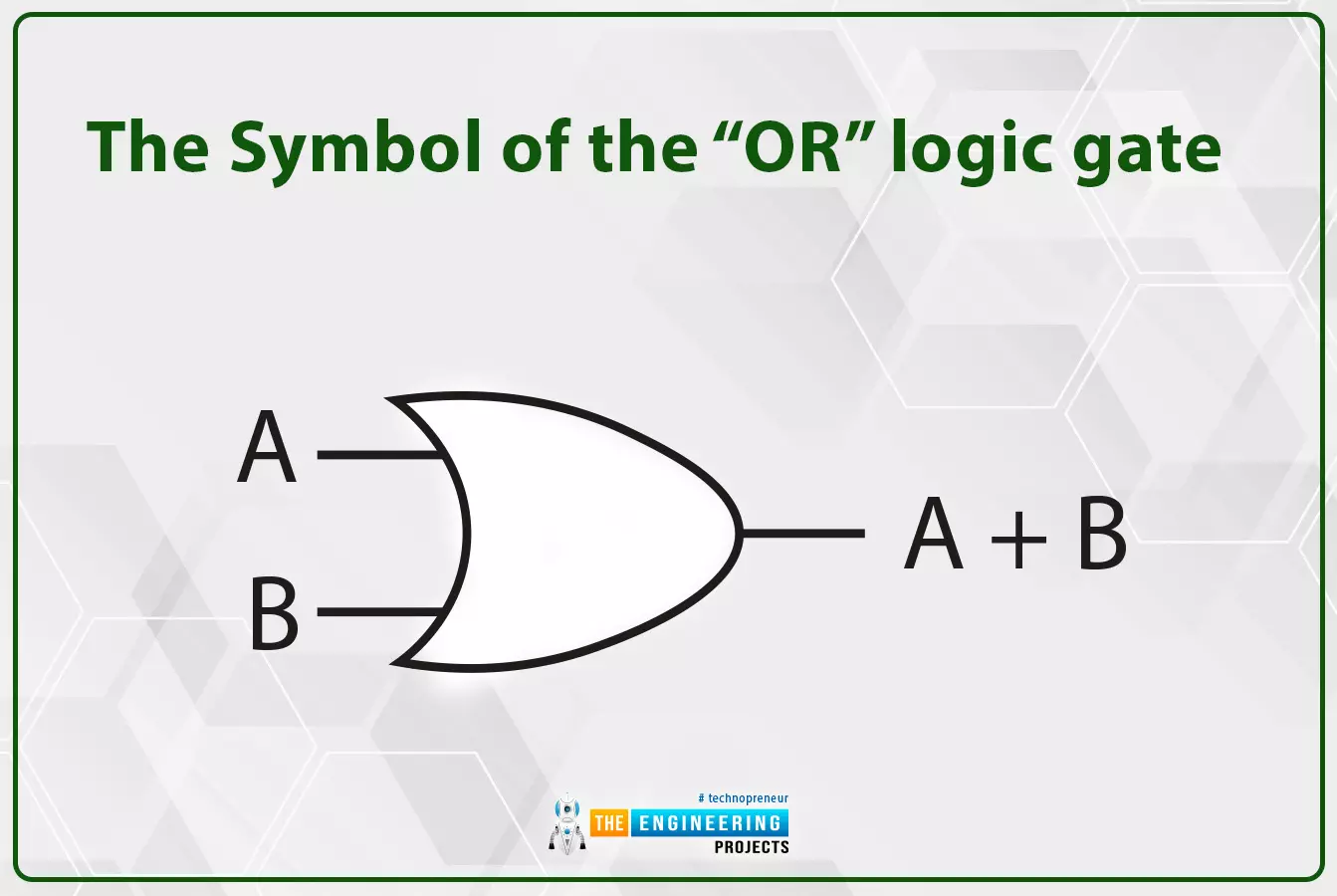
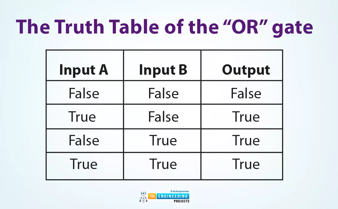
Table 3 lists the truth table of the “OR” gate. It lists all possible combinations of inputs and the output status as well. It shows that the output comes to true when input A or input B comes to true.
Input A |
Input B |
Output |
False |
False |
False |
True |
False |
True |
False |
True |
True |
True |
True |
True |
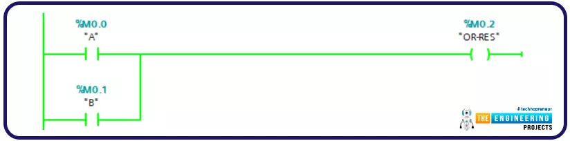
OR bitwise in ladder logic
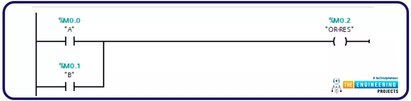
Figure 10 depicts the very simple rung of ladder logic that represents OR bitwise operation. It shows two inputs A and B connected in two parallel branches to give the output. So let us simulate that very OR code and apply the cases listed in the truth table in table 3.
Simulating OR bitwise operation in ladder logic
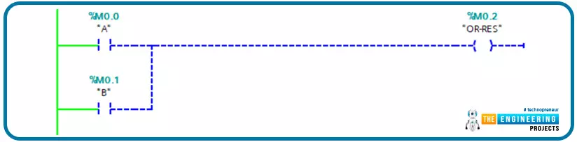
Typically as listed in table 3, the output is low when both inputs are OFF as shown in Fig. 11.
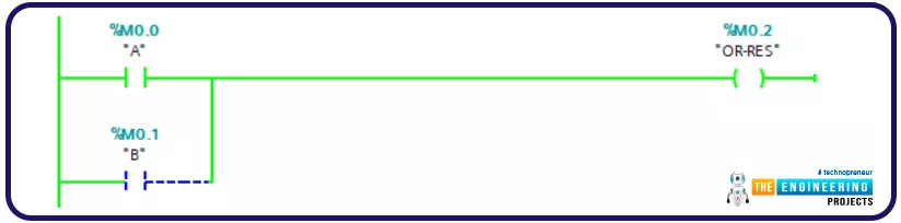
Ohh, you can see output comes ON when input A is ON and input B is OFF as shown in Fig. 12.
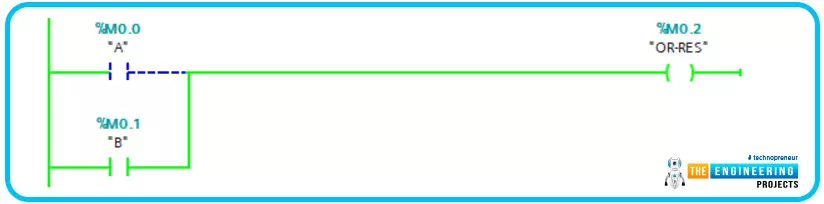
Also, output comes ON when input B is ON and input A is OFF as shown in Fig. 13.
Also, you can see output comes ON when both inputs A and B are ON as shown in Fig. 14.
That concludes two things guys, in OR bitwise logic, for having output ON, there must be at least one of the inputs High.
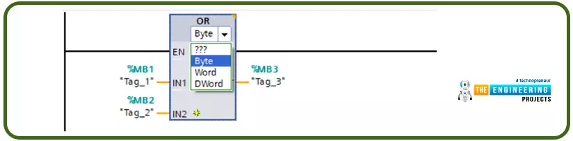
OR block in ladder logic
Ladder logic in Siemens and most other brands offer the facility to perform OR between byte, word, and Double word memory space as shown in Fig. 15 shows the AND block.
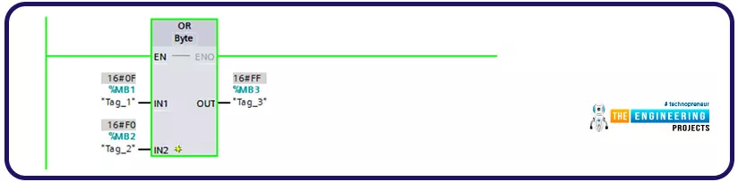
Simulate OR block in ladder logic
Figure 16 shows the usage of OR block for byte data type and it is possible to do the same with a word or double word data type. The instruction block applies to byte, word, and double word data types. However, for showing one example, Fig. 16. Show the process of byte datatype. It shows the inputs A and B represented by memory bytes MB1 and MB2 while the output is represented by MB3. The operation shown in Fig, 15, can show the OR logic between two bytes that hold values “00001111” and “11110000” so the output represented by MB3 shows the value “11111111”.
The bitwise “NOT”
This logic gate has only one input and one output. In a very simple language, the output is the inverted logic of the input. So when the input is true, the output would come to false and vice versa as shown in Fig. 17.
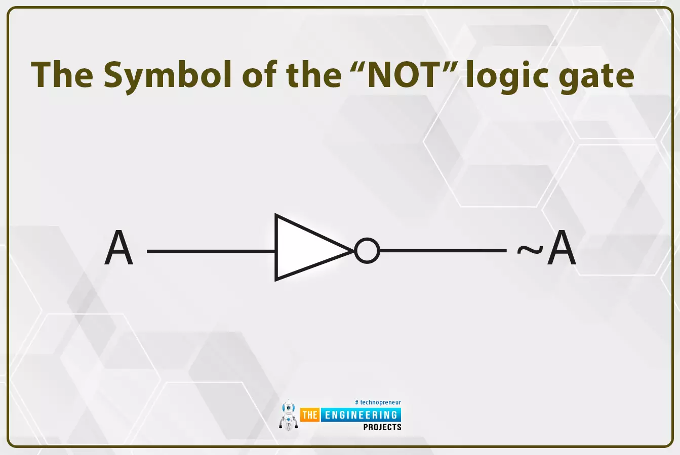
Table 4 lists the truth table rows of all possible combinations of input and output.
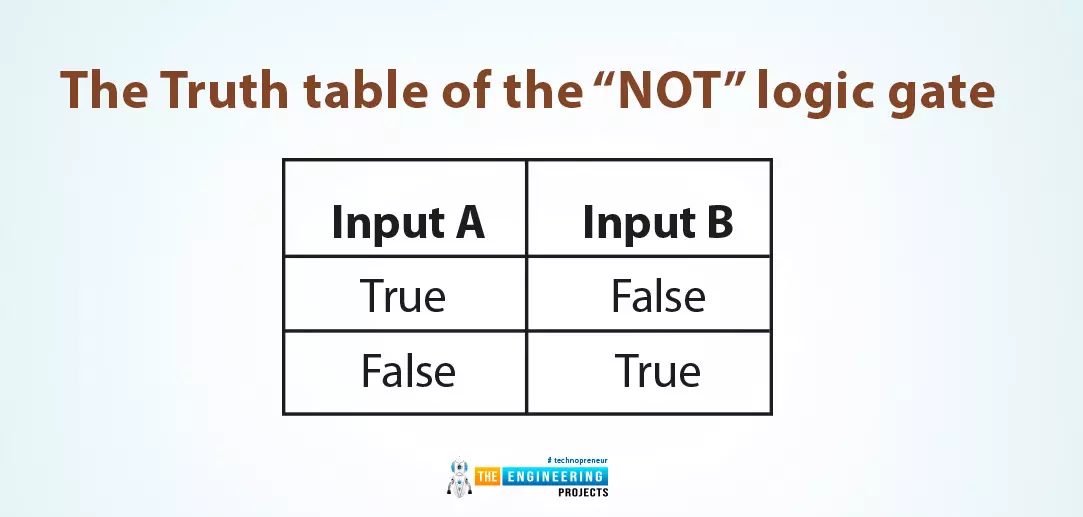
Input |
Output |
True |
False |
False |
True |
Figure 18 depicts a very simple example of a ladder logic rung that shows the output “NOT-A” is the negate logic of the input A.
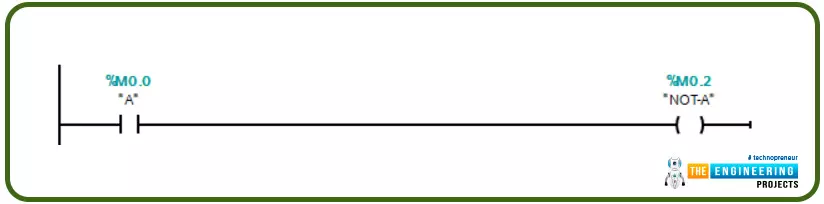
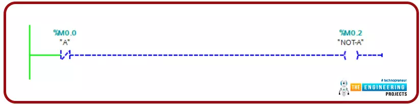
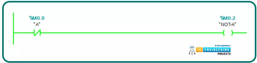
Simulating NOT bitwise in ladder logic
Now let's simulate the two cases listed in table 4 when inputs A is high and when it is low as well. Figure 19 and 20 show the output is the negate of the input using the NOT bitwise logic.
Now Guys we have gone through the basic bitwise logic. So how about the other bitwise logic that is formed by combining these basic bitwise operators like XNOR? let us simulate XNOR.
XNOR in ladder logic
XNOR is the negative logic of OR bitwise or you can name it as NOT-OR. Table 5 lists the combination of its two inputs and its output. It shows clearly that, the output becomes true when inputs are equal i.e. both inputs are true or both are false. Yes! Exactly, that’s why this bitwise operation is used when we need to compare two inputs if they are equal or not.
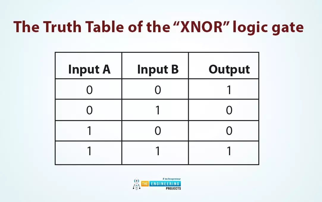
Input A |
Input B |
Output |
0 |
0 |
1 |
0 |
1 |
0 |
1 |
0 |
0 |
1 |
1 |
1 |
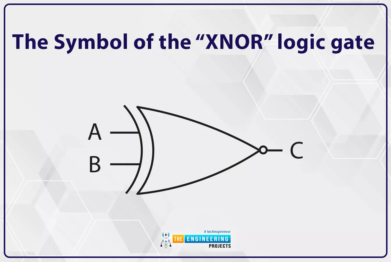
Figure 21 shows the symbol of the “XNOR” logic gate showing inputs and output of the bitwise operation.
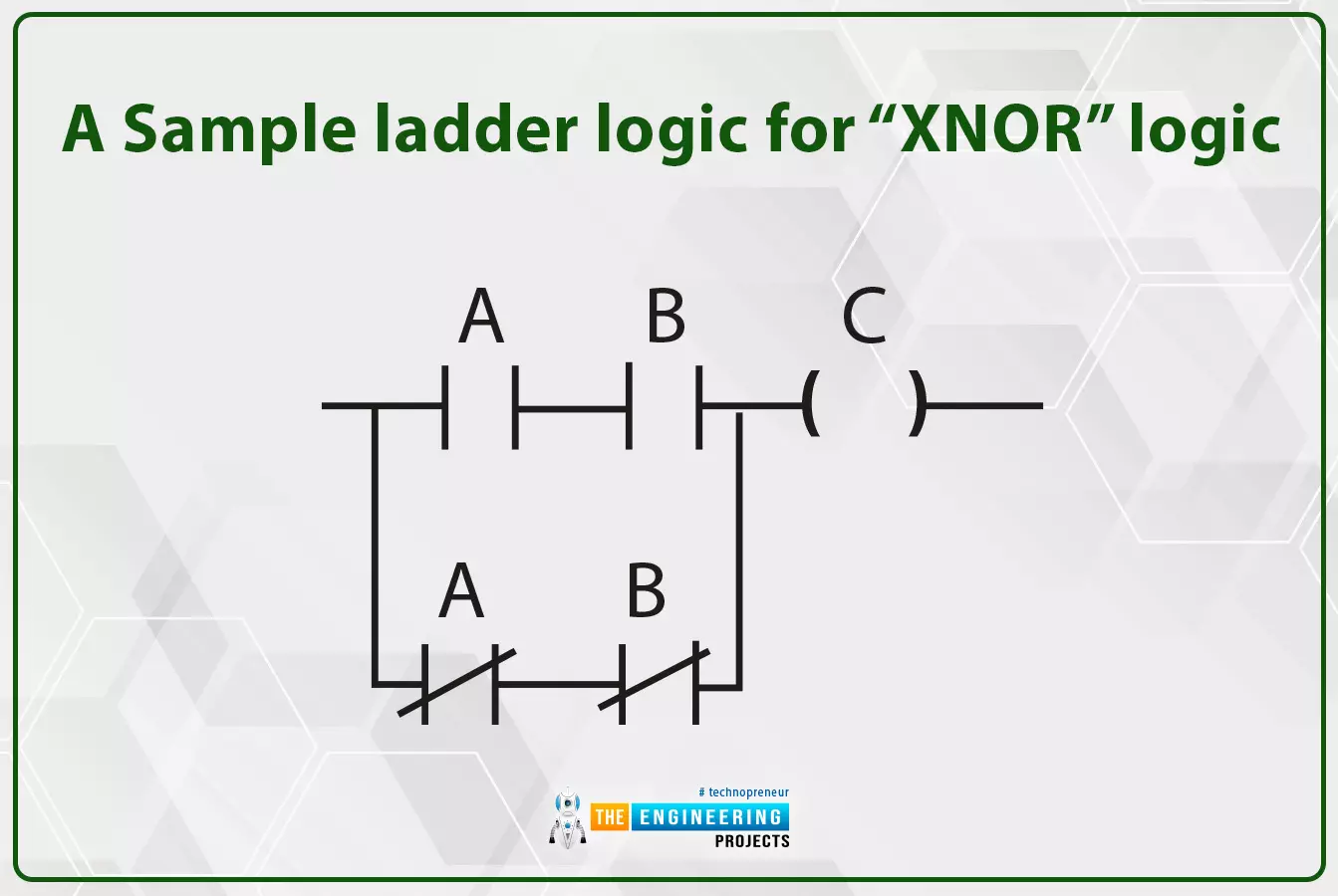
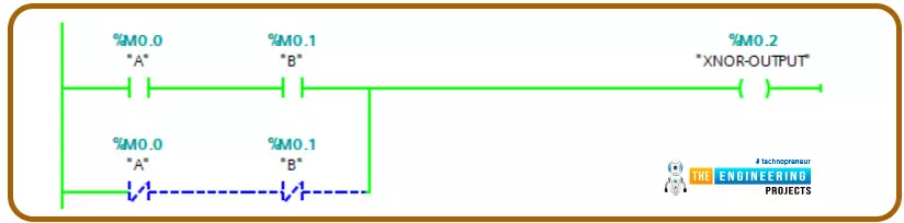
On the other hand, Fig. 22 shows a sample ladder logic of an “XNOR” logic gate implementation. It shows that there are only two ways to have the output in a TRUE state which are by set both inputs TRUE or setting both FALSE. So let us apply this to our simulator and test cases listed in table 5.
Simulating XNOR bitwise operator in ladder logic
Figure 23 shows the test of simulating XNOR when both inputs are low. You can notice friends that output comes to high.
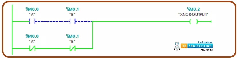
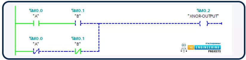
The same thing when both inputs are high, outputs show high as shown in Fig. 24.
Ohh, you can see when one input is not matched with the other that leads to low logic of the output. That concludes the XNOR gives a high logic output when only both inputs have the same logic; otherwise, it gives a low if they are different.
What next???
Before naming the next tutorial, I would like to let you know that there are many other bitwise operators like XOR, NAND, NOR, etc. this bitwise logic can be programmed in the same scenario we demonstrated above. Now, let me tell you that the next tutorial will be about one of the most important instructions ever in the PLC that will ease the data transfer between memory locations including all data types bytes, word, Dword, etc. it is the MOVE instruction in ladder logic. So be there to learn and practice that good one.


