Bottle Filling and Capping Project using PLC Ladder Logic


Hi friends, how are you doing? Today will integrate all of what we have learned so far in this series to build the first project based on ladder logic programming. Because we all are interested in industry, we pick one industrial project, Bottle Filling and Capping Projects, which is very common today. The problem we are going to solve today is bottle filling and capping. We have learned all basics of ladder logic including contacts and coils operation, logic gates, rising and falling edges, timers, and counters. So, today we will utilize all of these components to implement a complete ladder program of filling and capping problems.
Operation and Logic of Bottle Filling and Capping Process
For simplifying the operation of the process of filling and capping, fig. 1 shows the process flow which simply contains the main motor that drives the conveyor belt on which the bottles are running starting by hitting the start button. The conveyor belt starts running driven by motor M1 and the bottles move until sensor S2 detects one bottle, then motor M1 stops and the belt does so. At the same time, valve V1 opens to let water get dropped into the bottle until it reaches specific level thanks to level sensor S1. Then valve V1 closes and motor M1 goes on moving. Then when sensor S3 sees a bottle, the piston P1 is activated for capping the bottle and so on.
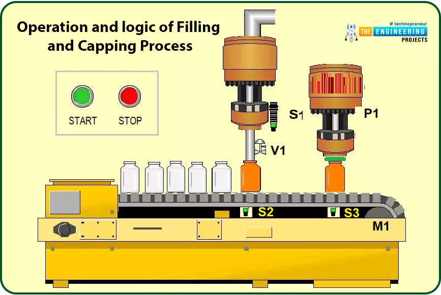
Fig. 1. The Filling and Capping Process
Process Inputs and Outputs
As you can see, for every single process in the industry, there are inputs and outputs. The inputs represent the sensors and user requests like starting and stopping the process. While the outputs are represented by actuators like motors, valves, and pistons. Table 1 lists the inputs and outputs of the filling and capping process. It shows the process consists of four inputs and three outputs including the function and description of each item.
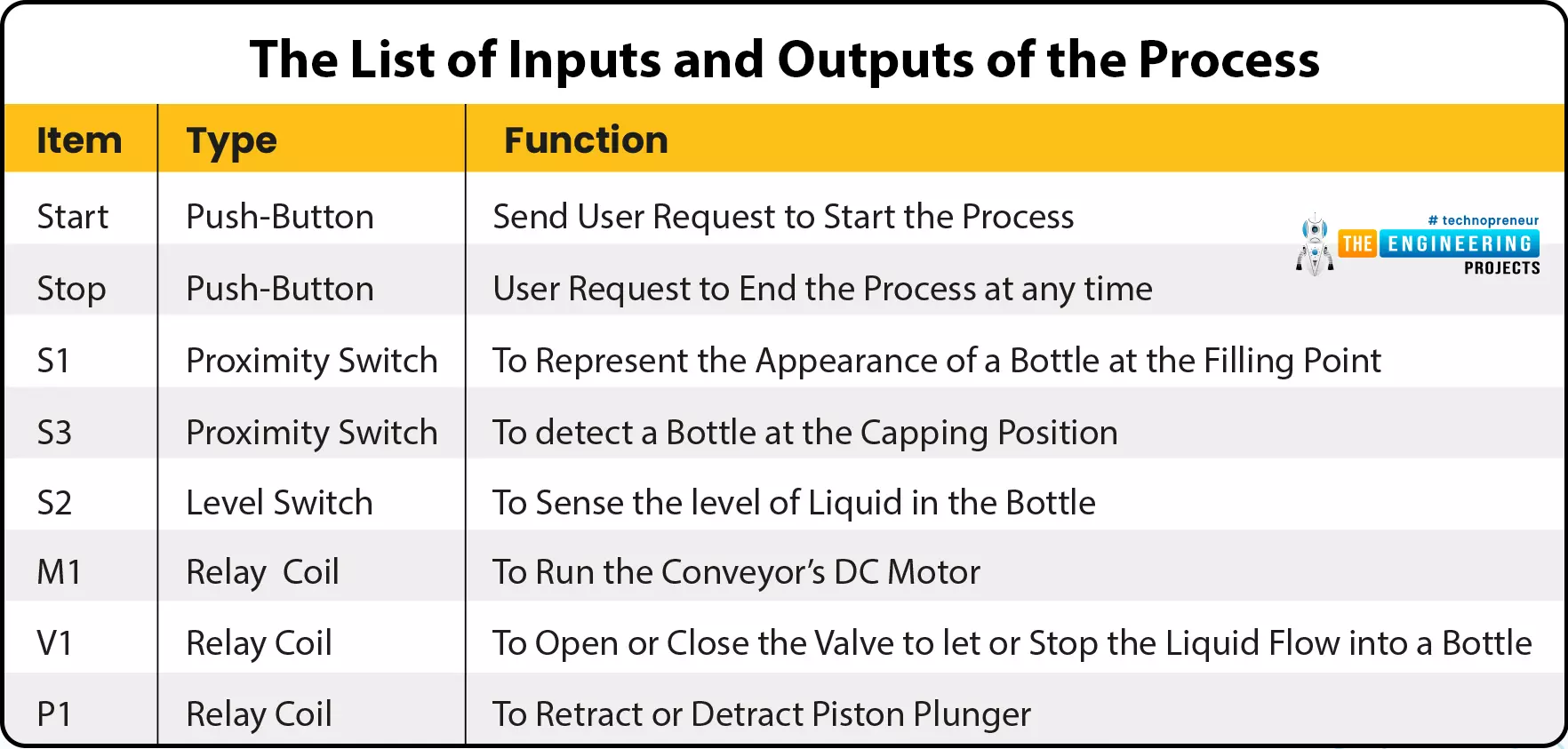
Table 1: The list of Inputs and outputs of the Process
Logic Design of the Operation
Before going to ladder programming, we should design the logic of the operation to build guidelines on which we can develop the ladder logic. According to the operation description we stated aforementioned above, we can express the logic in lines as follows:
- If start is ON, no filling is in progress meaning sensor S2 does not see a bottle, and no stop is requested, then motor M1 is ON.
- If sensor S2 is ON, that means there is a bottle at a position to be filled so motor M1 will be stopped or OFF.
- If sensor S2 is ON, that means a filling process is in progress, therefore, Valve V1 will open
- If S1 is ON, that means the liquid in the bottle that is being filled reached the maximum level, So valve V1 closes and motor M1 now goes on running.
- If S3 is ON, that means there is a bottle that presents at the capping station, So the piston P1 is retracted to process the capping of the bottle.
As you see in these few lines, we just wrote the philosophy of the filling and capping process’s logic. And the process keeps repeating until user requests stop. So now let’s move to convert this written logic into ladder logic rungs and enjoy for sure simulating the process in our lab to verify the logic we designed is correct or we need to amend.
Ladder Logic of Bottle Filling and Capping System
Before getting starting the filling and capping programming, we need to design the list of inputs and outputs of the program and their initial states. Table 2 shows a list of the inputs and outputs with their addresses and initial states.
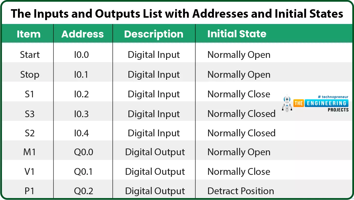
Table 2: The Inputs and Outputs list with Addresses and Initial States
Figure 2 shows the first network in the designed ladder program. My friends, do not feel it a complicated because the fact is that, it is really simple. First of all, the start button to run the conveyor belt motor coil and latching is considered for letting the belt resumes running even after releasing the start button. Also, you should ask yourself during design two questions. The first is when the motor of the conveyor belt will be running and when to stop it? The answer to these two questions will end up with completing this network. For instance, the first question which inquiries about when to start the conveyor belt can show that the belt should be running by hitting the start push button to represent the request of the user to run the process. But, while the filling process is in progress marked by the activation of sensor S2, the conveyor should stop waiting for the filling process to complete by closing the valve when reaching the filling level limit noted by sensor S1. So, closing the valve is another signal that starts the conveyor once again. On the other hand, the conveyor belt should stop when the stop is requested by the operator in addition to sensor S2 that indicates a presence of a bottle in the filling station. So, you can notice two parallel branches to run the conveyor belt, one by start push button and one for latching. In addition, another parallel branch is added to run the belt by showing the completion of the filling process thanks to the signals of valve V1 status.
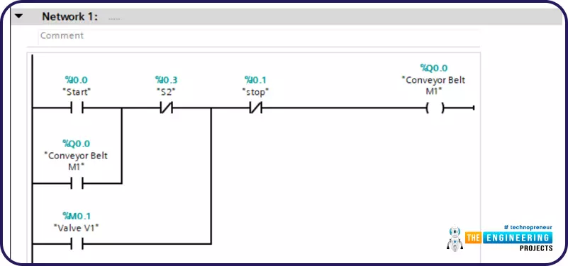
Fig. 2: Ladder Logic Network 1
Now, let’s have a look at the valve and ask ourselves the same question as what we have done with the motor of the conveyor belt (M1). what makes the valve V1 get closed and what causes it to open? For those causes to open the valve are the signal of sensor S1 that tells the bottle that is being filled is already filled and all set to move to cap station in addition to the latching consideration. So, we have two parallel branches, one branch for the sensor S1 and the other one from the valve status contact for latching. Those parrel branches connected in series to show “AND” logic with the sensor S2 to make sure of the presence of a bottle in the filling station. On the other hand, the stop push button represents an ending request received at any time from the user to close the valve.
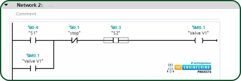
Fig. 3: Ladder logic network 2
Now, the process goes on and the bottle has just left the filling station and has reached to capping station. That has been recognized thanks to sensor S3 that detects a bottle that has just arrived at the capping station. As a result, the piston should be activated. Firstly, a timer has been utilized to let the piston activated for some amount of time that is enough to let the capping process be comfortably completed. So, in-network 3 shown in fig. 4, a timer which is of off-delay type is utilized to activate the capping piston for plenty of time to let the capping process be completed as shown in fig. 5.
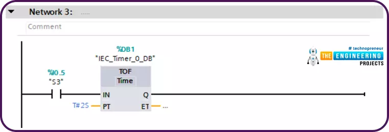
Fig. 4: Ladder Logic Network 3
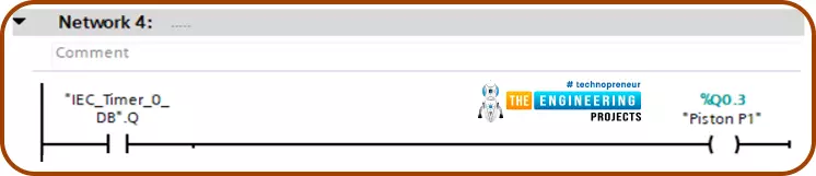
Fig. 5: Ladder Logic Network 4
And finally, in-network 5 shown in fig.6, the falling edge signal of the piston denotes the completion of the capping process. So, a counter which is of type count-up timer is triggered to count up to determine the number of the processed bottle so far. The preset value has been set to a specific value i.e. 100 which can be used to perform maintenance or end a batch process for 100 bottles to be filled and capped.
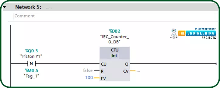
Fig. 6: Ladder Logic Network 5
Compiling the Ladder Logic of the Project
After translating the writing logic to a ladder program that is composed of a couple of rungs, the second compulsory step is to verify the syntax of the ladder program and make sure that the program is free of error. So, we show you in fig. 7 the compilation results to show there is no error with the written code so far. By doing this verification, we are all set now to upload the program to the controller and check the logic and operations.
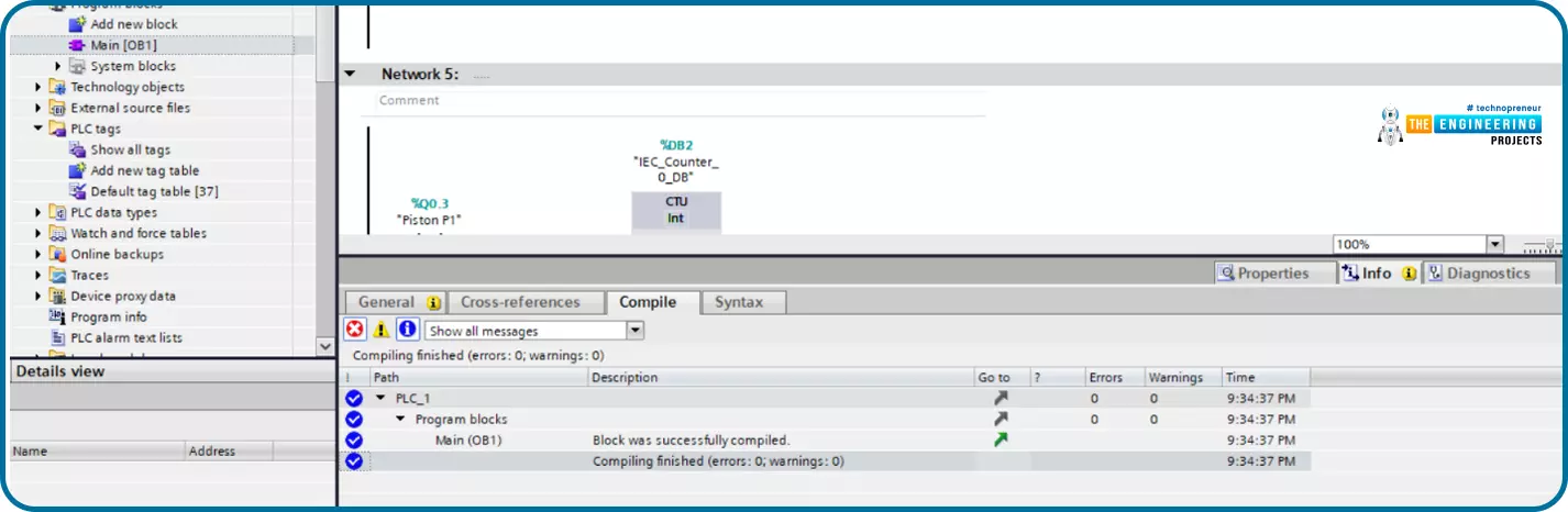
Fig. 7: Compiling the Designed Ladder Logic Program
Simulating and Testing
It is time to go to our lab and open the simulator to check the design and written ladder code. Figure 8 shows the initial state of the program before starting the process. It is clear that the conveyor belt is stopped and the status of all sensors, pushbuttons, actuators are as their aforementioned initial states.
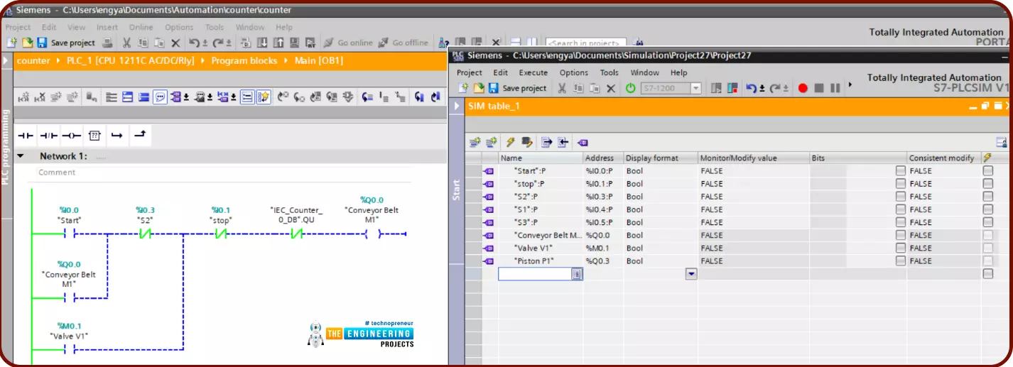
Fig. 8: Initial State of the Inputs and Outputs Before Starting the Process
Now, let’s hit the start push button to start the process and watch what is going on. Figure 9 shows good news!!! By hitting the start button, the process correctly started and the motor M1 that drives the conveyor belt starts spinning. But, how about checking to release the start pushbutton by leaving our hand to see what’s going on?
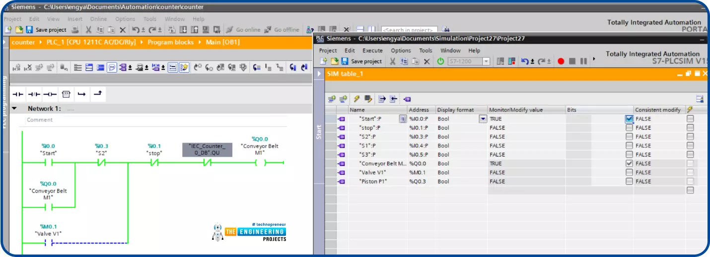
Fig. 9: The status After Hitting Start the Process
WoW!!, well done, latching is working as shown in fig. 10 as the conveyor continues spinning even after releasing the start button thanks to applying the latching technique.
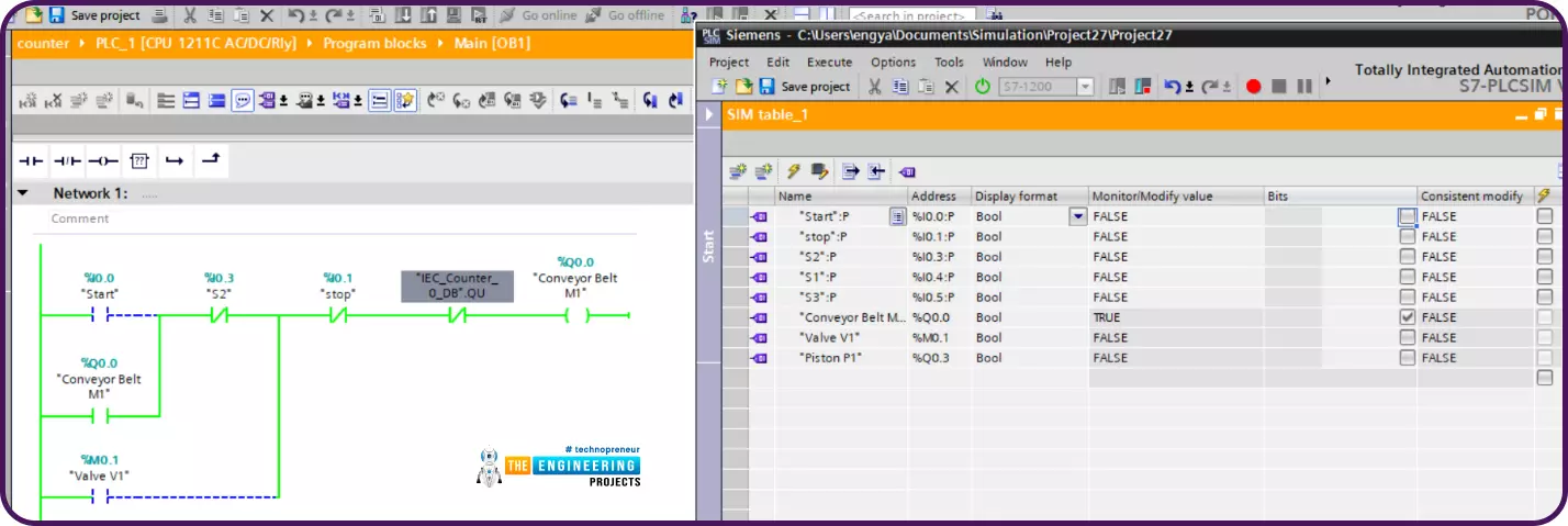
Fig. 10: Conveyor Still Running Even after Release start Push Button Thanks to Latching
Once a bottle is presented at the filling station, sensor S2 is activated. Consequently, the conveyor stops waiting for the filling process to complete. But, when does the filling process ended and how to know it’s done already to go further?
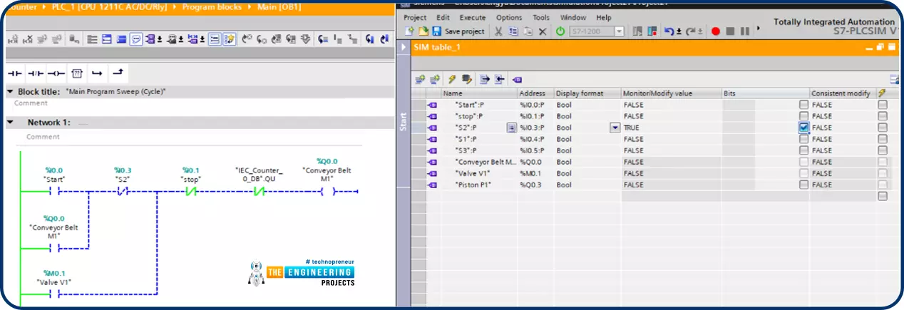
Fig. 11: Conveyor Stops when a Bottle Presents at S2 for Filling
Well! Sensor S1 is there to watch the level to which the liquid reaches in the bottle that is being filled. Once the limit is reached, sensor S1 is activated telling hey here we go, the filling process is over and now we ready to go further to the next step which is the capping station as shown in fig. 12.
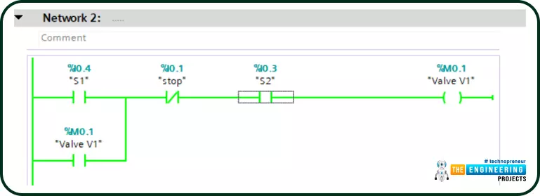
Fig. 12: The Valve is Closed by reaching the Limit Level and S1 is ON
Because the valve is closed after the filling limit is reached, the conveyor continues spinning and sensor S2 is deactivated showing the bottle has been filled and left the filling station. However, the conveyor belt keeps running thanks to the latch again as shown in Fig. 12.
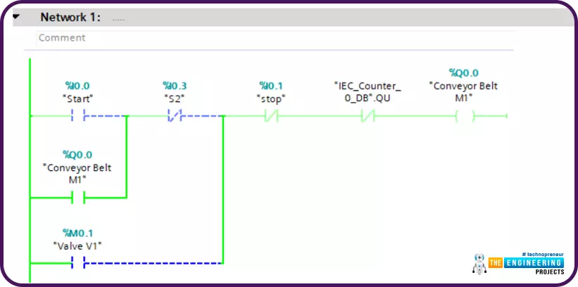
Fig. 13: The Conveyor belt Goes Running by Closing The Valve V1
Let’s now my friends check what’s happening by reaching the capping station? Astonishing !!! as we put there our agent to tell us a bottle has arrived for capping which is sensor S3, once that happened, sensor S3 is activated and hence activates the piston to retract and keep retracted for a sufficient amount of time to let the capping process be completed thanks to using a timer of type off-delay timer. So first fig. 14 shows in network number 3, the timer is activated and starts counting the time that is preset to 2 seconds and in the same time activates the piston to keep retracted during that time based on the nature of operation of an off-delay timer.
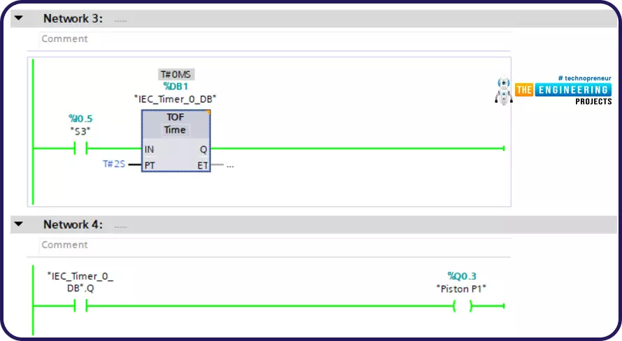
Fig. 14: The Piston is Activated by Reaching at Capping station When S3 is ON
And finally, the counter is utilized to count the processed bottles which are triggered by the falling edge of the piston denoting completion of a filling and capping process.
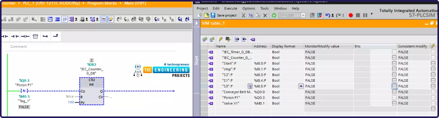
Fig. 15: The Counter Counts up Every item After the Capping Process
What’s next
By reaching this line in our tutorial, I would like to congratulate you that you are now all set to think about complete basic problems in the industry and design the logic to solve them and write the ladder code. Is here the end station of our ladder logic tutorial? For sure no, we still have a lot to move forward from the basic level to become experts. So wait for the next tutorial in which we go deeply into details of math and logic functions and data processing.