Move Instruction in Ladder Logic Programming


Hi friends, today we are going to learn one of the most important instructions in the PLC ladder which is MOVE instruction by which we can move data between different memory storage including input, output, marker, and variables. Also, data of different data types and sizes can be transferred from source to destination and source memory locations. For example data types including char, string, integer, floating, time and date can be transferred between source and destination. Memory location like input, output, and marker memory area can be acting as source or destination. Furthermore, a mask can be utilized to customize and control the part of data to be transferred between source and destination. In that move with a mask, the instruction uses a source address, a destination address, and the mask as well. Guys, please do not worry if you are not understanding what is mentioned hundreds percent because you will get it in more detail and practice with the simulator as well. So let’s continue to learn and practice that MOVE and masked MOVE instruction.
MOVE Instruction in Ladder Logic
Let’s start with the basic MOVE instruction. Figure 1 shows the typical block of a MOVE instruction in Siemens. It shows two sides for the input and output parameters of the block. Simply, the input EN input shows the contact that enables the block and triggers the movement of data between the source specified by the memory address given at input IN and the destination pointed by the memory address given at output OUT1. Also, output ENO denotes the status of the movement process to indicate the completion of the process.

Source and destination of the MOVE instruction
As shown in the function block of the MOVE instruction shown in figure 1, there are source and destination which are an address of a memory area and can be expected to be byte, word, or double word DWORD or of any datatype like integer, character string, float, time, or date datatype. Some examples of memory size and datatype are listed in table 1 below:

Source (IN) |
Destination (OUT1) |
|
|---|---|---|
With IEC check |
Without IEC check |
|
BYTE |
BYTE, WORD, DWORD |
BYTE, WORD, DWORD, SINT, USINT, INT, UINT, DINT, UDINT, TIME, DATE ,TOD, CHAR |
WORD |
WORD, DWORD |
BYTE, WORD, DWORD, SINT, USINT, INT, UINT, DINT, UDINT, TIME, DATE, TOD, CHAR |
DWORD |
DWORD |
BYTE, WORD, DWORD, SINT, USINT, INT, UINT, DINT, UDINT, REAL, TIME, DATE, TOD, CHAR |
SINT |
SINT |
BYTE, WORD, DWORD, SINT, USINT, INT, UINT, DINT, UDINT, TIME, DATE, TOD |
USINT |
USINT, UINT, UDINT |
BYTE, WORD, DWORD, SINT, USINT, INT, UINT, DINT, UDINT, TIME, DATE, TOD |
INT |
INT |
BYTE, WORD, DWORD, SINT, USINT, INT, UINT, DINT, UDINT, TIME, DATE, TOD |
UINT |
UINT, UDINT |
BYTE, WORD, DWORD, SINT, USINT, INT, UINT, DINT, UDINT, TIME, DATE, TOD |
DINT |
DINT |
BYTE, WORD, DWORD, SINT, USINT, INT, UINT, DINT, UDINT, TIME, DATE, TOD |
UDINT |
UDINT |
BYTE, WORD, DWORD, SINT, USINT, INT, UINT, DINT, UDINT, TIME, DATE, TOD |
REAL |
REAL |
DWORD, REAL |
LREAL |
LREAL |
LREAL |
TIME |
TIME |
BYTE, WORD, DWORD, SINT, USINT, INT, UINT, DINT, UDINT, TIME |
DATE |
DATE |
BYTE, WORD, DWORD, SINT, USINT, INT, UINT, DINT, UDINT, DATE |
TOD |
TOD |
BYTE, WORD, DWORD, SINT, USINT, INT, UINT, DINT, UDINT, TOD |
DTL |
DTL |
DTL |
CHAR |
CHAR |
BYTE, WORD, DWORD, CHAR, Character of a string1) |
WCHAR |
WCHAR |
BYTE, WORD, DWORD, CHAR, WCHAR, character of a character string1) |
MOVE instruction in ladder logic
Figure 2 shows one very basic ladder logic rung that demonstrates the usage of a MOVE instruction. It consists of a contact “trigger” to control activation of the move instruction, the MOVE instruction block which has source and destination memory address MW10 and MW12 respectively. The source and destination in this example represent integer data types.

Guys! Let's simulate this rung to learn together how the MOVE instruction works. Figure 3 shows the case when the MOVE instruction is not activated, in that case as shown in figure 3 the data is not transferred from source to destination.

But after activating the MOVE instruction by enabling the EN of the MOVE block using the contact M0.1, the data is moved from the sources to the destination.

It is important to let you guys know, this MOVE function block can be used to move different types of data types as listed above by providing the address of both source and destination.
Massive move instruction using ladder logic
Friends! Sometimes we need to move arrays of data. So do your think we are going to move one by one? The answer is yes it is possible but that is too boring to code and the program is getting very lengthy. So there is another version of MOVE instruction that enable us to move a massive amount of variables which is MOVE_BLK instruction. Figure 5 shows the function block of the massive move instruction in a very basic example ladder logic rung. As you see friends, similar to basic MOVE instruction, it has EN and ENO for enabling the instruction and returning its status showing the completion status. Also, it has an input source denoted by the address of the memory storage of the source and the address of the memory location of the destination as well. But you notice that time there is an array of variables or datatypes for source and destination. And there are other parameters called count which denotes the number of items to be moved from source to destination. Let’s simulate this MOVE_BLK instruction to see how it works and the virtues of moving many data items in one command.

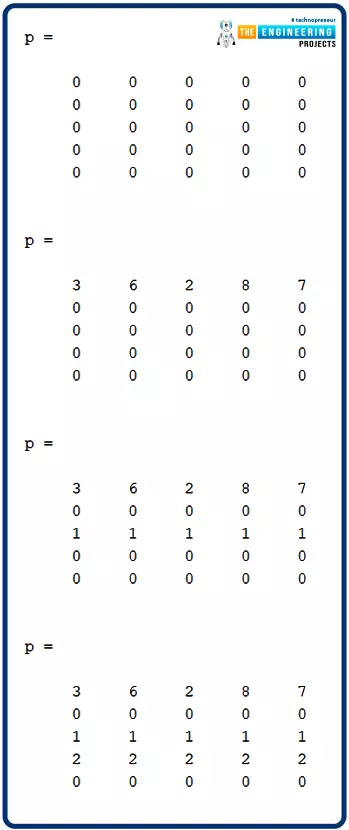
Figure 6 shows the execution having the block not activated. On the right part the memory of the source and the destination show array of 5 integers for each. You can notice guys there is no data moved.

Figure 7 shows the data is moved from source to destination after activation of the MOVE_BLK instruction. But wait for a second! Why not all the data been moved? Yes, you are correct friends, because we use count parameters to control how many variables or data items are to be transferred. And it has 3. So the first three data items have been moved only.

MOVE instruction in Allen Bradley
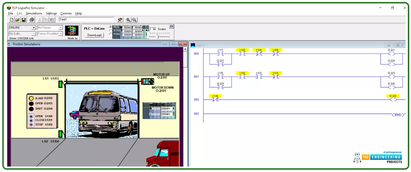
Figure 8 shows a simple program that demonstrates the ladder logic rung that uses MOVE instruction. It shows the input contact I:3/0 triggers the move instruction block to activate it and enable data transfer from the 16bits input I:1 to the 16bits output O:2. On the left side, you can see guys the inputs are mirrored at the output by using the MOVE instruction. Now let’s see how we can control the data transfer using a mask to allow only selected bits to be transferred and prevent the others.

Masked move instruction
The idea behind the masked move instruction is that we utilize an array of bits to be used as a mask to filter the data that are being transferred. For example Figure 9 shows a very simple ladder logic rung that uses a masked MOVE instruction to customize the data transfer from source to destination. The MVM instruction has three parameters as shown in figure 9 which are: the source, destination, and mask. All of them are addresses of the memory area. For the very given example here, the source is the 16 bits input at I:1/0 and the output is the 16 bits output at O:2/0 while the mask is the 16bits input at I:3/0. Before we are going to simulate this example, you should expect that the data will be transferred from source to destination based on the status of every bit in the mask data.

Simulating masked move instruction
In the first test case shown in figure 10, the data to be transferred is ready at the source but nothing is transferred to the destination because the activating contact I:3/0 is not enabled. So let’s switch it on and see what is happening!

Now we enabled the activation switch at I:3/0 but still, data are not transferred from source to destination! Is there a problem in coding or logic? No, that is because the mask bits are set to off that is why bits of the source are not enabled to be transferred to the destination. Now, let us enable the masked bits and see what’s going on?

Yes! Now guys you can see all bits of the source have been transferred to the destination as long as their mates at the masked bits are enabled. But those who have their mates of bits at the mask are disabled and are still prohibited from being transferred. Like this, you can see friends how we can move data without control as when we use the MOVE instruction. In addition, you see how to control that data transfer by using mask bits as a filter. Do not forget, the move instruction can be utilized to move different data types, variables, memory sizes, and data blocks. So, it is a great tool for you as an experienced ladder logic programmer to flexibly move data between your data variables and memory location through long the program you are writing.

What’s next???
Guys! I would like to thank you for being here with me up till this point of our tutorial hoping you are really happy with it and seeing it is useful. Now guess what? I have a gift for you which is our next tutorial. It is not like every time we come up with another aspect in ladder logic to learn and enjoy practicing simulation. Now we come to the point that we should be counted as real ladder logic programmers because we have learned a lot and practiced more topics. So, it is time to practice a complete project string from reading the logic chart, understanding the logic narrative, and interpreting it to a complete successful ladder logic program. So next time will come up with a complete process with a logic diagram and requirements and practice together step by step. You can consider it as a great workshop in which you will apply all your knowledge base and what you have learned so far to take the responsibility as a PLC ladder logic programmer to convert the logic narrative and diagrams into a real ladder logic program. The work will include deciding the required logic components including switches, relays, inputs, outputs, digital and analog. Then will do a flow chart showing the logic flow based on which the program will be written. And lastly, the coded program will be applied to the plc simulator to verify the logic and make sure it is functioning correctly according to what has been requested at the beginning from the customer. So please be ready, make some revisions, and be there when we are going to learn by practicing a real project as in the real life and industry problems.