Hello readers, we hope you all are doing great. Welcome to the 1st lecture of Section 4 in the ESP32 Programming Series. In this section, we will interface the ESP32 module with common Embedded modules(i.e. LCD, Keypad, RTC etc.).
In today's tutorial, we will interface ESP32 with a 16x2 LCD and will display data using both Data Mode and I2C Mode. LCD is the most commonly used embedded module in IoT Projects. It is used to display different types of data i.e. sensor readings, warning messages, notifications etc.
Before going forward, let's first have a look at what is LCD and How it works:
16x2 LCD Module
LCD(Liquid Crystal Display) is a type of electronic display module that is used in a wide variety of applications and devices such as calculators, computers, mobile phones, TVs, etc. There are different types of LCDs available for commercial use. Today, we are going to use the most simple one i.e. 16x2 LCD, shown in the below figure:

This 16x2 LCD has 16 columns and 2 rows, so in total of 32 blocks to display characters. Each Block can display a single character at a time. We can display text in different styles on this LCD i.e. blinking, scrolling etc. Another variant of this LCD is 20x4 LCD and as the name suggests, it has 20 columns and 4 rows and so can display 80 characters at a time. The operating principle of both of these LCDs is quite similar. So, if you are working with a 20x4 LCD, you can still follow this tutorial.
Let's have a look at the LCD pinout:
LCD Pinout
Both 16x2 and 20x4 LCDs have 16 pins each, used to control 7 write on these LCDs. Among these 16 pins, we have:
- 8 Data Pins(Pin7-14)
- 2 LCD Power Pins(Pin1 and 2)
- 2 Backlight LED Power Pins(Pin15 and 16)
- 1 Contrast Pin(Pin3)
- 1 Enable Pin(Pin6)
- 2 Selection Pins(Pin4 and 5)
LCD Pinout and its working is shown in the below table:
| LCD Pinout |
||||
|---|---|---|---|---|
| Pin No. | Name | Working | ||
| 1 |
GND(Ground) |
Connected to Ground Terminal. |
||
| 2 |
Vcc(+5V) |
Connected to +5V. |
||
| 3 |
VE |
To Control the LCD Contrast. |
||
| 4 |
RS(Register Select) | If RS=0(GND), LCD operates in Data Mode and we can write characters on the LCD. |
||
| If RS=1(+5V), LCD Command Mode gets activated and we can send commands to LCD i.e. erase, new line etc.. |
||||
| 5 |
R/W(Read & Write) | R/W=0(GND) enables the write operation on the LCD. (So, we normally keep this pin LOW, as we are interested in printing on the LCD). | ||
| R/W=1(+5V) enables the read operation on the LCD. |
||||
| 6 |
EN(Enable) |
Enables the LCD to operate, so it should be kept HIGH. |
||
| 7 |
Data Pin 0 |
LCD has a total of 8 Data Pins(D0-D7) | ||
| 8 |
Data Pin 1 |
|||
| 9 |
Data Pin 2 |
|||
| 10 |
Data Pin 3 |
|||
| 11 |
Data Pin 4 |
|||
| 12 |
Data Pin 5 |
|||
| 13 |
Data Pin 6 |
|||
| 14 |
Data Pin 7 |
|||
| 15 |
LED+ |
Connected to +5V. Turn on the backlight LED. |
||
| 16 |
LED- |
Connected to GND. |
||
Now, let's interface the LCD with ESP32:
Interfacing LCD with ESP32
There are two methods to interface ESP32 with a 16x2 LCD:
- Data Mode
- I2C Mode
In the Data Mode, we use the LCD Data Pins and send data serially, while in the I2C mode, we solder an I2C adapter with the LCD, which acts as a bridge and maps I2C data coming from the microcontroller to the Data Pins. Let's first interface ESP32 and LCD via Data Pins:
LCD with ESP32 in Data Mode
As we discussed earlier, LCD has 8 Data Pins used to communicate with the Microcontroller. There are two ways to send data from the Microcontroller to the LCD:
- 4-Pin Method: In this method, we use 4 Data Pin of LCD(D0-D3) to get data from the microcontroller.
- 8-Pin Method: In this method, we use all the 8 Data Pins of LCD(D0-D7) to communicate with the microcontroller.
In complex projects, where you are dealing with multiple sensors & modules, its quite difficult to spare 8 Pins for LCD interfacing. So, normally 4-Pin method is preferred, which we are going to design next:
Components Required
Here are the components required to interface LCD with ESP32:
- ESP32 Development Board
- 16x2 LCD
- Potentiometer(To set the LCD Contrast)
- Jumper wires
- Breadboard
Now, let's design the ESP32 LCD Circuit Diagram:
Circuit Diagram
- The circuit diagram of LCD interfacing with ESP32 via data pins is shown in the below figure:
[Image]
As you can see in the above figure:
- Pin1 of the LCD is connected to the GND of ESP32.
- Pin2 of the LCD is connected to the VIN of ESP32.
- Pin3 of the LCD is connected to the Output Pin of the potentiometer, the other two Pins of the Potentiometer are connected to Vcc and GND. So, we can change the voltage at this Pin3 from 0-5V by rotating the potentiometer's knob. You have to manually set its value to make the LCD text visible.
Here's our hardware setup for ESP32 LCD Interfacing:
[Image]
Now let's design the Programming Code to print a simple message on the LCD:
ESP32 Code for LCD
We are using Arduino IDE to compile and upload code in the ESP32 module. If you haven't installed it yet, please read How to Install ESP32 in Arduino IDE. Here's the code to print a message on the LCD:
#include
LiquidCrystal lcd(22,23,5,18,19,21);

void setup()
{
    lcd.begin(16, 2);
    lcd.clear();

    // go to row 0 column 5, note that this is indexed at 0
    lcd.setCursor(5,0);
    lcd.print("ESP32");

    // go to row 1 column 0, note that this is indexed at 0
    lcd.setCursor(0,1);
    lcd.print (" TheEnggProjects");
}

void loop()
{
}
Code Description
- The first step is to include the required library files. LiquidCrystal is the official Arduino Library to control the LCD.
#include - Next, we are initializing an "lcd" object of type "LiquidCrystal", it takes the data and control pins as arguments.
LiquidCrystal lcd(22,23,5,18,19,21);
Setup() Function
In the Setup() Function:
- First of all, we initialized the 16x2 LCD using the begin() function. It takes the no of columns & rows of the LCD as an argument.
lcd.begin(16, 2);
So, if you are using a 20x4 LCD, you should change its arguments to 20 and 4, as shown below:
lcd.begin(20, 4);- Next, we cleared the LCD screen, so if there's any garbage data printed on the LCD, it will be removed:
lcd.clear();- setCursor command is used to set the LCD cursor at the specified position. Its first argument is "column position" and the second argument is "row position". In our case, we have set the Cursor at 6th Column and 1st Row. So, now when we print our message, it will be printed from this position.
lcd.setCursor(5,0);- Finally, we printed our first message on the LCD using the print() command. The message string to be printed on the LCD is provided as an argument.
lcd.print("ESP32");- At the end, we set the cursor.at 1st column & 2nd row, and printed the text:
lcd.setCursor(0,1);
lcd.print (" TheEnggProjects");
As you can see, the LCD code is quite simple and I hope now you can easily print on the LCD. So, let's check the results:
Results
- Select the right development board from Tools >> Boards >> DOIT ESP32 DevKit V1 in Arduino IDE.
- Compile and upload the code into ESP32 using Arduino IDE.
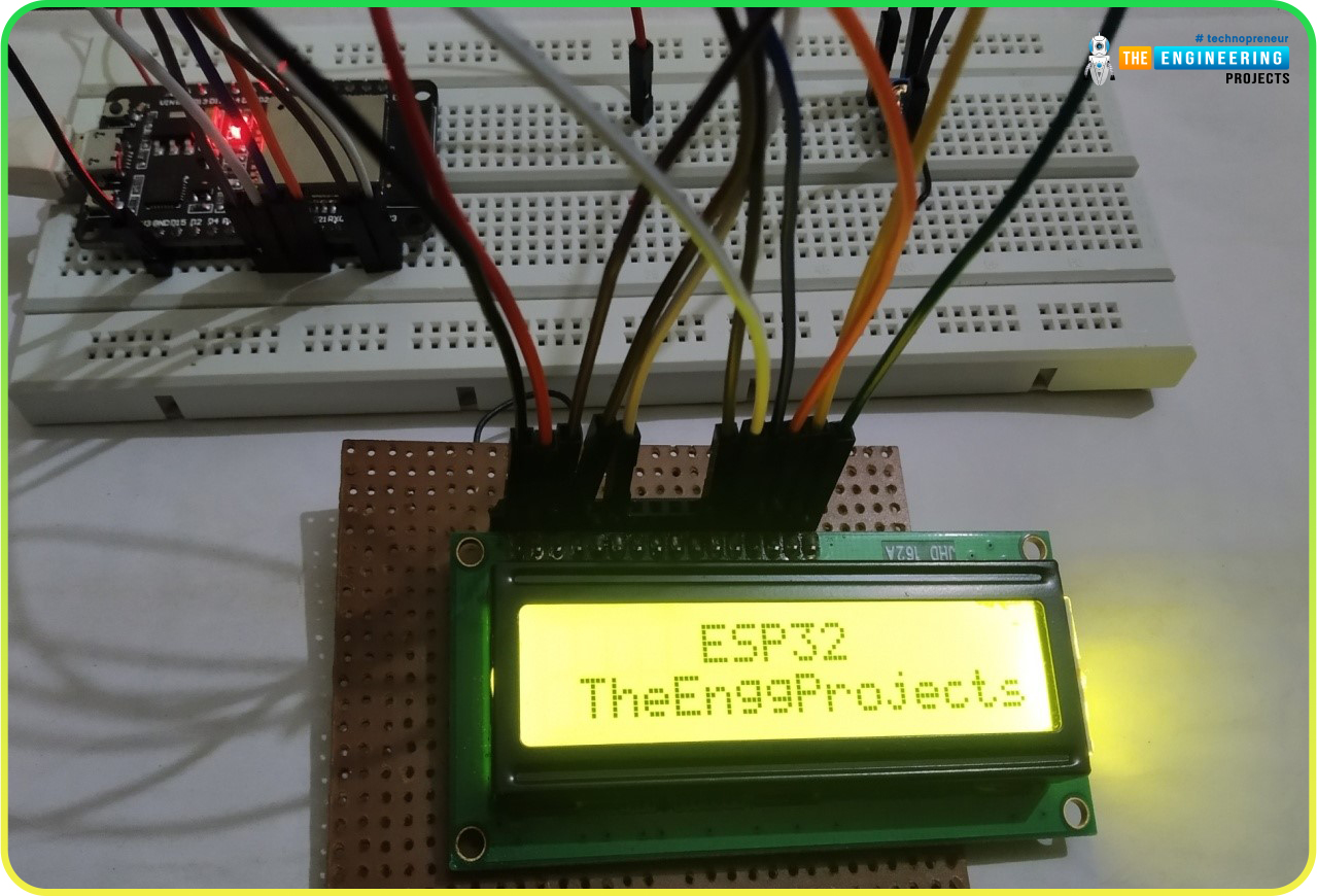
- IF everything goes fine, your text messages will get printed on the LCD at the specified locations, as shown in the below figure:

Common Errors faced while working on 16*2 LCD:
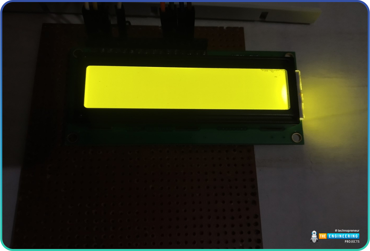
- Texts are not visible: Backlight is ON but the texts are not visible (after uploading the code) as shown in the image below. To resolve this issue:
- Check the potentiometer, whether it is connected properly or not.
- Adjust the value of potentiometer to control brightness of the display.

Fig. 6
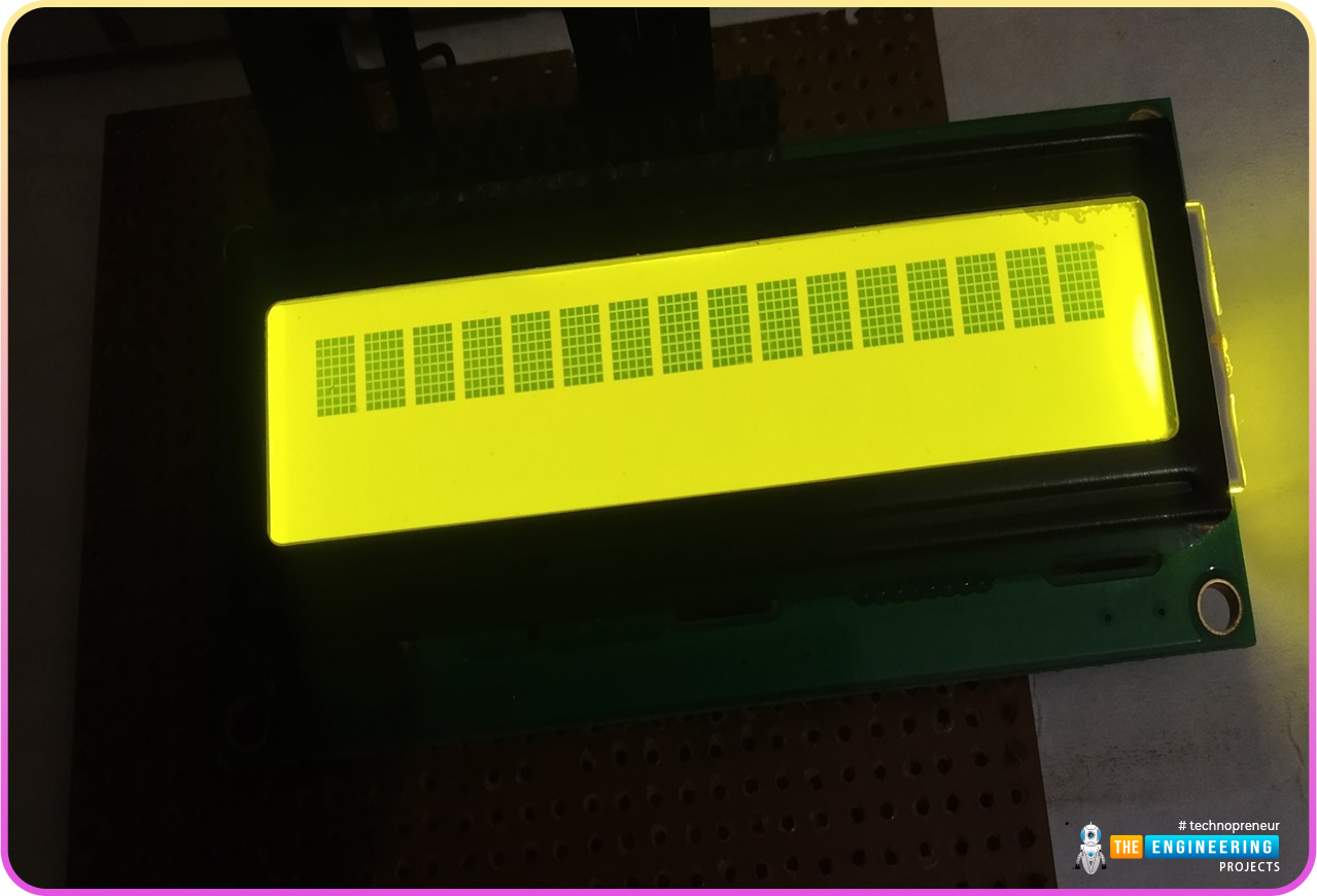
Only a single row with dark blocks is visible.
Sol. : Check the EN pin.

Fig. 7
This concludes the tutorial. We hope you found this of some help and also hope to see you soon with a new tutorial on ESP32.


 ESP32 Projects
 ahmedyasin
 1 Comments


 2.3k
2.3k
 953
953
 921
921
 2.1K
2.1K


