Hello everyone! Today I am sharing the Serial Terminal software developed in Visual Basic 2010. It provides a simple window for opening a COM port, sending text, and viewing received data in character, hexadecimal, decimal, and binary forms. We will download the original package and work through a practical communication session.
The earlier Visual Basic serial-port tutorial introduced basic transmission and reception. This terminal adds convenient display tabs and optional carriage-return and line-feed characters. Those small features are useful when a microcontroller appears to receive your command but does not respond as expected.
We will explain the original interface as it is shown, then cover connection settings, line endings, data representation, and troubleshooting. The download remains the historical software package; the discussion below does not claim that it has been rebuilt for current Windows versions or that every modern device protocol is supported.
Download the Original Serial Terminal
Use the attached download below to obtain the original Serial Terminal archive. Extract it before trying to launch the application, and keep any supplied supporting files together. The package belongs to the Visual Basic 2010 era, so its runtime requirements and behaviour should be evaluated in your intended Windows environment.
Download SoftwareA COM-port application also depends on the device or adapter appearing correctly in Windows. If you use a USB-to-UART adapter, install the appropriate driver from its manufacturer and confirm the assigned port in Device Manager. Installing a terminal cannot create a working driver for hardware that Windows does not recognize.
This article retains the original download rather than promising a new build or a verified compatibility matrix. If the application does not launch, distinguish a runtime or installation problem from a serial communication problem. There is no useful reason to change baud rates before the program itself can open normally.
Understand the Terminal Window
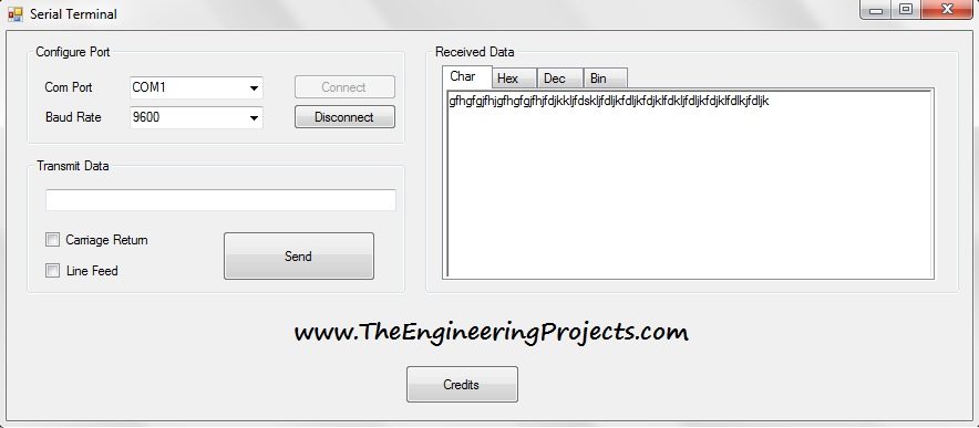
The left side of the window contains COM-port and baud-rate selection, Connect and Disconnect buttons, a transmit text field, and a Send button. Two checkboxes request a carriage return and a line feed after the outgoing text. The right side contains the received-data display and its format tabs.
| Control | Purpose | What to check |
|---|---|---|
| COM Port | Selects the Windows serial interface | Match the actual device or adapter |
| Baud Rate | Selects the serial signalling rate | Use the same rate as the connected device |
| Connect / Disconnect | Opens or closes the selected port | Release the port before another program uses it |
| Transmit Data and Send | Sends the entered text | Use a command the device actually recognizes |
| Carriage Return / Line Feed | Appends selected text terminators | Match the device's command protocol |
| Char / Hex / Dec / Bin | Changes the received-data representation | Interpret values using the correct encoding and protocol |
The screenshot does not expose separate controls for every possible serial setting. A device may also require a particular parity, data-bit count, stop-bit count, or flow-control mode. Confirm that the application's configured settings match those requirements; choosing the right baud rate alone is not sufficient.
Connect the Hardware Correctly
For a compatible logic-level UART connection, the adapter's transmit output normally connects to the device's receive input, and the device's transmit output connects to the adapter's receive input. Both sides need a common ground reference. Check the labels from the perspective of each device, because TX means “transmitted by this device”.
Do not confuse a logic-level UART adapter with an RS-232 interface. Their voltage levels and electrical conventions differ. A microcontroller pin should not be connected directly to a conventional RS-232 port merely because both are called serial. Use the appropriate transceiver or adapter for the actual electrical interface.
Likewise, check whether the microcontroller uses 3.3 V or 5 V logic and whether its inputs tolerate the adapter's output. A connector's shape does not establish its voltage level. The adapter's supply pin is also separate from the data signals; you do not need to connect it when the target is already powered appropriately.
For an initial demonstration, use a device that periodically transmits a simple ASCII line such as TEMP=25.0 followed by its documented terminator. A repeating message lets you investigate reception without simultaneously debugging a command parser on the target.
Open a Communication Session
- Connect and power the target and adapter according to their electrical requirements.
- Identify the COM port assigned by Windows.
- Close other terminal windows or development tools that may already hold that port open.
- Select the port and the target's baud rate in Serial Terminal.
- Click Connect and observe whether the port opens successfully.
- Inspect incoming text before sending a command.
- Disconnect when finished so that another application can use the port.
If the adapter is unplugged and reconnected, confirm its port assignment again. A remembered COM number is not proof that the same physical device is attached. In systems with several adapters, label them or record an identifying detail so that commands reach the intended target.
Opening a port successfully means that Windows granted access to that interface. It does not prove that the remote device has received anything. A disconnected RX wire or mismatched protocol can still leave the software apparently connected.
Choose Carriage Return and Line Feed Deliberately
Many text-command devices wait for a terminator before processing a command. Carriage return is the byte 0x0D, decimal 13. Line feed is 0x0A, decimal 10. They are different characters, even though a terminal may display their combined effect as a new line.
| Selection | Bytes after the text | Typical interpretation |
|---|---|---|
| Neither checkbox | No added terminator | Suitable only when the receiver does not require one |
| Carriage Return | 0D | Command terminated by CR |
| Line Feed | 0A | Command terminated by LF |
| Both | CR and LF appended | Use when the receiver expects the combined ending; verify order if its parser is strict |
For example, the ASCII command LED=1 contains five data bytes: 4C 45 44 3D 31. A protocol requiring CR followed by LF expects 4C 45 44 3D 31 0D 0A. A parser waiting for LF will not necessarily act when only CR arrives.
Typing the visible characters backslash and n is not generally the same as sending a line-feed byte. Unless an application explicitly interprets escape sequences, it sends the characters you typed. Use the terminal's terminator controls rather than assuming programming-language notation is understood by the transmit field.
If the device echoes your text but does not execute it, examine the terminator before changing unrelated settings. If it reports an empty command after every valid one, it may be treating CR and LF as two separate delimiters. Follow the receiver's documented framing instead of adding both checkboxes by habit.
Read the Same Data in Different Number Bases
The format tabs help you look beyond printable text. A character view is convenient for messages such as OK, while a hexadecimal view is compact for byte-oriented protocols. Decimal and binary views can help when comparing numeric values or individual bits.
Hexadecimal View
Select Hex to inspect the hexadecimal representation provided by the terminal. The original screenshot below shows that display. Hexadecimal uses base 16, so one byte can be represented with two digits from 00 through FF.

The letter A in ASCII is hexadecimal 41. That does not mean its numeric byte value is decimal 41: hexadecimal 41 equals 4 × 16 + 1 = 65. Keeping the number base explicit avoids a common source of confusion when comparing a terminal with a datasheet.
Decimal View
Select Dec to see decimal values. For the same ASCII A, the value is 65. This is useful when a protocol document lists byte values in decimal, but it should not be confused with a text string that contains decimal digits.

The text 25 consists of two ASCII bytes, decimal 50 and 53. A single binary byte with numeric value 25 is hexadecimal 19. These representations carry different data even though a person might describe both as “sending 25”.
Binary View
Select Bin to examine individual bits. The ASCII A example becomes 01000001. A byte contains eight bits, so preserve leading zeroes when comparing bit fields. Omitting them can make it harder to identify the position of a flag.

| Meaning | Hex | Decimal | Binary |
|---|---|---|---|
| ASCII A | 41 | 65 | 01000001 |
| ASCII digit 1 | 31 | 49 | 00110001 |
| Carriage return | 0D | 13 | 00001101 |
| Line feed | 0A | 10 | 00001010 |
| Numeric byte 255 | FF | 255 | 11111111 |
The examples explain byte interpretation. They do not establish that the historical application's receive path preserves every arbitrary binary byte without conversion. If you need lossless binary logging, inspect or test the byte-handling implementation rather than inferring that capability from the existence of a Hex tab.
Estimate How Long a Message Takes
Interpret Multi-Byte Values Using the Protocol
A numeric display still needs context. Suppose a device sends the two bytes 34 12 in hexadecimal. If the protocol defines a little-endian unsigned 16-bit value, the result is 0x12 × 256 + 0x34 = 4660. If it defines big-endian order, the same received bytes represent 0x34 × 256 + 0x12 = 13330. The terminal cannot infer which meaning the device intended from the bytes alone.
Signedness also matters. The byte FF is 255 when interpreted as an unsigned eight-bit number, but it represents -1 in an eight-bit two's-complement signed field. A temperature protocol might then apply a scale factor, such as tenths of a degree, after assembling and interpreting the complete numeric field.
For a status byte, individual bits may have separate meanings. If bit 2 is a ready flag, test the value with a bitwise AND against hexadecimal 04. A nonzero result means that bit is set. Comparing the entire status byte with 04 would fail whenever the ready flag and another legitimate flag were both set.
Keep the protocol description beside the captured data while debugging. Record field order, length, byte order, signedness, units, and scaling. Those definitions turn a row of hexadecimal values into an engineering measurement; changing the display tab alone does not supply them.
In a common 8N1 UART frame, each data byte uses one start bit, eight data bits, and one stop bit, giving ten transmitted bits. At 9600 baud for a binary UART signal, the nominal time per byte is 10 / 9600 = 0.0010417 s, or about 1.04 ms.
The seven-byte LED command with CR and LF therefore takes approximately 7 × 10 / 9600 = 7.29 ms on the serial line. Driver buffering, USB transfers, receiver processing, and response generation add other delays. A reply taking longer than 7.29 ms is not automatically evidence of a baud-rate problem.
The same calculation gives a theoretical data rate of about 960 bytes per second at 9600 baud with 8N1 framing. Parity, additional stop bits, flow control, and pauses can reduce the useful throughput. Avoid using the baud number directly as bytes per second.
Understand Receive Events and Message Boundaries
If you extend the program in Visual Basic, treat serial input as a stream. One receive event may contain part of a line, several lines, or a mixture of the end of one message and the start of another. Microsoft's SerialPort.DataReceived documentation explains that the event is not guaranteed for each byte and runs on a secondary thread.
Accumulate received data in a buffer and extract complete messages using the protocol's delimiter, length field, or other framing rule. Retain an incomplete trailing message for the next read. A fixed sleep after each receive event cannot reliably turn arbitrary stream fragments into complete packets.
For text, preserve the chosen encoding consistently. Microsoft's ReadExisting documentation notes that the method decodes available input as a string. For binary protocols, read and retain bytes explicitly, then build display representations from those bytes.
Post interface updates to the UI thread using the appropriate Invoke or BeginInvoke pattern. Do not disable cross-thread checking to hide an unsafe update. For high data rates, append batches of text instead of requesting a separate repaint for every byte, and limit the retained display history so the window does not grow indefinitely.
Use a Loopback Test to Separate Problems
On a suitable standalone UART adapter, a TX-to-RX loopback can help check the PC-side path. Disconnect the target first, connect the adapter's compatible transmit and receive signals together, open the port, and send a short recognizable message. Received data should correspond to the transmitted stream.
This verifies only the path included in the loop. It does not prove that the target's voltage levels, firmware parser, baud configuration, or application protocol are correct. Remove the loopback connection before reconnecting the target.
If characters appear twice, investigate local echo and remote echo separately. A terminal may display what you type locally, while a target may also transmit the same text back. Two visible copies do not necessarily mean that the UART transmitted the command twice.
Troubleshooting a Serial Session
| Symptom | Check first |
|---|---|
| Port cannot be opened | Correct COM number, adapter driver, and another application holding the port |
| Connected but no received data | Target power, TX-to-RX wiring, ground, and whether the target actually transmits |
| Unreadable characters | Baud rate, framing, electrical levels, and text encoding |
| Command is ignored | Exact command spelling, required terminator, and device mode |
| Extra blank lines | CR/LF handling and whether terminators are being added twice |
| Receive display slows over time | Unbounded text history or overly frequent UI updates |
| Communication stops after unplugging USB | Close the failed session and reopen the currently assigned port |
Change one setting at a time and record the result. A known test message is more useful than random typing because you can predict its exact bytes. If a protocol includes a checksum, verify the checksum over the actual payload bytes rather than the visible hexadecimal characters used to describe them.
Review of the Original Serial Terminal
The terminal's useful features are its straightforward connection controls, optional line endings, and multiple received-data views. It is a practical introduction to observing serial traffic and comparing representations. Its historical interface should not be mistaken for a full protocol analyzer or a guarantee of support for every binary framing scheme.
When extending it, prioritize reliable byte handling, clear connection errors, bounded logging, and explicit communication settings. Those improvements matter more than adding display tabs that show attractive numbers but obscure how the underlying data was received.
Frequently Asked Questions
Does choosing Hex change what the device transmitted?
No. A display format changes how data is presented. It does not retroactively alter the signal or the receiver's protocol.
Can I send a binary byte by typing its hex digits?
Not unless the transmit field explicitly supports hexadecimal input. Typing FF into a text field usually sends two character bytes, not one byte with value 255.
Should I enable both CR and LF for every device?
No. Use the terminator required by that device. An extra character can create an empty command or an invalid packet.
Can two programs use the same COM port simultaneously?
Ordinary Windows serial-port use generally requires one program to own the port. Disconnect one application before opening the port in another.
Is this a new release of the software?
No. The attached archive is the original package, accompanied by an updated explanation of its interface and the engineering principles needed to use serial communication effectively.