Hi readers! Hopefully, you are doing well and exploring something fascinating and advanced. Imagine that particles can pass through walls but not by breaking them down? Yes, it is possible. Today, we will study Quantum Tunneling.
Quantum tunneling may be one of the strangest and illogical concepts of quantum mechanics. Quantum Tunneling proves the phenomenon of particles like electrons, protons, or even whole atoms percolating through the energy barrier of potential energy, although they do not appear to have sufficient potential to slide over it. The classical physics version of this ball at this point would merely reverse.
Nevertheless, in the quantum realm of things, particles now act like waves, and waves can pass through and even over barriers with some nonzero probability of the pa ...
Till now, we have read about the basic concepts and functions in the signal and system, but let’s have something that is more practical and practice each and every topic thoroughly because if you have the understanding at each point, transforming will become an interesting game for you.Keep in mind, that transforms are an important topic in signal processing, but they were traditionally taught in the same way they were discovered: through calculus. This approach, however, does not reveal the true purpose of the transforms or why they are desirable. Well, let’s check the topics that we are going to learn about today:
What are transforms?
Which common transforms are used in signals and systems?
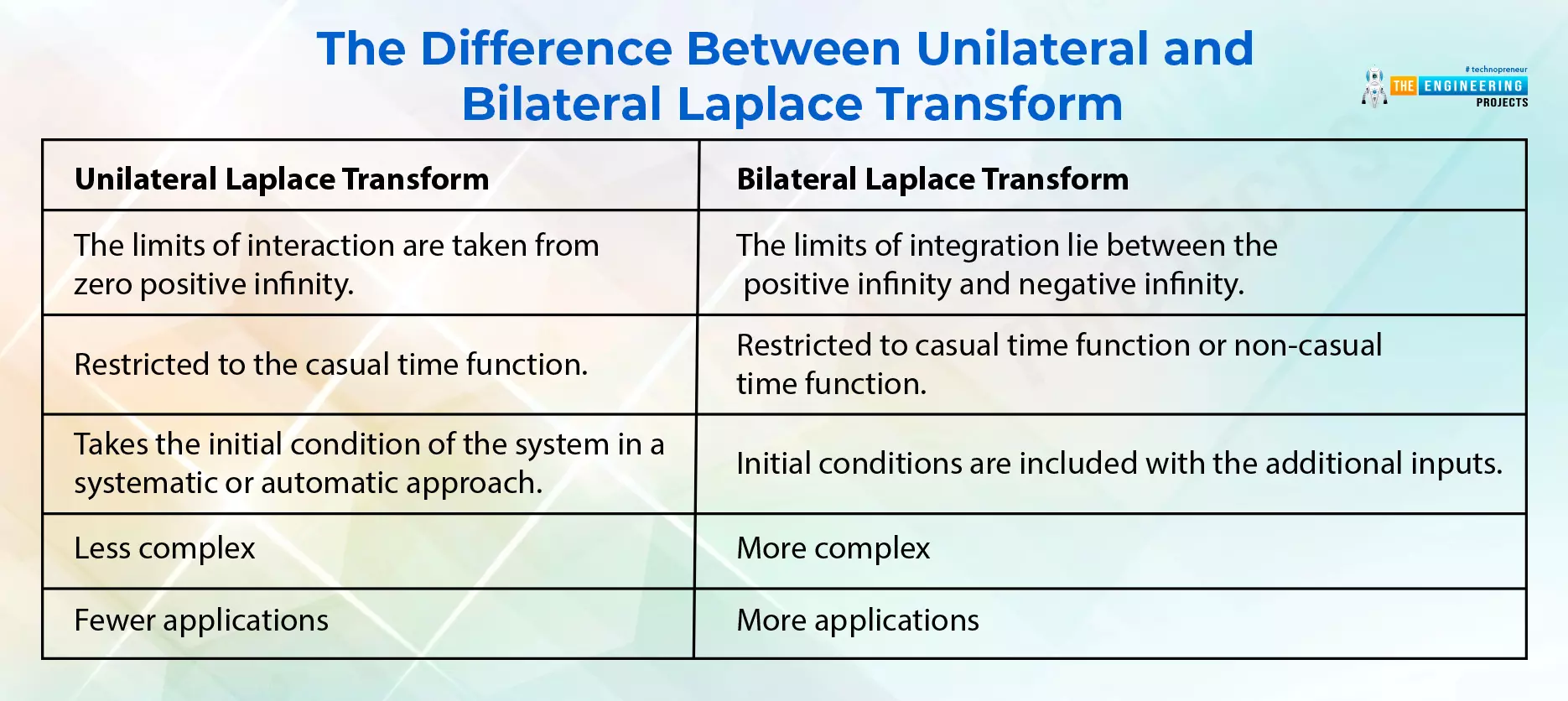
What is the Laplace transform?
How can you implement the Laplace transform in MATLAB?
What ar ...
Hey geeks, welcome to the next article of this series on signals and systems. In the previous lecture, we saw the basic types of convolution and learned about convolution in MATLAB. This time, we are going to enhance some concepts about it by learning about the properties of convolution and by adding some important pieces of information about the same topic. Have a look at today’s concepts:
What are some basic properties of convolution?
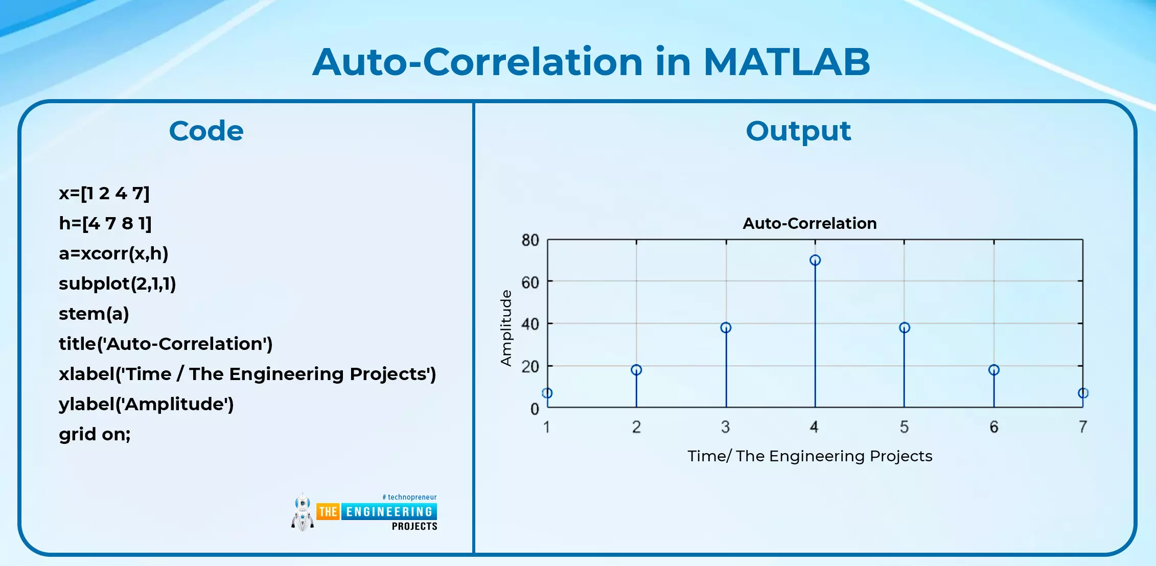
What is the correlation?
Discuss some types of correlation and their implementation in MATLAB.
What is the difference between convolution and correlation?
How convolution is used in different areas of science and how different departments are using this technique to control the parameters efficiently.
The Properties of Convolution
Once you ...
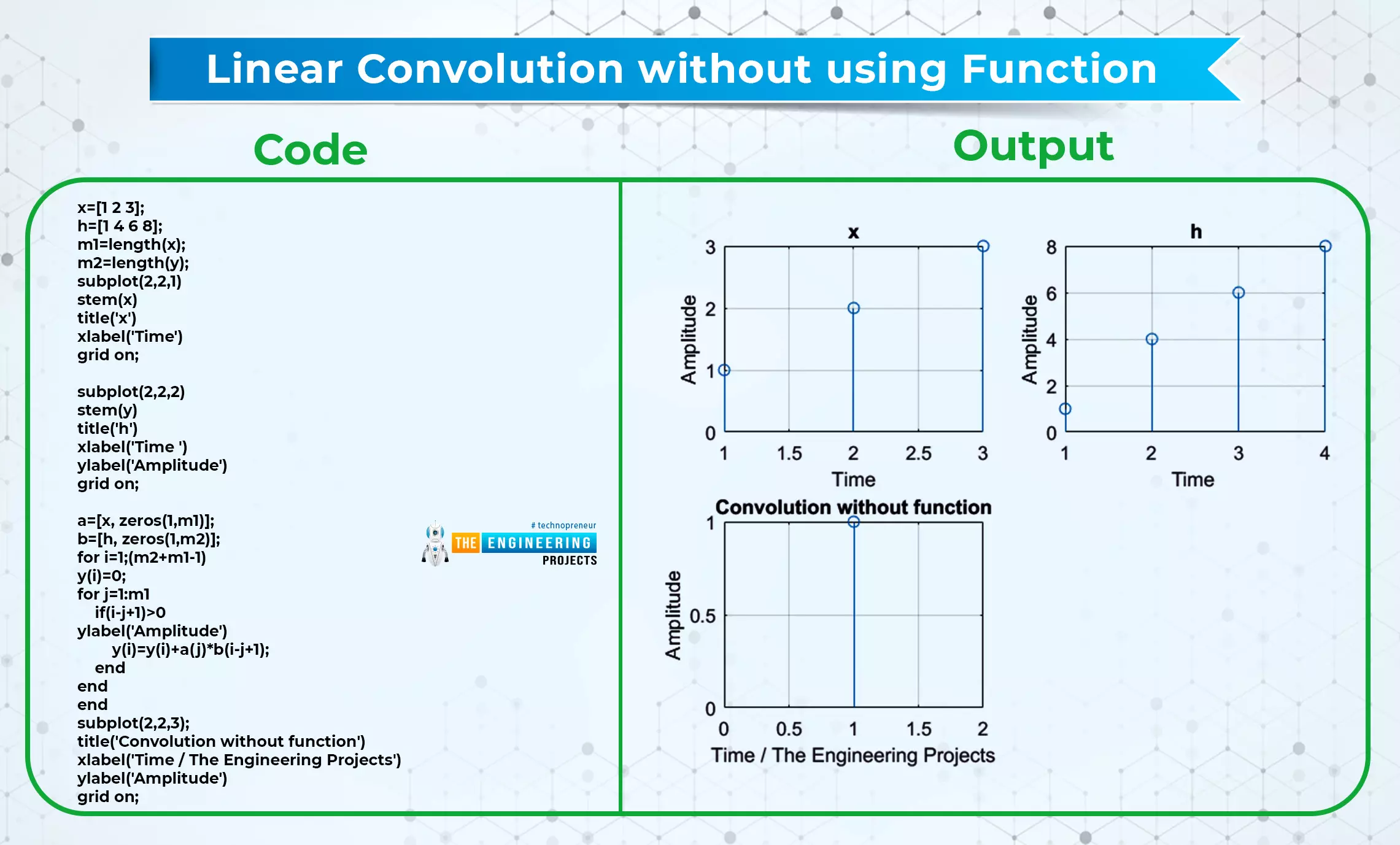
Hey pupils, Welcome to another lecture of this series on signals and systems, and this is the time to learn an interesting topic in which you are going to learn about the convolution of the signals. In the previous sessions, we have learned basic operations on the signals, and this time, you are going to know the convolution of the signals and different criteria that are related to this topic. Have a quick view of the concepts that will be clarified in this lecture: What is convolution? What are some basic types of convolution? How can you define the properties of linear convolution? How can you implement convolution in MATLAB using function and without function? What is the difference between linear and circular convolution? What is the convolution of signals? Convolution is ...
Hello Pupils, We are learning about signals and systems, and till now we have learned some basic information regarding signals, but we know a little about systems till now. We have learned about the system in our previous lectures. To have a clear concept, we have arranged this tutorial in which we are studying the systems and their classification. Have a quick glance at today’s topics:
What is a system?
What are the various types of systems?
What is the principle of homogeneity?
What is the principle of superposition?
How can we compare each type while keeping their differences in mind?
To keep things simple, we’ll also have examples of some of these signals. Yet, the first thing that we are going to do is to revise the basic definition of the system so that we may move forward. ...
Hey peeps welcome to The Engineering Projects. This is the third lecture of this series, and till now, we have discussed the introduction to the signal and system, and in the previous lecture, we learned about the classification of signals and the difference between some of them.
In the present day, you are going to learn the basic operations of signals, and it is amazing to note how you can play with these signals. The best thing about this series is that you are going to see every step with the help of MATLAB. Let’s have a quick glance at today’s topic, and after that, we will go through a detailed explanation.
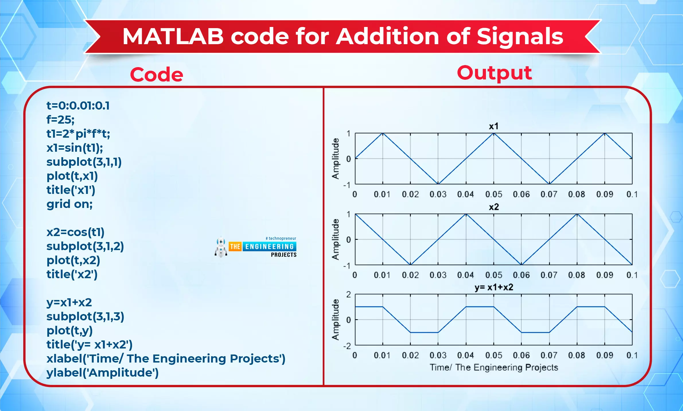
Addition of Two Signals
Subtraction of Two Signals
Multiplication of Two Signals
Time Scaling (Compression and Expansion)
Time Shifting (Addition and subtraction)
R ...
Introduction
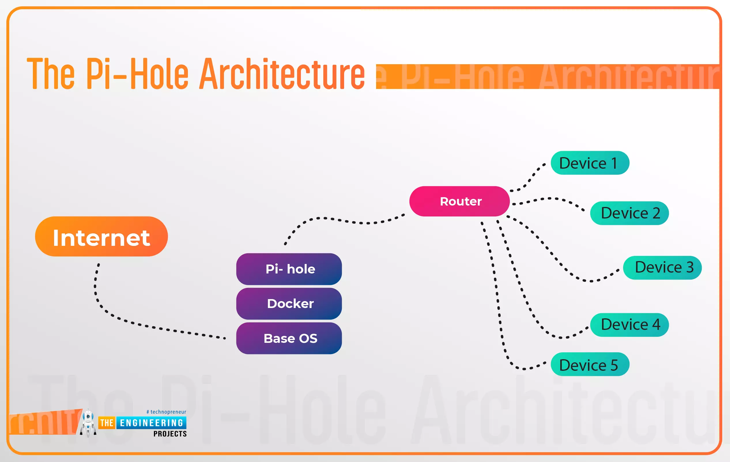
Thank you for joining us for yet another session of this series on Raspberry Pi programming. In the preceding tutorial, a facial recognition system on a Raspberry Pi 4 was used to develop a smart security system. We also learned how to create a dataset using two Python scripts to train and analyze a series of photographs of a certain person. This tutorial will teach you how to install pi-hole on a Raspberry Pi 4 and use it to block advertisements from anywhere. This is a great initiative for folks who are tired of annoying pop-up adverts while browsing. First, we'll learn how to set up the pi-hole without the need for an environment, then we'll use Docker to install pi-hole, and ultimately we'll see how we can access it from anywhere.
Prerequisites
A minimum of 512MB ...
Hello! Welcome to the engineering projects. This is the second part of the signal and system series in which we will discuss some essential classifications of simple signals. In the previous session, we discussed the introduction of signals and systems and also ran some simple codes on MATLAB for the implementation of some simple codes.
In this session, we are discussing some essential types of signals, and the best part is that we will implement all the signals in MATLAB for the best understanding. Here is a quick glance at all the topics that we will discuss today:
Continuous-Time Signals
Discrete-Time Signals
Periodic Signals
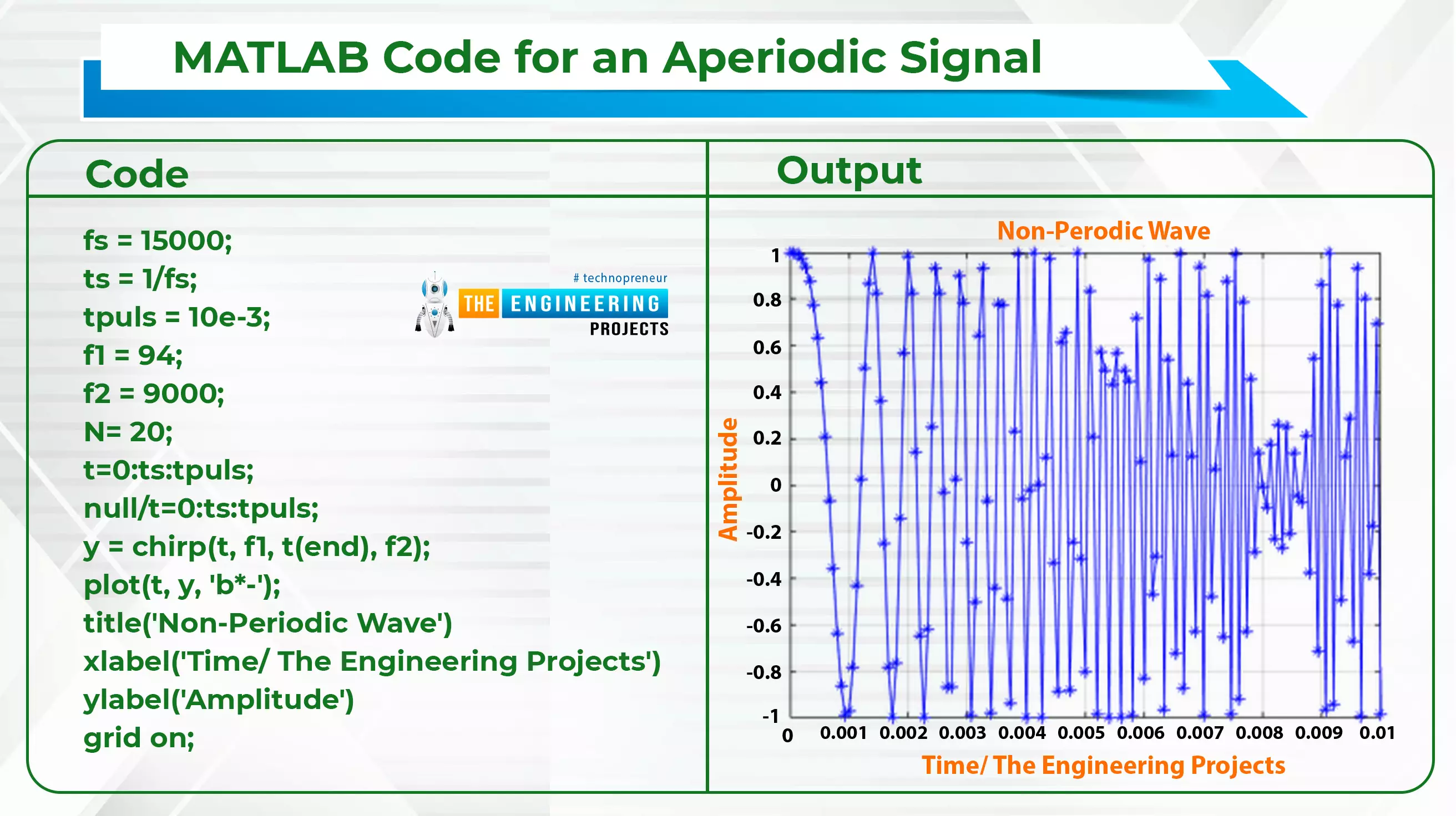
Aperiodic Signals
Even Signals
Odd Signals
Deterministic Signals
Non-Deterministic Signals
Energy Signals
Power Signals
What are functions?
Some ...
Signal and systems is an essential subject in electrical engineering and it is not just limited to this particular branch of engineering but students of many other branches such as computer engineering learn and practice this subject in their field. For design and analysis, all engineering topics make use of models of real-world things. Signals and systems provide you with the ability to take on the challenge of getting the job done.
Signal and system are two terms that, when studied and performed together, form a fantastic visualization of different phenomena. Have a look at these two terms.
What is the signal?
A signal is defined as the description of comparing two parameters and how they vary with each other. Signals are the representation of some sort of information with the help of ...
You can use a multimeter to figure out what's wrong with the electrical system in your car. Most of the time, if you check for voltage and continuity, you can figure out where the problem is coming from. This article will show you how to use a multimeter on a car.
First, make sure the multimeter isn't on. Then connect the positive lead to the positive terminal on the battery. Connect the negative lead to a metal piece on the frame of the car. The last step is to turn on the multimeter and read the results. If it says 0 volts, it means that no electricity is moving through the circuit. If the voltage is 12 volts or more, then there is a current in the circuit.
A multimeter can be helpful if you can't figure out what's wrong with your car's electrics. You should be able to fix many c ...