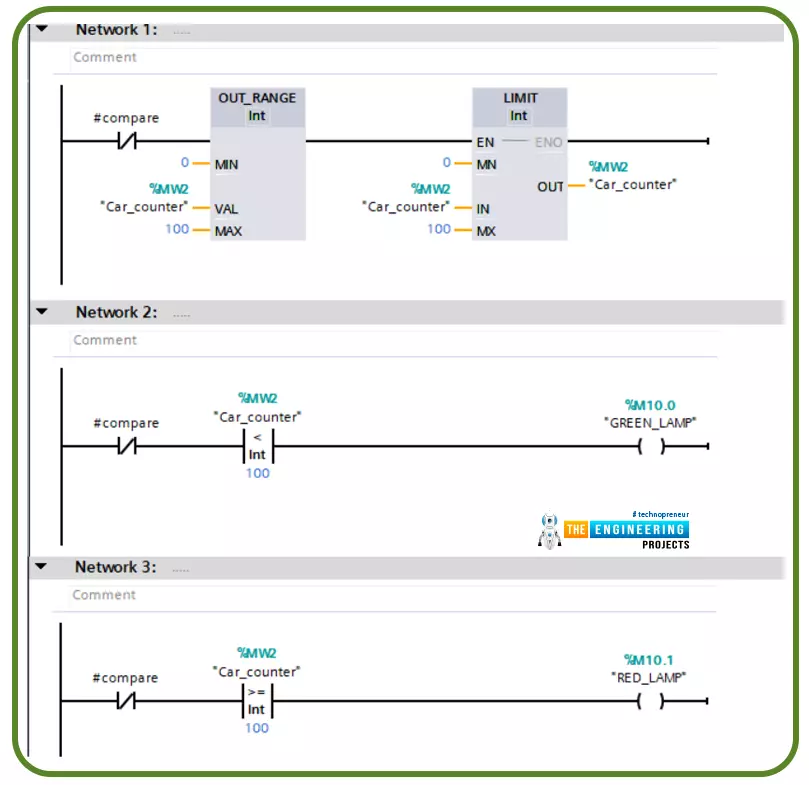
Hi friends. Today we are going to go through one of the most commonly used topics in writing ladder logic programming which is using comparator operations. This includes the logical and mathematical comparison between variables to decide where the logic goes.
There are many comparator operations like equal (==), not equal (<>), less than (<), greater than (>), less than or equal (<=), greater than or equal (>=). All these comparator operations might be used in different logic scenarios while writing a ladder logic program. In this tutorial, we are going to go over each operator showing the input operators and output as well. In addition, we will practice some examples with the simulator to familiarize how to use them flexibly whi ...
Hello friends, I hope you all are doing great. This is the 7th lesson of our Python tutorial. We were introduced to Python numbers in the previous chapter and learned how they are utilized with expressions, so we have a good understanding of math operations.
We'll go over a couple more arithmetic functions and complex numbers in this lesson. I will try my best to keep it simple. Let's get started!
Python round function
You can work with numbers in Python using a few built-in functions. Three of the most common will be discussed in this section:
Rounding to a specific number of decimal places can be done with round().
abs(), which returns a number's absolute value.
pow(), which raises a number to a ...
Welcome to chapter 6 of our python course. Previously, we introduced integers and saw how they may be combined with strings and stored in variables. Today, we'll take a closer look at the python number types and how they're stored in variables to see what actions are possible.
What you'll learn in this tutorial is how to:
Add, subtract, multiply, and divide numbers.
Work with modular.
Use exponents.
Use expressions.
Use a predetermined number of decimal places to round numbers
Use strings to format and show numeric data.
With this in mind, let`s start.
How are integers created?
Integers can be created by simply inputting a number. For example, the tutorial variable is assigned the integer 6 in the following way:
>>>Tutori ...
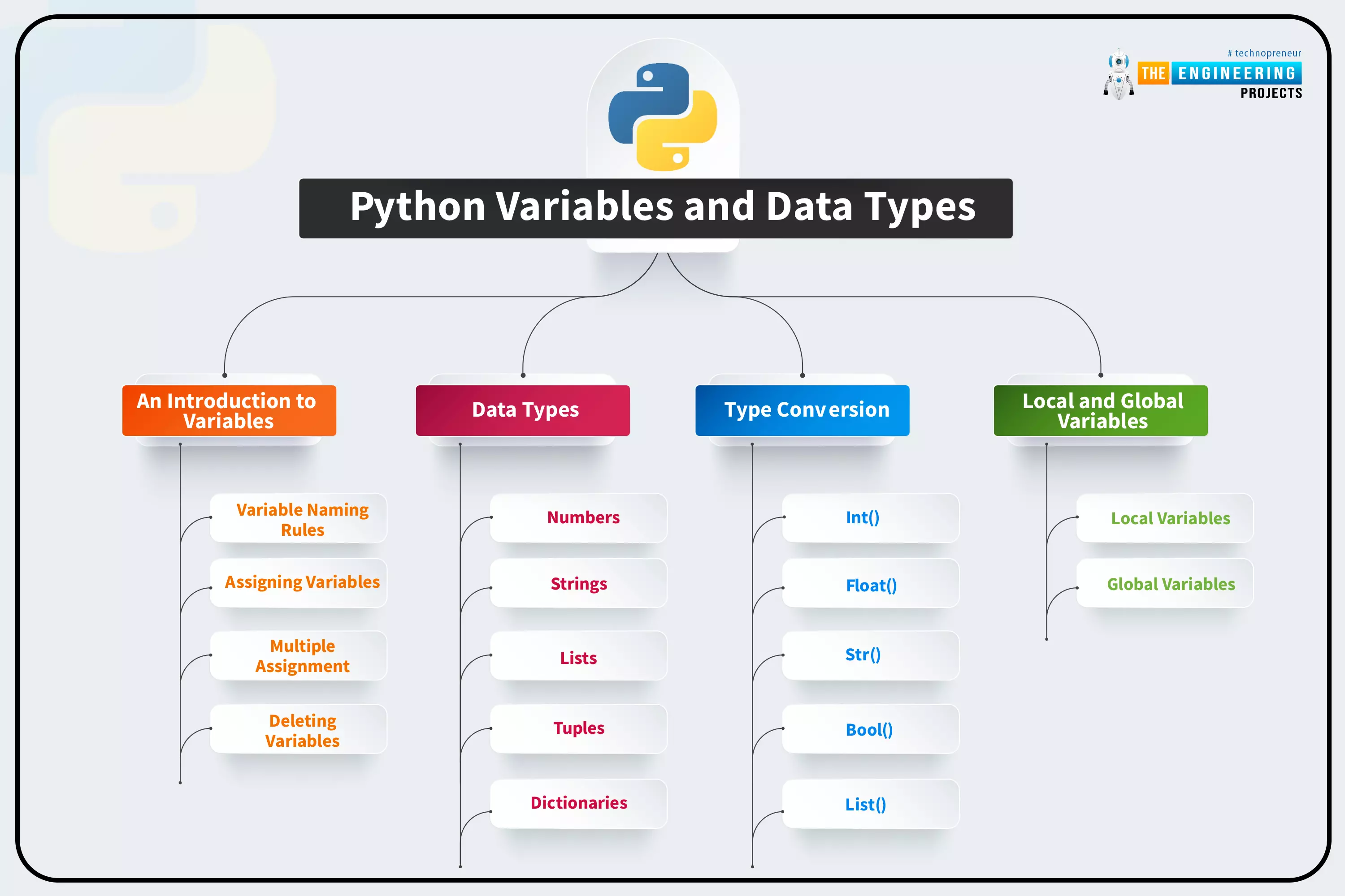
Welcome back! This is the fifth lesson in our Python programming course. In the last chapter, we discussed how string data types are used in Python. In this tutorial, we’re going to discuss variables in python and the rules for naming them in Python. In addition, you'll learn the fundamentals of working with numbers and strings.
What are variables?
All programming languages use variables as a fundamental building block of their language. It is the allocation of memory that is dedicated to data storage and manipulation. Variables are program elements that keep track of data. The following is an example of a variable.
x = 100
It's called x in the diagram below, and it has a value of 100 in it. In this case, the variable name is x, and the data it c ...
Hello everyone and welcome to this article. Previously we have been discussing different types of PCB boards and for sure we have not exhausted everything. Today we are going to focus on a very important aspect of the PCB design which is the thermal characteristics of the PCB's working environment. Up to this moment, we have interacted with boards that work best in normal working conditions. But remember there are some working conditions, that have very harsh environment such as high temperatures. Let us take for example temperature in boilers or even electric heaters. Do you think normal FR-4 boards can survive in such temperatures? Don’t you think they will melt off if exposed to high thermal radiation? Your guess is as good as mine. For us to h ...
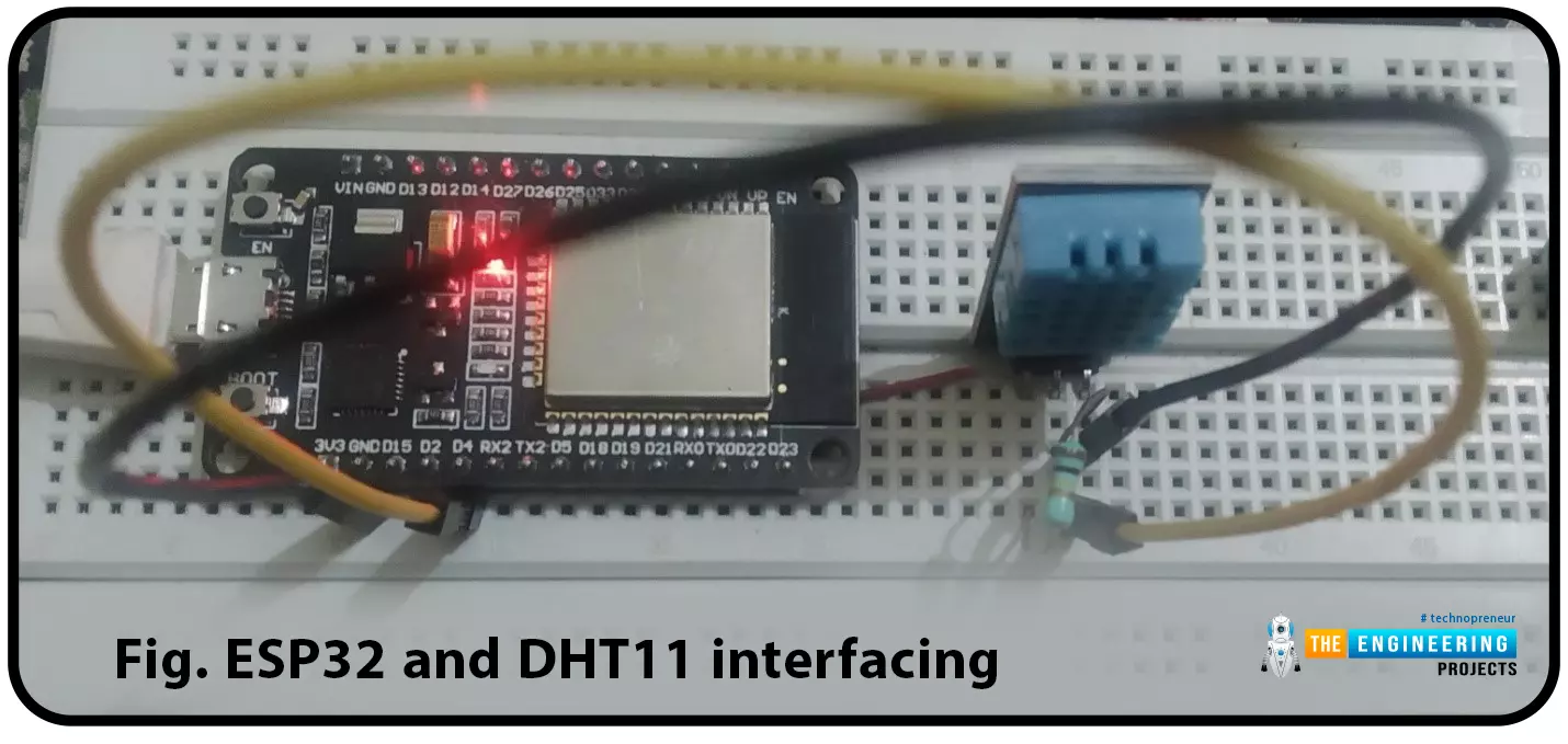
ESP32 module comes with multiple inbuilt features and peripheral interfacing capability is one of those features. ESP32 module also consists of an inbuilt temperature sensor, but that can only measure the temperature of the ESP32 core not the temperature of the surrounding environment. So it is required to use a peripheral sensor to measure the temperature of the surrounding environment like home, garden, office etc.
Hello readers. I hope you all are doing great. In this tutorial, we will learn how to interface DHT11 (temperature and humidity sensor) with the ESP32. Later in this tutorial, we will discuss how to share the sensor readings obtained from the DHT11 sensor to a web server.
Before moving towards the interfacing and programming part, let’s have a short introduction to the DHT11 ...
Public cloud computing systems enable businesses to complement their data centers with worldwide servers that can scale processing capabilities up and down as required. In terms of value and security, hybrid public-private clouds are unparalleled.
However, real-time AI applications demand substantial local processing capacity, frequently in areas distant from centralized cloud servers. speedpak tracking is among the services including AI for the safety of your goods and parcels.
Moreover, some workloads demand low latency or data residency and must stay on-premises or specified locations.
That is why many businesses use edge computing to implement AI applications.
Instead of storing data in a centralized cloud, edge computing saves data locally in an edge device. Moreover, the gadget may ...
The IoT is the interconnection of physical objects or devices with sensors and software accessing capabilities to communicate data or information over the internet.
To build an IoT network, we need an interface medium that can fetch, control, and communicate data between sender and receiver electronics devices or servers.
Espressif Systems created the ESP32 Wi-Fi chip series. The ESP32 module is equipped with a 32-bit Tensilica microcontroller, 2.4GHz Wi-Fi connectivity, an antenna, memory, and power management modules, and much more. All of these built-in features of this ESP32 module make it ideal for IoT applications.
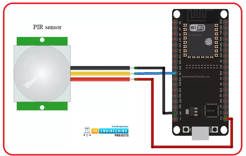
Hello readers, I hope you all are doing great. In this tutorial, we will learn another application of ESP32 in the field of IoT (Internet of Things). We are using a PIR s ...
Hi Friends! Hope you’re well today. In this post, I’ll walk you through What is Edge Computing?
Edge computing is the extension of cloud computing. Cloud computing is used for data storage, data management, and data processing. While Edge Computing does serve the same purpose with one difference: edge processing is carried out near the edge of the network which means data is processed near the location where it’s produced instead of relying on the remote location of the cloud server.
Confused?
Don’t be.
We’ll touch on this further in this article.
Curious to know more about what is edge computing, the difference between edge computing and cloud computing, benefits, and applications?
Keep reading.
What is Edge Computing?
Edge computing is the process where data is processed near or at th ...
Hi guys! Hope you’re well today. In this post today, I’ll cover What is Industrial IoT (Internet of Things?)
IIoT is now a talk of mainstream conversation. This term has blown up in the past couple of years. Before we move further to describe IIoT, it is evident that industries are no longer dependent on the traditional production processes that happened to be costly and guaranteed no optimal results. Now companies are willing to incorporate automation in manufacturing and production processes. Smart systems, no doubt, are dangerous for the traditional labor workforce, but on the other hand, they create more opportunities for the people equipped with the latest business trends.
Curious to know more about Industrial IoT, how does it work, the difference between IoT and IIoT, examples of II ...