Introduction to TCS3200
Hello friends, I hope you all are doing great. In today's tutorial, we are gonna have a look at a detailed
Introduction to TCS3200. TCS3200 is a color-detecting sensor, it consists of TAOS TCS3200 RGB sensor chip and four white LEDs. It is used to detect visible color in a measurable range. This sensor has an array of a photodetector diode, some diodes are equipped with different color filters i.e. red, blue or green color and some diodes do not have any filter.
TCS3200 has different applications such as test strip reading, sorting by color and ambient light sensing. In today's post, we will have a look at its working, protocol, pinout, specification, etc. I will also share some links where I have interfaced it with other microcontrollers. If you have any questions about it ask in the comments I will resolve your problems.
So, let's get started with a basic Introduction to TCS3200.
Introduction to TCS3200
- TCS3200 is a color-detecting sensor, it consists of TAOS TCS3200 RGB sensor chip and four white LEDs. It is used to detect visible color in a measurable range.
- It is a programmable sensor and color light-to-frequency converter. The board of this sensor is a monolithic integrated circuit that consists of a configurable silicon photodiode and a current-to-frequency converter.
- The output of this sensor is a square wave (50% duty cycle), the frequency of output depends on the intensity of light (irradiance).
- The output frequency of this sensor can be scaled by two input control pinouts. Due to its digital input and digital output, it can easily be interfaced with other microcontrollers.
- The light-to-frequency converter of this sensor reads the 8 x 8 array of photodiodes. In this array of photodiodes, 16 photodiodes have green filters, 16 have blue filters, 16 have red filters and sixteen photodiodes have no filters.
- To minimize, the effect of non-uniformity of incident radiation all photodiodes are interdigitated. The same colored diodes are connected in parallel. We can use pin S2 and S3 to check which group of photo diodes is active.
- The dimensions of photodiodes are 110um x 110um.
- The operating temperature of this sensor is -40°C to +85°C and it is available in 8-SOIC packages.
- This sensor is mostly used in RGB-led industrial control projects and medical diagnostic types of equipment.
Now, we discuss TCS3200 pinouts with a detailed description.
TCS3200 Pinout & Description
- There are main eight pinouts of TCS3200 which are described below.
| Pin# |
Type |
Parameters |
| Pin#4 |
GND |
This pin is the power supply ground. All voltages are reference to the ground. |
| Pin#5 |
VCC |
It is a supply voltage. |
| Pin#3 |
OE |
Enable for FO (Active low). |
| Pin#6 |
OUT |
This pin is for output frequency (fo). |
| Pin#1,2 |
S0, S1 |
Using these pins we can Select lines for output frequency scaling. |
| Pin#7,8 |
S2, S3 |
Using these pins we can Select lines for photodiode type. |
Now, we discuss the specifications of TCS3200, which are described below.
Features of TCS3200
- These are the main features of TCS3200.
- Its operating voltage is 2.7v to 5.5v.
- Its operating current is 2 mA at 5 V.
- Its interface is digital TTL.
- It can easily convert light intensity to frequency with high resolution.
- There is no need for ADC.
- It operating temperature is -40 C to 85 C.
- It has a power down attribute.
- Its dimensions are 28.4x28.4mm(1.12x1.12").
- It is available in a 5mm x 6.2mm SOIC (D) package.
- It is programmable.
- It supports LED lamp light supplement control.
Working of TCS3200
- As we have already seen that TCS3200 has an 8 x 8 array of photodiodes, which are used for color sensing.
- When light falls on these photodiodes, then these light signals are converted into square waves and the frequency of these square waves is dependent on the intensity of falling light.
- After getting results from light to frequency converter, which is a square wave, we can simply fed them to any microcontroller like Arduino, PIC Microcontroller or Atmel etc and detect the color of falling light.
- If we observe a given diagram we can easily understand how the sensor can detect various colors.
- As we earlier discussed that photodiodes of the sensor have three different filters which are red, green, and blue while one group of photodiodes have no filter.
- All sixteen photodiodes of a sensor are connected in parallel, by using two pins S2 and S3 we can select which pin we have to use for color reading.
- Let's suppose we have to detect red color, we just have to use sixteen red filter photodiodes by setting two pin S2 and S3 to low logic level according to a given table.
- TCS3200 also has two more pins used for controlling purposes, and are named as S0, and S1.
- These two switches are used for tuning the frequency of square wave. We can set the output frequency to either 2%, 20% or 100%. These are builtin frequency values.
- This function tells us that we can optimize the sensor output for various counters and microcontrollers.
Applications of TCS3200
- These are some applications of TCS3200.
- As we know this is a color light sensor, so we use it in color detecting projects, otherwise we have to use MATLAB for color detection, which will need laptop (not a good option).
- TCS3200 is used for object sorting based on color.test strip reading,
- We can also sense ambient light using this sensor.
- We can also read color codes on LED strips.
So, friends that were all about TCS3200 If you have any questions about it please ask in comments. Thanks for reading. Take care until the next tutorial.
Introduction to MSP430
Hello friends, I hope you all are doing great. In today's tutorial, we are gonna have a look at a detailed
Introduction to MSP430. MSP430 is a microcontroller portfolio that offers different varieties of sixteen-bit
Microcontrollers. These microcontrollers are integrated with ultra-low power and digital and analog peripherals devices for sensing and measurement applications. MSP430 microcontrollers with non-volatile FRAM (ferroelectric random access memory) provide the lowest stand-by power (350nA with RTC), 100 µA/MHz active power and have the capability to recover system state after sudden power failures.
MSP430 is used in different applications such as sensor systems which receive analog signals and convert them into digital values and after processing send these values to host systems. In today's post, we will have a look at its introduction, working, protocol, features, applications, etc. I will also share some links where I have interfaced it with other microcontrollers. If you have any questions please ask in the comments, and I will resolve your problems.
So, let's get started with a basic Introduction to MSP430.
Introduction to MSP430
- MSP430 is a microcontroller portfolio that offers different varieties of sixteen-bit Microcontrollers. These microcontrollers are integrated with ultra-low power and digital and analog peripherals devices for sensing and measurement applications.
- This module consists of five low-power modes that increase battery life in portable measurement applications.
- MSP430 has a feature of 16-bit registers, sixteen-bit RISC Cpu and constant generators which provides maximum code efficiency.
- The digitally controlled oscillator (DCO) of this module converts low power modes to active mode in less than 6µs.
- The MSP430x11x series is an ultra-low power signal microcontrollers that consist of a 16-bit timer and fourteen input and output pinouts.
- MSP microcontrollers give ideas and enable designers to produce such high-performance applications, which support the industry's lowest stand-by power, analog and digital devices suitable for sensing and measurement applications, and also support 20+ wired and wireless connectivity applications.
- The main applications that it provides are sensor systems that receive analog signals and convert them into digital values, and after processing this data sends to host modules. Another area of application is RF front-end sensor.
Now, we discuss its pinouts.
Pinout of MSP430
These are the main pinouts of MSP430 which are described below.
| Pin# |
Type |
Parameters |
| Pin#13 |
P1.0/TACLK |
It is general-purpose digital I/O pin / Timer_A, clock signal TACLK input. |
| Pin#14 |
P1.1/TA0 |
It is general-purpose digital I/O pin/Timer_A, Capture: CCI0A input, Compare: Out0 output. |
| Pin#15 |
P1.2/TA1 |
It is general-purpose digital I/O pin/Timer_A, Capture: CCI1A input, Compare: Out1 output. |
| Pin#16 |
P1.3/TA2 |
It is general-purpose digital I/O pin/Timer_A, Capture: CCI2A input, Compare: Out2 output. |
| Pin#17 |
P1.4/SMCLK/TCK |
It is general-purpose digital I/O pin/SMCLK signal output/Test clock, an input terminal for device programming and test. |
| Pin#18 |
P1.5/TA0/TMS |
It is general-purpose digital I/O pin/Timer_A, Compare: Out0 output/test mode select, an input terminal for
device programming and test. |
| Pin#19 |
P1.6/TA1/TDI |
It is general-purpose digital I/O pin/Timer_A, Compare: Out1 output/test data input terminal. |
| Pin#20 |
P1.7/TA2/TDO/TDI |
It is general-purpose digital I/O pin/Timer_A, Compare: Out2 output/test data output terminal or data input
during programming. |
| Pin#8 |
P2.0/ACLK |
It is general-purpose digital I/O pin/ACLK output. |
| Pin#9 |
P2.1/INCLK |
It is general-purpose digital I/O pin/Timer_A, a clock signal at INCLK. |
| Pin#10 |
P2.2/TA0 |
It is general-purpose digital I/O pin/Timer_A, Capture: CCI0B input, Compare: Out0 output. |
| Pin#11 |
P2.3/TA1 |
It is general-purpose digital I/O pin/Timer_A, Capture: CCI1B input, Compare: Out1 output. |
| Pin#12 |
P2.4/TA2 |
It is general-purpose digital I/O pin/Timer_A, Compare Out2 output. |
| Pin#3 |
P2.5/ROSC |
It is general-purpose digital I/O pin/Input for an external resistor that defines the DCO nominal frequency. |
| Pin#7 |
RST/NMI |
It is Reset or nonmaskable interrupt input. |
| Pin#1 |
TEST/VPP |
It is selected test mode for JTAG pins on Port1/programming voltage input during EPROM programming. |
| Pin#2 |
VCC |
It is a Supply voltage. |
| Pin#4 |
VSS |
It is Ground reference. |
| Pin#6 |
XIN |
It is an Input terminal of the crystal oscillator. |
| Pin#5 |
XOUT/TCLK |
The output terminal of a crystal oscillator or test clock input. |
Now, we discuss the features of MCP430.
Features of MSP430
- These are the main features of MCP430, Lets's discuss them with detailed.
- It is available in a 20 pin plastic small outline widebody package.
- Its operating voltage range is 2.5v to 5.5 v.
- Its active mode is 330 µA at 1 MHz, 3 V.
- Its stands by mode are 1.5 µA.
- It's off mode (Ram Retention) is 0.1 µA.
- This module is available in 16-bit architecture, 200ns instruction cycle time.
- This module consists of various internal resistors, single external resistor,32 kHz crystal, high frequency, resonator and external clock source.
- It has a 16-bit timer with a three capture/compare registers.
- In this module, programme protection is done by a security fuse.
- It has serial onboard programming.
- This module has 16 kb flash, 512 B RAM, 8ch 10-bit ADC, two 16-bit timer
MSP340 Interfacing with RFID
- In the next coming lines, we will discuss MSP430 interfacing with RFID, first of all, we discuss components required for this circuit.
- Circuit Components
- MSP430 Launchpad.
- EM-18 (RFID reader module).
- 16*2 LCD.
- Potentiometer.
- Breadboard.
- Jumper wires.
- In this circuit diagram, we are going to use UART hardware of MSP430, So you should put RXD and TXD jumpers on HM UART mode. After this connect the Tx of EM-18 to RXD (P1.1) of MSP430.
- In this project, we are going to use serial communication of data transfer. RFID also has another mode than serial mode but we are using RS232 communication mode. The RS232 pin of RFID the module connects with RXD pin of MSP430.
- To connect the RFID reader with MSP430 we have to enable the serial communication in MSP430.
- We can initialize serial protocol in MSP430 by using a simple command Serial.begin(9600), where 9600 is the baud rate.
- Now in order to read the incoming Serial data, we need to use value=Serial.read().
- We can see in the given diagram that for communication by RFID use BAUD rate of 9600 bits per seconds. For MSP430 to create baud rate equal to the RFID baud rate to start communication, we use the command of "Serial.begin(9600);". 9600 is a baud rate which can change.
-
After setting of baud rate, MSP430 is ready to receive data. This data can be received by command “data = Serial.read();”. By this way, serial data is taken in 'data ' named Integer.
-
When we take a card near the reader, the reader reads data and forward it to MSP430, MSP430 after getting data show on LCD. So we will have an ID of a card on LCD.
Applications of MSP430
- These are some applications of MSP430.
- It is used for Factory Control & Automation Applications
- It is used in Building & Home Automation Applications.
- It is used in Grid Infrastructure & Metering Applications.
- It is used in Portable Test & Measurement Equipment.
- It is used in Health, Medical & Fitness Applications
- It also used in Consumer Electronics.
So, friends, that's was all about MSP430 If you have any question about it please ask I comments I will resolve your problems. Take care until next post.
Introduction to BD139
Hello friends, I hope you all are doing great. In today's tutorial, we are gonna have a look at detailed
Introduction to BD139. BD139 is a Bipolar NPN transistor, it is mounted in the SOT-32 plastic package. It is designed for audio amplifier and driver utilizing complementary circuits. BD139 has a gain value of 40 to 160, which determine the amplification capacity of a transistor. It has three main pinouts which are a collector, base and emitter. It is used to control (On/Off) bigger loads that consume less than 1.5A.
BD139 is used in different industrial projects such as RF amplifier and Switching Circuits.
In today's post, we will have a look at its pinout, Arduino interfacing, applications, Specifications, etc. I will also share some links where I have interfaced it with other microcontrollers. If you have any question about it please ask in comments I will resolve your problems. So, let's get started with a basic Introduction to BD139.
Introduction to BD139
- BD139 is a Bipolar NPN transistor, mounted in the SOT-32 plastic package and is designed for audio amplifier and driver utilizing complementary circuits.
- Gain Value of BD139 ranges from 40 to 160. (Gain Value of any transistor helps in determining its amplification capacity)
- The maximum value of current, which can pass through collector pin, is 1.5A, so if you are working on this transistor then make sure that your load must be less than 1.5A.
- In order to operate this transistor in forward biased state, we have to apply current at its base and this base current must be greater than 1/10th of its collector current. Moreover, make sure to apply 5V at its base-emitter pin.
- Once it's operating in forward biased state, we can draw a maximum of 1.5A current between its Collector & Emitter. If maximum current i.e. 1.5A is flowing through a transistor then we can say it's in Saturation Region.
- Normally, we can apply a maximum of 80V across Collector & Emitter.
- When we remove base current transistor becomes fully off, this situation is called the cut-off region.
- One best point about it is that it comes in a plastic package, which is that most medium power transistor available only in the metal package. This reduces its cost and since this package is not conductive it will not be affected by other circuits. Due to this feature, it is mostly used in amplifier applications.
- So if you are searching for medium power NPN transistor in a plastic package than this will be the best choice for you.
- BD139 was originally manufactured by Phillips rated at 160 MHZ for specific audio applications, with a passage of time it was cloned by other manufacturers like Samsung, ST, etc.
Now, we discuss BD139 pinout with a detailed description.
BD139 Pinout
- There are three main pinouts of BD129, which are described below with a detailed description.
| Pin# |
Type |
Parameters |
| Pin#1 |
Emitter |
An emitter is used for current Drains out, normally it is connected to ground. |
| Pin#2 |
Collector |
Current flows in through collector, normally it is connected to load. |
| Pin#3 |
Base |
Base controls the biasing of the transistor, it is used to turn ON or OFF the transistor. |
- For further information let's see BD139 pinout diagram.
Now we, discuss BD139 features and specification. Detailed features of BD139 are described below.
Features of BD139
- These are the main features of BD139.
- It is Available in To-225 package.
- It is a plastic casing NPN transistor.
- Its continuous collector current (IC) is 1.5A.
- Its Collector-Emitter voltage is (VCE) is 80V.
- Its Collector-Base voltage. 80V
- Emitter-Base breakdown voltage (VBE) is 5V.
- Its DC current gain (hfe) is 40 to 160
- Emitter-Base Breakdown Voltage (VBE) is 5V
- Its collector dissipation factor is 12.5w.
- Its operating and storage junction temperature range is -55 to +150°C
- It is also available in PB-Free packages.
BD129 Working as Amplifier
- Now we discuss how we can use BD139 as an amplifier in or industrial and class projects.
- In a given circuit diagram, there is a 2-watt class-AB audio power amplifier which provides low harmonic distortion and wide frequency response.
- It has the capability of driving an 8O loudspeaker with an output power of 5 watts. In this circuit supply voltage is between 12V and 18V.
- In this 470O circuit, potentiometer controls the quiescent passes through BD139 and BD140 complementary transistors.
- Changes in values of this resistor is a trade-off between low distortion and low current across the output transistors Q3 and Q4.
- As this amplifier is DC biased, emitters of BD139 and BD1340 are at about half power supply voltage to allow for a maximum output swing. In this circuit, additional R9 and R10 resistor provide temperature stabilization.
For further information let's see circuit diagram.
BD139 working as a Switch
- In given diagram circuit is designed to produce high magnetic flux. Center tapped coil is maid by 20 SWG Enameled copper wire 6 cm diameter and five turns with a center tap in middle.
- BD139 is acting a switch and oscillates high-frequency signal with the help of R1, C1, and C2 resonator.
- In this circuit, LED1 indicates the presence of bias to this circuit.
For practical understanding let's see circuit diagram.
Applications of BD139
- These are some applications of BD139.
- It is used as RF Amplifiers.
- It is used in switching circuits
- It is used in amplification circuits
- It is used in audio amplifiers
- It is also used in Load driver circuits.
So, that was all about BD139, if you have any question about it ask in comments I will resolve your problems. Thanks for reading this tutorial. Take care until the next tutorial...
5 Factors Every SEO Specialist Should Consider during Website Audit
Hello friends, I hope you all are doing great. In today's tutorial, I am going to show you 5 Factors Every SEO Specialist Should Consider during Website Audit. A website audit is a complex investigation of a web platform that is significant for its functionality, promotion, and development. An audit includes analyzing search engines, correcting any problems that prevent it from achieving high-ranking positions, and checking the content and website structure. It shows whether a previous strategy was effective and helps to come up with a new one. It is a regular checkup, and your website is a patient.
An audit shows what needs repair in order to attract organic traffic and strengthen ranking position. When performing an audit, there are numerous features to consider such as:
- backlinks check;
- website monitoring;
- navigation and usability check;
- keywords detection for improving organic search results;
- investigating the competitors;
- on page seo check .
- website health check
Every SEO specialist should focus first on analyzing the link base.
Choosing the tools
Search engine algorithms are constantly changing and evolving as research tools keep upgrading together with requirements for web resources. You can choose the most effective by conducting a survey among your colleagues, checking out forums and professional media or using different tools on your own to assist in completing the task more efficiently. Remember to consider that one tool may perform better than another.
Inexperienced SEO specialists sometimes pay more attention to keywords and website structure since they are easier to comprehend. However, link research is the core of a website audit with
SitecheckerPro and
Majestic as a top option for examining links and search engines parameters.
There are three methods for using Majestic
- Define website trust when looking for donors. Pay attention to Citation Flow and Trust Flow parameters to find good platforms for cooperation.
These parameters will help you to analyze whether all the backlinks are suitable your website theme. These two numbers shouldn`t be too different from each other.
- User analysis for all website links. Use the findings to come up with a strategy of promotion.
You can explore what type of links your competitors use or analyze your own ones.
The main advantage of Majestic is its scale: you are able to analyze up to 10 competitors simultaneously and get access to the largest database of links.
- Determine the technical health of the site, in order to correctly optimize your website for search engine rankings you can do with the help of Sitechecker.pro.
It is possible to check some of its features:
- Analyze the page for errors in the URL;
- robots.txt and sitemap;
- internal and external links.
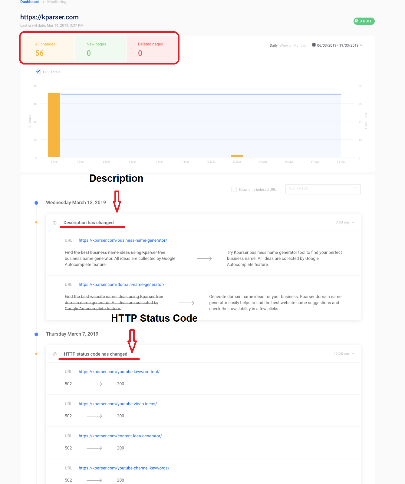
- Also, you can use extra features like website monitoring to track the most important pages. It is really useful when you want to monitor indexing issues or content changes.
With the help of this software you can track the active number of errors, improve your website health and SEO ranking.
Below are the 5 important factors to consider when doing a website audit:
#1. Backlinks analysis
Backlinks are the external links to your website. Each backlink is a piece of a puzzle that plays an important role in indexing. The sources and quantity of web page backlinks define the importance of a page and how a search engine decides on the order of link display. Backlinks help to attract a primary audience but remember that quantity doesn’t always define the quality. Strong website architecture requires fewer backlinks. During analysis, you may stumble upon information that will become helpful for improving general design.
Sitechecker Pro users can check essential backlink parameters. You can start from the Free Backlink Checker: the more reliable the website is that you choose, the better it influences your reputation. The best way is to come up with a short list of trusted websites for efficient backlinks is to use Sitechecker Pro for primary analysis and then do some manual work. A check feature analyses the number of links and domains and then creates a report with trusted themes for all URL addresses. You can look through the top 10 or 20 positions to check everything closely.
Indexing data is also displayed in Backlink Checker Report, helping you to attract attention of search engines to the important information. Make sure all the important information is indexed. In Sitechecker, users can also view all
404 error pages and
redirect chains and reclaim the ones that are not working.
#2. Anchors analysis
The next step will define whether your links include spam or irrelevant anchors. Anchors are a powerful tool that can either take your website to the top or result in sanctions and blockage. It depends on how good you are at using them.
An anchor is a text part of a link – a clickable content that disguises a portal to another page. This text usually consists of keywords inserted directly in the sentence. The more relevant the anchor is, the more significant weight is transmitted by the link. This relevance lies in the relationship between text and link: it should be obvious and logical. Sometimes it is useful to break the main search of synonyms and epithets to make anchors more diverse. There is no perfect strategy for optimal anchor choice. Analyze the choice of competitive web resources and find the most efficient option.
What is your best chance to analyze anchors? The answer is – anchor cloud.
If you can`t afford majestic tool, there is a free one from Sitechecker. It shows anchors to every backlink you would like to track.
With this information you can:
- Analyze anchor text. If it is not suitable for your business or contain spam words, you have to remove or decline such backlinks. Otherwise, you can get a penalty or warnings from search engines.
- Explore the topic. Google likes websites which relevant links. If your blog is about Tech but all the backlinks are left from Fashion blogs, there is a big reason to wonder whether you are a spammer.
- Check external backlinks. It will help you to determine which sites are suitable for you.
#3. Internal links analysis
Now, let’s pay attention to internal structure and navigation. A convenient menu is just the tip of the iceberg. For better performance, you need to create an integral infrastructure and interlink the pages within the website. Besides convenience, this step increases the thematic and statistic weight of the website. The more links lead to a particular page, the more weight it carries. Smart distribution of internal links has a positive influence on indexation results, especially if your website consists of four or more pages. The connections should be logical and help a user to find information faster. Make sure there are no broken links or irrelevant anchors.
You can receive the full list of the links that are used for website ranking through Majestic Site Explorer. It is possible to get the list of links found on your website currently and those that were used before. You can see what is working, what is effective, and what needs to be fixed. For instance, some pages were closed or deleted, but you kept sending traffic there. You can solve the problem with a full report of the issues.
For these purposes you can try website health checker from Sitechecker. Launch website audit and get the information about all technical errors. You can find 404 error pages, check their anchors and remove from your website.
#4. Analysis of the competitors
It is important to know your rivals and what is going on in the industry. The analysis of the competitors is crucial for making strategic decisions and understanding the place of your project within the market.
To choose the competitors for tracking, you can use keyword analysis via Majestic. Even if you know your rivals, there is a chance to stumble upon some strong candidates with promising SEO strategies that can become a threat in the future. If you have many keywords in common an analyzed website is your direct rival. If its visibility is high, it probably uses the right strategy for SEO optimization.
You need to compare the frequency of visits, the number of indexed pages,
keyword density, structure and content, interlinking, etc. You can analyze general features and specific approaches that are important for promotion such as domain age, the number of visitors, meta information, and linking strategy. This data will help you to come up with new ideas and a fresh approach to your own web resource.
#5. Data examining and monitoring
Tracking reports help to keep a check on server uptime, download speed, viruses, and even changes on pages, similar to indexation status and robots.txt file status, and page code. Why is this so important? With time, new people get involved in the working process, the majority with little understanding of SEO. You can explain the basics but monitoring the changes wouldn't go amiss.
You should scan websites to detect such changes and view all notes regarding them in a journal. Great feature getting mails from special when new links are added and get updates on their status.
It is possible to get complete SEO reports on the backlinks to compare their value. Keep monitoring the key competitors to get the reports on the relevant link building campaigns every 10 days. Track the important keywords and compare those with competitors’ performance, too.
Conclusion - How an audit benefits your website
A website audit is a set of complex measures that require time and analysis that help with:
- behavioral factors improvement;
- organic traffic increase;
- higher position in search results;
- conversion enhancement;
- and better perspectives for monetization.
When you need to detect all issues of the websites functioning and analyze the competitive environment, choose a comprehensive audit which includes a technical audit, SEO analysis, usability check, and a marketing audit.
The technical audit is aimed at analyzing hosting, website coding, website management features, software vulnerability, loading time, etc. SEO audit shows website success regarding its rating in search engines. You are to investigate content quality, external links, indexed pages, the correctness of titles and meta tags. The purpose of a usability check is to detect how convenient your website is for users by studying website design and analyzing the ease of technical manipulations, such as entry and exit and filling in electronic applications. The final stage helps to make sure the website is compliant with the requests of the target audience and has advantageous differences compared with competitors’ websites.
A website audit is a significant step in upgrading your web resource, and it should not be neglected. Timely and high-quality analysis ensures the stable and efficient functioning of a website. Conducting an audit on a regular basis guarantees that your web resource will occupy high positions in the search results and ensure new customers.