ESP32 Low Power Modes

Hello readers, hope you all are doing great. In this tutorial, we will discuss low power modes in ESP32, their purpose and their implementation to increase the battery life by reducing power consumption.

Where To Buy?
No.ComponentsDistributorLink To Buy
1ESP32AmazonBuy Now

Purpose of Low Power Modes

Fig.1

Along with multiple wireless and processing features, ESP32 also provides us with a power-saving feature by offering sleep modes. When you are powering the ESP32 module from the live supply using an adaptor or a USB cable, there is nothing to worry about power consumption. But when you are using a battery, as a power source to ESP32, you need to manage the power consumption for longer battery life.

Low Power Modes in ESP32

When ESP32 is in sleep mode, a small amount of power is required to maintain the state of ESP32 in RAM (random access memory) and retain necessary data. Meanwhile, the power supply won’t be consumed by any unnecessary peripheral or inbuilt modules like Wi-Fi and Bluetooth.

ESP32 offers 5 power modes. Each mode is configurable and offers different power-saving capabilities:

  1. Active Mode
  2. Modem Sleep Mode
  3. Light Sleep Mode
  4. Deep Sleep Mode
  5. Hibernation Mode

Fig. 2

Active Mode:

  • In active mode, all the modules and features of ESP32, like processing cores, Wi-Fi, Bluetooth, radio etc. remain active all the time.
  • Most of the power consumption occurs in this power mode which can vary between 160 -240mA and sometimes the maximum consumption could reach up to 790mA (when both Wi-Fi and Bluetooth are enabled or active at the same time).

Modem Sleep Mode:

  • In this mode, radio, Wi-Fi, Bluetooth will be disabled and everything else will remain active. Power consumption in this mode varies from 3 to 20mA.
  • Sleep modes can switch between modem and active modes as per the predefined intervals, by following the associated sleep pattern.

Light Sleep Mode:

  • During this mode, the central processing unit is paused by turning/powering off its clock.
  • ULP- coprocessor and RTC (real-time clock) remain active during light sleep mode and power consumption is 0.8mA.

Deep Sleep mode:

  • In this mode, the Ultra Low Power (ULP) coprocessor remains active while the ESP32 core and other digital peripherals remain inactive.
  • The ULP coprocessor wakes up the core processor when required.
  • The amount of power consumed in this mode is 10uA.

Fig 3

Hibernation Mode:

    • In this mode, the ULP coprocessor and internal oscillator both are disabled.
  • Only a real-time clock (RTC) remains active to wake up the processor and other required modules from hibernation mode and the power consumption in this mode is extremely low that is approximately 2.5uA.

For a better understanding of low power modes in ESP32, we are going to implement deep sleep mode in esp32 and will also discuss how to wake up the device from deep sleep mode.

Deep Sleep mode and Wakeup Using Capacitive Touch-sensitive pins

To implement deep sleep modes we are going to use another ESP32 feature that is Capacitive Touch Sensing pins. These pins can sense the presence of a body that holds an electric charge.

So we are going to use these touch-sensitive pins for waking up ESP32 from deep sleep mode using the Arduino IDE compiler.

In Arduino IDE examples are given for deep sleep mode with various wake-up methods.

  • Follow the image attached below to open the example code:

Fig. 4 Example code.

  • Arduino IDE Code

#define Threshold 40 /* Greater the value, more the sensitivity */ RTC_DATA_ATTR int bootCount = 0; touch_pad_t touchPin; /* Method to print the reason by which ESP32 has been awaken from sleep */ void print_wakeup_reason(){ esp_sleep_wakeup_cause_t wakeup_reason;   wakeup_reason = esp_sleep_get_wakeup_cause();   switch(wakeup_reason) { case ESP_SLEEP_WAKEUP_EXT0 : Serial.println("Wakeup caused by external signal using RTC_IO"); break; case ESP_SLEEP_WAKEUP_EXT1 : Serial.println("Wakeup caused by external signal using RTC_CNTL"); break; case ESP_SLEEP_WAKEUP_TIMER : Serial.println("Wakeup caused by timer"); break; case ESP_SLEEP_WAKEUP_TOUCHPAD : Serial.println("Wakeup caused by touchpad"); break; case ESP_SLEEP_WAKEUP_ULP : Serial.println("Wakeup caused by ULP program"); break; default : Serial.printf("Wakeup was not caused by deep sleep: %d\n",wakeup_reason); break; } }   /* Method to print the touchpad by which ESP32 has been awaken from sleep */ void print_wakeup_touchpad(){ touchPin = esp_sleep_get_touchpad_wakeup_status();   switch(touchPin) { case 0 : Serial.println("Touch detected on GPIO 4"); break; case 1 : Serial.println("Touch detected on GPIO 0"); break; case 2 : Serial.println("Touch detected on GPIO 2"); break; case 3 : Serial.println("Touch detected on GPIO 15"); break; case 4 : Serial.println("Touch detected on GPIO 13"); break; case 5 : Serial.println("Touch detected on GPIO 12"); break; case 6 : Serial.println("Touch detected on GPIO 14"); break; case 7 : Serial.println("Touch detected on GPIO 27"); break; case 8 : Serial.println("Touch detected on GPIO 33"); break; case 9 : Serial.println("Touch detected on GPIO 32"); break; default : Serial.println("Wakeup not by touchpad"); break; } }   void callback(){ //placeholder callback function }   void setup(){ Serial.begin(115200); delay(1000); //Take some time to open up the Serial Monitor   //Increment boot number and print it every reboot ++bootCount; Serial.println("Boot number: " + String(bootCount));   //Print the wakeup reason for ESP32 and touchpad too print_wakeup_reason(); print_wakeup_touchpad();   //Setup interrupt on Touch Pad 3 (GPIO15) touchAttachInterrupt(T3, callback, Threshold);   //Configure Touchpad as wakeup source esp_sleep_enable_touchpad_wakeup();   //Go to sleep now Serial.println("Going to sleep now"); esp_deep_sleep_start(); Serial.println("This will never be printed"); }   void loop(){ //This will never be reached }

Code Description

  • The first step is to set the threshold value for touch-sensitive pins.
  • When a body, containing an electric charge touches a touch-sensitive pin, the threshold value decreases below 40, that decrease in the threshold value will make ESP32 wake up from deep sleep mode. In the example code threshold value is 40.
  • The next task is to store the data into RTC memory (using RTC_DATA_ATTR ) because in deep sleep mode only RTC remains active and all other peripherals, processors, wireless modules will be disabled.
  • ESP32 offers 8kB SRAM on RTC to store the data.
  • But when you press EN/reset button the data stored in RTC memory will also be erased.
  • bootCount an integer type variable is used to count the number of times ESP32 has woken up during sleep mode. The value of bootCount variable is stored in RTC memory.
  • The print_wakeup_reason() function is used to print the reason for ESP32 wakeup from deep sleep whether it is due to an external interrupt, timer, or touch-sensitive pins.
  • The ESP32 has multiple capacitive touch-sensitive GPIO pins which can be used to wake up esp32 from deep sleep mode.
  • Print_wakeup_touchpad() function is used to print the GPIO pin which made ESP32 wake up from sleep mode.
  • When you hold a capacitive sensitive pin for a longer duration the threshold value (initialized globally) decreases from its predefines value i.e., 40 which will cause ESP32 to wake up, at that time the callback() function comes into action.
  • This function will be used as an argument inside the touchAttachInterrupt() function.

Setup()

  • Inside the setup() function the first task is to start the serial monitor with a baud rate of 115200.
  • Next, if there is any increment in boot count due to wake up calls, then print that count on the serial monitor.

Call the respective functions to print the wake-up reason:
  • Print_wakeup_reason() is used to print whether the ESP32 wake-up is caused by an external interrupt, timer or a capacitive sensitive pin.
  • If the wake up is due to a capacitive sensitive pin then the print_wakeup_touchpad() function will print the GPIO pin number which caused the wake-up.
  • The next task is to attach the interrupt using touchAttachInterrupt() function, to capacitive sensitive GPIO pin which you will use to wake up ESP32.
  • In this example we are using GPIO 15 capacitive sensitive pin as a wakeup interrupt pin.
  • esp_sleep_enable_touchpad_wakeup() is used to enable touch sensor feature.
  • esp_deep_sleep_start() function is used to make ESP32 enter to deep sleep mode.
  • Once ESP32 enters the sleep mode no other operation or data communication is possible until it receives a wakeup call.

Fig 12

Loop()

  • In this example code, there is nothing, written inside the loop function. But you can change the code as per your requirements.

Code Testing

  • To test the code, use a connecting wire (male to female) and connect one side to ESP32’s touch-sensitive pin (which you have mentioned in the code as an interrupt).
  • When you touch that pin an interrupt will be generated to wake ESP32 from sleep.
  • You can see the results on a serial monitor or can check the current consumption or can run other functions once it is awake like blinking LED.
  • In this code, we are using GPIO_15 touch-sensitive pin.

Fig. 13 waking up esp32 using capacitive sensitive GPIO pin

We have attached a screenshot from the serial monitor for reference.

Fig. 14

Deep Sleep mode and Wakeup Using Interrupt method

Arduino IDE Code

#define uS_TO_S_FACTOR 1000000ULL /* Conversion factor for micro seconds to seconds */ #define TIME_TO_SLEEP 5 /* Time ESP32 will go to sleep (in seconds) */ RTC_DATA_ATTR int bootCount = 0; /* Method to print the reason by which ESP32 has been awaken from sleep */ void print_wakeup_reason(){ esp_sleep_wakeup_cause_t wakeup_reason; wakeup_reason = esp_sleep_get_wakeup_cause(); switch(wakeup_reason) { case ESP_SLEEP_WAKEUP_EXT0 : Serial.println("Wakeup caused by external signal using RTC_IO"); break; case ESP_SLEEP_WAKEUP_EXT1 : Serial.println("Wakeup caused by external signal using RTC_CNTL"); break; case ESP_SLEEP_WAKEUP_TIMER : Serial.println("Wakeup caused by timer"); break; case ESP_SLEEP_WAKEUP_TOUCHPAD : Serial.println("Wakeup caused by touchpad"); break; case ESP_SLEEP_WAKEUP_ULP : Serial.println("Wakeup caused by ULP program"); break; default : Serial.printf("Wakeup was not caused by deep sleep: %d\n",wakeup_reason); break; } }   void setup(){ Serial.begin(115200); delay(1000); //Take some time to open up the Serial Monitor   //Increment boot number and print it every reboot ++bootCount; Serial.println("Boot number: " + String(bootCount));   //Print the wakeup reason for ESP32 print_wakeup_reason();   /* First we configure the wake up source We set our ESP32 to wake up every 5 seconds */ esp_sleep_enable_timer_wakeup(TIME_TO_SLEEP * uS_TO_S_FACTOR); Serial.println("Setup ESP32 to sleep for every " + String(TIME_TO_SLEEP) + " Seconds");   /* Next we decide what all peripherals to shut down/keep on By default, ESP32 will automatically power down the peripherals not needed by the wakeup source, but if you want to be a poweruser this is for you. Read in detail at the API docs http://esp-idf.readthedocs.io/en/latest/api-reference/system/deep_sleep.html Left the line commented as an example of how to configure peripherals. The line below turns off all RTC peripherals in deep sleep. */ //esp_deep_sleep_pd_config(ESP_PD_DOMAIN_RTC_PERIPH, ESP_PD_OPTION_OFF); //Serial.println("Configured all RTC Peripherals to be powered down in sleep");   /* Now that we have setup a wake cause and if needed setup the peripherals state in deep sleep, we can now start going to deep sleep. In the case that no wake up sources were provided but deep sleep was started, it will sleep forever unless hardware reset occurs. */ Serial.println("Going to sleep now"); Serial.flush(); esp_deep_sleep_start(); Serial.println("This will never be printed"); }   void loop(){ //This is not going to be called }

Code Description

  • The first task is, to define the timer period for which ESP32 will be in deep sleep mode.
  • As we know that ESP32 operates at the MHz frequency range so the timer will be in microseconds. So, it is required to convert the time into seconds.
  • To add a timer of 5sec we need to multiply 5*1000000.
  • bootCount an integer type variable is used to count the number of times ESP32 has woken up during sleep mode. The value of bootCount variable is stored in RTC memory.

Fig 15

  • The print_wakeup_reason() function is used to print the reason for ESP32 wakeup from deep sleep whether it is due to an external interrupt, timer or touch-sensitive pins.

Fig. 16

Setup()

  • As discussed earlier, inside the setup function first we need to initialize the serial monitor at 115200 baud rate and then print the value of bootCount variable which is incrementing every time a wakeup interrupt occurs.

Fig. 17

  • The esp_sleep_enable_wakeup() function is used to enable the timer to generate a timer interrupt by passing time in microsecond as an argument.
  • In the beginning of code we have defined some global variable to add 5 sec timer (or 5000000us) and after every 5 sec ESP32 should wake up from deep sleep till 5 sec.

Fig. 18

  • esp_deep_sleep_start() function is used to make ESP32 enter the deep sleep mode.

Fig. 19

Testing

  • You can see the results of above code on serial monitor as shown is the image attached below.

Fig 20

This concludes the tutorial. I hope you found this useful, and I hope to see you soon for the new ESP32 tutorial.

ESP32 PWM(Pulse Width Modulation) in Arduino IDE

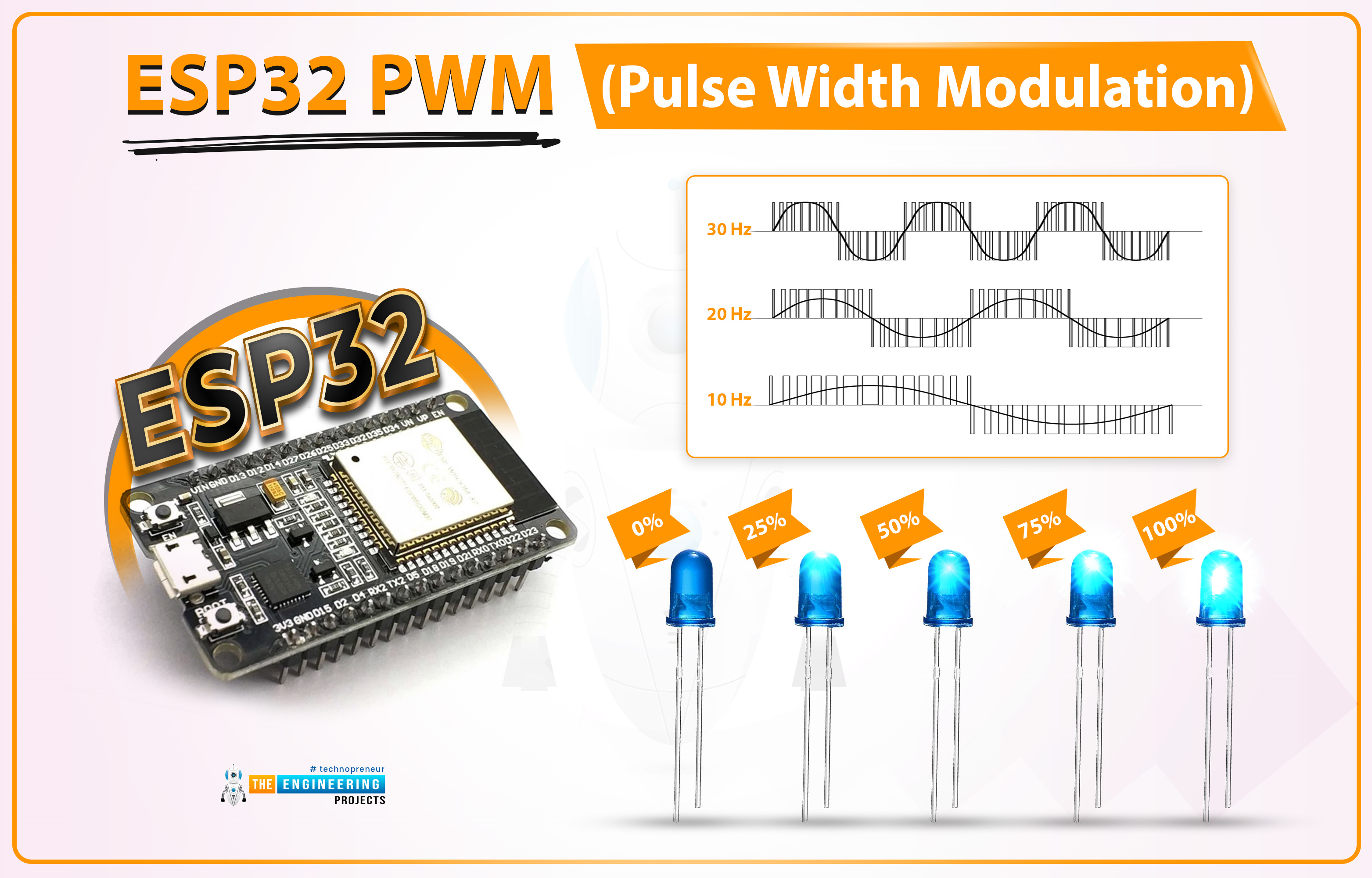
Hello readers, I hope you all are doing great. Welcome to the 3rd Lecture of Section 2 in the ESP32 Programming Series. In this tutorial, we are going to discuss another important feature of ESP32 i.e. PWM(Pulse Width Modulation).

Pulse Width Modulation is a technique to reduce the voltage by pulsating it. In today's lecture, we will first understand the basic concept of PWM, and after that will design two projects to fully grasp it. In the first project, we will control the brightness of an LED, while in the second one, we will control the speed of a DC Motor.

  • Here's the video demonstration of PWM Control in ESP32:

Before going forward, let's first have a look at the PWM working:

Where To Buy?
No.ComponentsDistributorLink To Buy
1ESP32AmazonBuy Now

What is Pulse Width Modulation?

PWM is used to control the power delivered to the load by pulsating the ON-Time of the voltage pulse, without causing any power loss. Let's understand the PWM concept with the help of below image:

  • As you can see in the above image, Figure A shows a simple 5V DC signal.
  • Figure D shows a simple circuit with a manual switch, now if we turn the switch ON & OFF manually, the Load will also behave in the same way. Its waveform is shown in Figure B, when the switch is ON, we are getting +5V and when it's OFF, output is 0V.
  • Instead of manual switching, if we place a fast automatic switching circuit (FETs, MOSFETs etc.), the output pulse won't show fluctuations, instead, it will get steady but its overall power will be reduced.
  • Let's understand the working of PWM with an example:

Suppose a DC Motor runs at 200RPM over 5V. Now, if we want to reduce its speed to 100 RPM, we need to reduce its input voltage to 2.5V(approx). So, either we can replace the 5V battery with a 2.5V Battery or use a PWM circuit to reduce the voltage level from 5V to 2.5V. In this specific case, the PWM pulse will be ON for 50% of the time and get OFF for the remaining 50% of the time.

The behavior of the PWM signal is determined by the following factors:

  • Frequency
  • Duty Cycle
  • Resolution

PWM Frequency:

  • The Frequency of a signal is defined as the number of cycles per second, denoted by "f" and the measuring unit is hertz(Hz).
  • The Frequency (f) of a signal is inversely proportional to its time period(t).
  • Let's understand the signal Frequency with the help of below image:

As you can see in the below figure, we have taken two signals for a duration of 1 second. The first signal completes 10 Cycles in 1 second, so we can say it has a frequency of 10Hz, while the second one has a frequency of 5Hz as it completes 5 cycles in 1 second. So, I hope now it's clear that the number of cycles per second is the frequency of a signal.

  • The frequency of a PWM signal depends on the provided clock source.
  • In the case of microcontrollers, the clock source is provided by the crystal oscillator. So, a 40MHz Crystal Oscillator can produce high-frequency PWM signals as compared to a 20MHz oscillator.

PWM Duty Cycle:

Duty Cycle is the ratio of ON time(when the signal is high) to the total time taken to complete the cycle. The duty cycle is represented in the form of a percentage (%) or ratio. Let's understand the PWM Duty Cycle with the help of below image:

  • The 1st graph shows no signal, so we can say it has a 0% Duty Cycle because there's no ON-Time.
  • The 2nd graph shows 5 cycles of a signal and in each cycle, the signal is ON only for 25% of the total time. So, its Duty Cycle is 25%.
  • In the 3rd graph, the signal has a duty cycle of 50% because it's HIGH for 50% of the cycle.
  • You can calculate the 4th graph, its duty cycle is 75% as it is HIGH for 75% of the total duration.
  • The last graph shows a pure DC Signal of 5V, and as it is HIGH for the whole cycle, its duty cycle will be 100%.

Resolution:

The resolution of a PWM signal defines the number of steps it can have from zero power to full power. The resolution of the PWM signal is configurable for example, the ESP32 module has a 1-16 bit resolution, which means we can configure maximum a of 65536 (2^16) steps from zero to full power.

Implementing PWM using ESP32

In the ESP WROOM-32 module, there are 16 PWM channels. All the channels are divided into two groups containing 8 channels in each group. The resolution can be programmed between 1 to 16 bits and frequency also depends upon the programmed resolution of the PWM signal.

Now

For the demonstration of PWM in ESP32 we are going to explain two examples:

  1. Controlling LED brightness using PWM
  2. Controlling DC motor speed using PWM

ESP32 Code for Controlling LED brightness using PWM

We are using Arduino IDE to compile and upload the code into the ESP WROOM-32 board.

  • If you are new to Arduino IDE and ESP32 then follow our previous tutorial, Introduction to ESP32 programming series for detailed information.
  • ESP32’s inbuilt LED is used in this code. You can also connect an external LED as per your requirements.

Arduino IDE Code:

// Global variable declaration to set PWM properties
const int ledChannel = 0; // select channel 0
const int resolution = 8; //8-bit resolutin i.e., 0-255
const int frequency = 5000; // set frequency in Hz
int dutyCycle = 0;

void setup()
{
    Serial.begin(115200);
    ledcSetup(ledChannel, frequency, resolution); // configure LED PWM functionalities
    ledcAttachPin(LED_BUILTIN, ledChannel); // attach the channel to the GPIO to be controlled
}

void loop()
{
    while(dutyCycle <200)
    {
        ledcWrite(ledChannel, dutyCycle++); // changing the LED brightness with PWM
        Serial.print(" duty Cycle ++ :");
        Serial.println(dutyCycle); // display the duty cycle on serial monitor
        delay(5);
    }
    while(dutyCycle>0)
    {
        ledcWrite(ledChannel, dutyCycle--); // changing the LED brightness with PWM
        Serial.print(" duty Cycle -- :");
        Serial.println(dutyCycle); // display the duty cycle on serial monitor
        delay(5);
    }
}

Code Description

Global Variable declaration:
  • The first step is to declare variables for setting PWM properties.
  • As we have already mentioned that ESP WROOM-32 has 16 PWM channels (0 to 15). So, the first step will be to select a PWM channel between 0-15. In the Arduino IDE code, we are using PWM channel_0 to generate a PWM signal.
  • The next step will be to choose the resolution. The maximum resolution for ESP32 is 16-bit. You can choose any value between 1-16. PWM resolution is the factor that decides the maximum duty cycle.
  • For example, if we choose 10-bit resolution then the maximum duty cycle of the output signal will be 2^10 that is 1024 (0-1023) and similarly, for 8-bit resolution the duty cycle will be 2^8=256 (0- 255).
  • 5KHz or 5000Hz is the PWM signal frequency.
  • We also need to initialize a variable to store the duty cycle value.

// Global variable declaration to set PWM properties
const int ledChannel = 0; // select channel 0
const int resolution = 8; //8-bit resolutin i.e., 0-255
const int frequency = 5000; // set frequency in Hz
int dutyCycle = 0;

Arduino Setup() Function

  • Inside setup() function we are going to start serial monitor at 115200 baud rate.

Serial.begin(115200);
  • To configure PWM properties we are calling the ledcSetup() function which uses PWM properties (like PWM channel, frequency and PWM resolution) as arguments.

ledcSetup(ledChannel, frequency, resolution); // configure LED PWM functionalities
  • ledcAttachPin() function is used to assign the LED_BUILTIN pin to the PWM channel.

ledcAttachPin(LED_BUILTIN, ledChannel); // attach the channel to the GPIO to be controlled

Arduino Loop() Function

  • Inside the loop function, we going to run a conditional control loop (while loop) to change the LED brightness along with the change in duty cycle.
  • At first, the value of the duty cycle is going to increase continuously until it reaches max 8-bit resolution ( that is 255).
  • The serial monitor will print the duty cycle value with some delay.

while(dutyCycle <200)
    {
        ledcWrite(ledChannel, dutyCycle++); // changing the LED brightness with PWM
        Serial.print(" duty Cycle ++ :");
        Serial.println(dutyCycle); // display the duty cycle on serial monitor
        delay(5);
    }

  • After increasing the duty cycle to maximum resolution another while loop is used to decrease the duty cycle to value 0 from 255 and proportionally the LED brightness and the PWM output will be printed on the serial monitor.

while(dutyCycle>0)
{
    ledcWrite(ledChannel, dutyCycle--); // changing the LED brightness with PWM
    Serial.print(" duty Cycle -- :");
    Serial.println(dutyCycle); // display the duty cycle on serial monitor
    delay(5);
}

Code Testing

  • You can see the change in the value of the duty cycle on the serial monitor. We have attached a screenshot below from the Arduino IDE serial monitor for reference.

  • For a better understanding of PWM output you can use an oscilloscope (either CRO or DSO) by connecting the PWM output pint and GND pint to the oscilloscope probe, if available.
  • You can also use a serial plotter to see the PWM output if you do not have an oscilloscope.
  • To access the serial plotter, use sort-cut key shift+ctrl+L or follow the image attached below:

Fig. 8 Arduino IDE Serial Plotter

  • We have attached a screenshot of the PWM output waveform from the serial plotter for better understanding.
  • You can vary the value of duty cycle anywhere between 0-8 bit resolution.
  • For example in the image attached below the duty cycle is 200.

Fig. 9 Serial plotter PWM output

ESP32 Code for Controlling DC motor speed using PWM

Fig. 10

In this example, we are going to implement PWM using ESP WROOM-32 to control the speed of a DC motor.

The speed of the DC motor depends upon the input power supply. So, by varying the power input we can also vary (increase or decrease) the speed of DC motor.

Hardware components required:

  • ESP WROOM-32 board
  • DC motor
  • L298N motor driver
  • Connecting wires
  • Data cable

L298N motor driver: A motor driver is used between the ESP32 board and DC motor to resolve the power compatibility issues.

Both the ESP32 board and DC motor operate at different power ratings due to which you can not connect the two devices directly. So a motor driver is used to receive a low power input from the ESP32 board and drive/run DC motor at slightly high power.

L298N can drive a DC motor that operated between 5 to 35 voltage range and maximum current of 2A.

There are various DC motor drivers available in the market for example L293D, DRV8833, MAX14870 single brushed motor driver etc. You can choose the driver of your choice depending upon the application and power ratings.

Fig. 11

FIG. 12 IC L298N pin-out

  • You can also change the direction of rotation by connecting the input as per the table drawn below:
IN_1 IN_2 Rotation
HIGH LOW DC motor rotates in a clockwise direction
LOW HIGH The motor rotates in an anti-clockwise direction
LOW LOW Motor STOP
HIGH HIGH Motor STOP

Table 1

Arduino Code

//configure GPIO pins to connect motor driver
int enable1Pin = 14;
int M_Pin1 = 26;
int M_Pin2 = 27;

// Setting PWM properties
const int freq = 10000;
const int pwmChannel = 0;
const int resolution = 8;
int dutyCycle = 150;

void setup()
{
    Serial.begin(115200);

    // sets the pins as outputs:
    pinMode(M_Pin1, OUTPUT);
    pinMode(M_Pin2, OUTPUT);
    pinMode(enable1Pin, OUTPUT);

    //Configure LED PWM functionalities
    ledcSetup(pwmChannel, freq, resolution);

    // attach the channel to the GPIO to be controlled
    ledcAttachPin(enable1Pin, pwmChannel);

    Serial.print("Testing DC Motor...");
}

void loop()
{
    // Move the DC motor in anti-clockwise direction at maximum speed
    Serial.println("Moving reverse");
    digitalWrite(M_Pin1, LOW);
    digitalWrite(M_Pin2, HIGH); 
    delay(500);

    // Move DC motor forward with increasing speed
    Serial.println("Moving Forward");
    digitalWrite(M_Pin1, HIGH);
    digitalWrite(M_Pin2, LOW);

    //----while loop----
    while (dutyCycle <= 255)
    {
        ledcWrite(pwmChannel, dutyCycle); 
        Serial.print("Speed increasing with duty cycle: ");
        Serial.println(dutyCycle);
        dutyCycle = dutyCycle +5;
        delay(100);
    }

    while (dutyCycle >150)
    {
        ledcWrite(pwmChannel, dutyCycle); 
        Serial.print("Speed decreasing with duty cycle: ");
        Serial.println(dutyCycle);
        dutyCycle = dutyCycle -5;
        delay(100);
    }

    // _____Stop the DC motor
    Serial.println("STOP DC motor");
    digitalWrite(M_Pin1, LOW);
    digitalWrite(M_Pin2, LOW);
    delay(500);
}

Code Description

  • The first step is to configure GPIOs which are to be connected with the DC motor driver (L298N).
  • Here we are using three GPIOs, the first one is connected with the Enable_A pin and the rest of the two are connected with motor inputs.
  • You can also control 2 motors with the same driver using Enable_2 and its respective input pins.

//configure GPIO pins to connect motor driver
int enable1Pin = 14;
int M_Pin1 = 26;
int M_Pin2 = 27;
  • The next step is to define variables to store PWM properties as discussed in the previous example.
  • You can vary the frequency and duty cycle of the PWM signal as per your requirements but, within the desired range.
  • Here we are assigning 10000Hz or 10KHz frequency with 8-bit resolution (0-255 duty cycle) and the initial duty cycle value is 150 for PWM channel 0.

// Setting PWM properties
const int freq = 10000;
const int pwmChannel = 0;
const int resolution = 8;
int dutyCycle = 150;

Arduino Setup() Function

  • Inside the setup function, the first task is to initialize the serial monitor with a 115200 baud rate.

Serial.begin(115200);
  • Set the operating mode of three GPIO pins (which are to be connected with motor driver board) as output.

// sets the pins as outputs:
pinMode(M_Pin1, OUTPUT);
pinMode(M_Pin2, OUTPUT);
pinMode(enable1Pin, OUTPUT);

  • Call the function ledcSetup() to configure PWM properties by passing PWM properties as arguments.

//Configure LED PWM functionalities
ledcSetup(pwmChannel, freq, resolution);
  • Next, you need to select the GPIO pin which will provide the PWM output from ESP32 to the motor driver using ledcAttachPin() function which uses the PWM output pin and PWM channel as two arguments.

// attach the channel to the GPIO to be controlled
ledcAttachPin(enable1Pin, pwmChannel);

Arduino Loop() Function

  • Start rotating the motor in the anti-clockwise direction. Follow Table 1 for more details regarding the direction of rotation.
  • Add the delay of 0.5 sec or as per your requirements.

Fig. 19

  • Rotate the DC motor in a clockwise direction by setting M_PIN1 as high ND m_Pin2 as low.

Fig. 20

  • As we have initialized the duty cycle variable with a value of 150. Now, increase the motor speed by increasing the value of the Duty cycle from 150 by increasing 5 steps continuously until it reaches the maximum value that is 255.

Fig. 21 Increasing speed

  • After reaching the maximum speed at 255 duty cycle, now let's decrease the speed of DC motor till 150 duty cycle with the decrease of 5 steps every time.

Fig. 22 Reducing speed

  • Stop duty cycle by either writing both the motor pins(M_Pin1, M_Pin2) to LOW or HIGH (like XOR gate).

Fig. 23 STOP DC motor

Code Testing

  • For a better understanding, open the serial monitor using shortcut keys ctrl+shift+M.
  • On the serial monitor, you can see the increase and decrease in duty cycle and can compare it with DC motor speed.

Fig. 24 PWM output on serial monitor

  • You can also check the PWM output on the Serial plotter by pressing the ctrl+shift+L keys.
  • It is visible through the waveform that the duty cycle is varying from 150 to 255 and reverse and proportionally the seed of the DC motor.

Fig. 25 PWM output on Serial Plotter

This concludes the tutorial. I hope you found this useful, and I hope to see you soon for the new ESP32 tutorial.

The Complete Guide to Nearshoring 

The nearshoring phenomenon is a global economic trend that has been going on for decades. The phenomenon is defined as moving a company’s operations to a country that is in close proximity to the company’s home base.

Nearshoring offers many benefits in terms of cost savings, but it also has many drawbacks. It can have a negative effect on wages for local workers, and it can also have an impact on the environment if the process involves bringing in outsourced goods from overseas.

To conclude, nearshoring often benefits both companies and consumers who are looking for affordable goods at low prices. However, it can have a negative effect on wages and local jobs in the long run.

It's a great way for companies with smaller budgets to have more resources for other aspects of their business. However, it isn't without its challenges. For starters, a company will need someone on-shore to manage the team abroad and provide direction on how things should be done. In addition, there are cultural differences that may need to be addressed - such as different time zones or mores that may not line up with American values.

Why Nearshoring is Becoming so Popular

Nearshoring is becoming more popular because of the benefits it offers for both the outsourcing company and the nearshore company.

Nearshore outsourcing provides cost savings to companies that are looking to outsource their work. It offers lower overall risk than offshore outsourcing through the protection of intellectual property and by having better communications with the workforce.

While offshoring has been around for decades, nearshoring started gaining popularity in recent years due to its relative proximity to home markets, enabling companies to make quick decisions about products, services, marketing approaches, etc., which can be challenging when you are thousands of miles away. Nearshoring is appealing because it provides cost savings and lower risk than offshoring.

Why Is Nearshoring Useful?

Nearshoring is a strategic sourcing technique that can be used to lower the cost of labor. It is also helpful in reducing the production lead time by enabling production capacity to be shared among different regions while centralizing key functions.

Nearshoring allows companies to take advantage of low-cost labor without having to relocate their manufacturing facilities. Through nearshoring, companies are able to maintain control over design and marketing while lowering production costs through outsourcing manufacturing processes abroad for example in China or India.

What Countries Offer a Nearshore Workforce?

There are many countries in the world that offer a nearshore workforce and they differ in terms of their cost and quality. Some countries like India and China, with low labor costs and large populations, are popular outsourcing destinations. Other countries such as Indonesia and Malaysia, offer higher quality work based on their educational system. Nearshoring in Europe is also becoming more and more popular because of the low costs and good quality of the work.

There are many factors to take into account when outsourcing business processes or operations to a country. The type of work you need to be done will determine the country you choose for your operations, but there is one key factor that is often overlooked: the availability of human capital. Countries vary in terms of how educated their population is and what languages they speak, which can give an edge when it comes to choosing a country for your overseas operations.

What are the Disadvantages of Nearshoring?

  1. Language barriers can lead to communication breakdowns.
  2. The more time zones that are involved, the more likely it is that the business will be interrupted by time zone differences.
  3. Cultural differences may lead to some employees feeling uncomfortable with their working environment and may even cause some employees to quit because they do not want to work in an environment where they do not feel welcome or appreciated.
  4. High turnover rates among offshore workers will mean that more effort has to be spent on training new employees.

The most prominent disadvantage is that organizations will lose vital skills and know-how when they outsource their projects. They may also lack the flexibility in decision-making for both short and long-term goals due to limitations on management decisions brought about by working with a third-party company. Organizations will also have a difficult time transferring any of their employees to different locations if they decide they want them closer to home in order for them to take care of family issues or have more opportunities for growth.

5 Ways to Prevent Your Car from Being Stolen

Hello friends, I hope you all are doing great. In today's tutorial, we will have a look at the 5 Ways to Prevent Your Car from Being Stolen. Every year over 720,000 motor vehicles are stolen, according to the official site of the United States government. Thieves have gotten savvy, using technology and new methods to make stealing cars easier than ever. It is crucial to take steps to protect your vehicle from being stolen. Here are five ways to do just that:

Install a Security System

A good security system includes an alarm, immobilizer, and battery backup if you lose power to your car for any reason. It should have a remote lock/unlock capability which can be helpful if someone finds or steals your keys. You can even get systems these days that notify you on your phone if someone is trying to start your car.

The system should also have a GPS vehicle tracking device if your car is stolen. The police can track the car down and return it to you. The GPS device should enable you to monitor your car and what routes they have taken. Some of these devices will even allow you to set up alerts if the vehicle has been moved at any time during its idle state, which is excellent for catching thieves in action and alerting authorities immediately.

An added benefit of using a GPS tracking service is protecting your car from being towed. If thieves tow your vehicle, you can log into the service and search to see where it has been taken so that you know who stole it and call authorities immediately.

An excellent security system needs to be fitted with an alarm that will go off when someone unauthorized tries to open the car. The louder and more intrusive the alarm, the better. This way, the car's owner will be notified of a possible theft attempt and take precautions. You need to choose an alarm that alerts you when the car is being tampered with and one that can be activated remotely.

Steering Locks and Wheel Clamps

One way to prevent your car from being stolen is to install a steering lock. This will make it difficult for thieves to drive off with the car. There are a few different types of steering locks available on the market. A popular type is the club lock, which wraps around the steering wheel and prevents it from being turned.

Another option is to install a car alarm with a steering lock feature. This will sound an alarm if someone tries to move the car. Some cars come with a built-in steering lock that is activated when turned off.

If your car doesn't have a built-in steering lock, you can buy an aftermarket one to use. Whichever option you choose, make sure to properly secure the steering lock so that it cannot be easily removed. Another option is to use a wheel clamp. This will immobilize the car and make it difficult for thieves to steal.

Both of these solutions are a great deterrent against car theft and will help to protect your vehicle. Be sure to use them if you are concerned about your car being stolen.

Lock Your Car

This may seem like a no-brainer, but many people forget to do this essential step. Make it a habit to always lock your car doors and windows when you're not in it. This will make it more difficult for thieves to access your vehicle. If you're not in a hurry, you can also roll up your windows all the way and shut the doors.

If someone stops next to your car asking for help or directions, don't get out. Stay in your car and keep the doors locked. This allows criminals to unlock it from outside of the vehicle. Many times they will open already unlocked cars with this tactic.

The simplest thing you can do to keep your car from being stolen is always to lock your doors after getting out or entering the vehicle. This is especially important if you habit leaving your car running when you run into the store.

Park in a Well-Lit Area

If you park your car in a well-lit area, it will be less likely to be targeted by thieves. Try to avoid parking in isolated or dark areas whenever possible. If you have a garage, use it.

If you have to park on the street, try finding a well-lit spot near other cars. This will make your vehicle less of a target for thieves. In a public parking lot, always park in an area close to the entrance and visible.

If you park under a tree, try to avoid parking near an overhanging branch that thieves could use as leverage for opening your car door or climbing inside. If possible, choose brightly lit areas with surveillance cameras nearby so the footage can be used to identify thieves in case they steal your vehicle.

When looking at potential spots to park, always be aware of your surroundings and look for any suspicious activity. If you see anything that makes you uncomfortable, find another spot to park in.

Don't Leave Valuables in Your Car

One of the best ways to prevent your car from being stolen is to not leave any valuables in it. If you have expensive items in your car, it will be more likely for thieves to target your vehicle. So, always make sure to take your belongings with you when you exit your car.

If you have to leave something in your car, try to keep it out of sight. You can put it in the trunk or under the seats. If you need to put things in the trunk or in the backseat, make sure to lock them up so that thieves can't get to them. You should also do this before you reach the parking lot so that thieves can't see what you're doing.

Remember, the best way to prevent your car from being stolen is by taking precautions and being vigilant about your surroundings. You can make it much more difficult for thieves to get their hands on your vehicle by following these tips.

Syed Zain Nasir

I am Syed Zain Nasir, the founder of <a href=https://www.TheEngineeringProjects.com/>The Engineering Projects</a> (TEP). I am a programmer since 2009 before that I just search things, make small projects and now I am sharing my knowledge through this platform.I also work as a freelancer and did many projects related to programming and electrical circuitry. <a href=https://plus.google.com/+SyedZainNasir/>My Google Profile+</a>

Share
Published by
Syed Zain Nasir