ESP32 Over The Air (OTA) Web Updater

Hello readers, I hope you are all doing great. In this tutorial, we are going to discuss the OTA web updater on the ESP32.

We already covered the fundamentals of OTA programming in ESP32, in our previous tutorial where we used the Arduino IDE to upload OTA code into the ESP32 module using the network port.

In the OTA web updater, you need to create a web server page for OTA programming.

[caption id="attachment_166886" align="aligncenter" width="1920"] ESP32 OTA web updater[/caption]

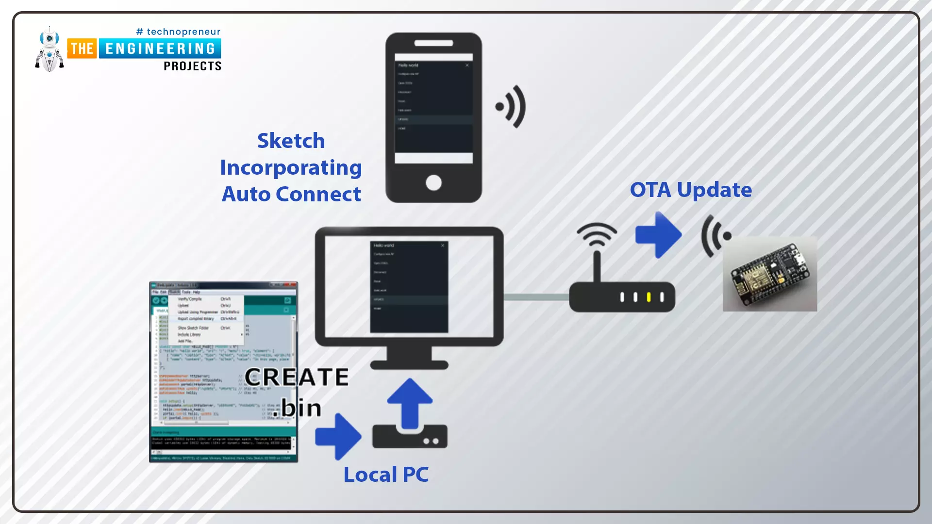
Fig.1 ESP32 OTA web updater

Where To Buy?
No.ComponentsDistributorLink To Buy
1ESP32AmazonBuy Now

Over the Air Web Updater

  • "Over-the-air" refers to the ability to wirelessly download an application, configuration, or firmware to internet-enabled devices, also known as IoT. (OTA). It functions similarly to our computers, laptops, tablets, and phones.
  • Instead of using a serial port and a wired medium to upload a code, the OTA web updater allows the user to update the code or firmware wirelessly via a web server.
  • When sensor nodes are frequently placed in remote or difficult-to-reach locations, OTA programming can be used.

Steps to implement an OTA web updater using ESP32

  • Using the serial communication port, upload the code containing the instructions to enable the OTA web updater (so that in the future you can update the code using a browser instead of a wired medium).
  • The code uploaded via the serial port will launch a web server, allowing you to upload new code over the air.
  • The new code, which has been uploaded using a web server, should contain instructions to keep the OTA web updater enabled on the ESP32 board so that you can use the OTA programming feature in future applications as well.
  • Create a .bin using Arduino IDE compiler and upload the file on the server.

Fig. 2

Code for OTA web updater implementation in ESP32

In this tutorial, we will discuss only the OTA web updater method using Arduino IDE and ESP32 dev-Kit V1 module.

If you want to know more about the basics of ESP32 and how to get started with Arduino IDE, then read Introduction to ESP32 Programming Series.

  • You can find the code through File> Examples> ArduinoOTA> BasicOTA.
  • An image has been attached below for reference:

Fig. 3

  • This code should be uploaded serially through a serial communication port only then you can access the OTA web updater feature.

Code

#include <WiFi.h> #include <WiFiClient.h> #include <WebServer.h> #include <ESPmDNS.h> #include <Update.h>   const char* host = "esp32"; const char* ssid = "SSID"; const char* password = "password";   WebServer server(80);   /* * Login page */   const char* loginIndex = "<form name='loginForm'>" "<table width='20%' bgcolor='A09F9F' align='center'>" "<tr>" "<td colspan=2>" "<center><font size=4><b>ESP32 Login Page</b></font></center>" "<br>" "</td>" "<br>" "<br>" "</tr>" "<td>Username:</td>" "<td><input type='text' size=25 name='userid'><br></td>" "</tr>" "<br>" "<br>" "<tr>" "<td>Password:</td>" "<td><input type='Password' size=25 name='pwd'><br></td>" "<br>" "<br>" "</tr>" "<tr>" "<td><input type='submit' onclick='check(this.form)' value='Login'></td>" "</tr>" "</table>" "</form>" "<script>" "function check(form)" "{" "if(form.userid.value=='admin' && form.pwd.value=='admin')" "{" "window.open('/serverIndex')" "}" "else" "{" " alert('Error Password or Username')/*displays error message*/" "}" "}" "</script>";   /* * Server Index Page */   const char* serverIndex = "<script src='https://ajax.googleapis.com/ajax/libs/jquery/3.2.1/jquery.min.js'></script>" "<form method='POST' action='#' enctype='multipart/form-data' id='upload_form'>" "<input type='file' name='update'>" "<input type='submit' value='Update'>" "</form>" "<div id='prg'>progress: 0%</div>" "<script>" "$('form').submit(function(e){" "e.preventDefault();" "var form = $('#upload_form')[0];" "var data = new FormData(form);" " $.ajax({" "url: '/update'," "type: 'POST'," "data: data," "contentType: false," "processData:false," "xhr: function() {" "var xhr = new window.XMLHttpRequest();" "xhr.upload.addEventListener('progress', function(evt) {" "if (evt.lengthComputable) {" "var per = evt.loaded / evt.total;" "$('#prg').html('progress: ' + Math.round(per*100) + '%');" "}" "}, false);" "return xhr;" "}," "success:function(d, s) {" "console.log('success!')" "}," "error: function (a, b, c) {" "}" "});" "});" "</script>";   /* * setup function */ void setup(void) { Serial.begin(115200);   // Connect to WiFi network WiFi.begin(ssid, password); Serial.println("");   // Wait for connection while (WiFi.status() != WL_CONNECTED) { delay(500); Serial.print("."); } Serial.println(""); Serial.print("Connected to "); Serial.println(ssid); Serial.print("IP address: "); Serial.println(WiFi.localIP());   /*use mdns for host name resolution*/ if (!MDNS.begin(host)) { //http://esp32.local Serial.println("Error setting up MDNS responder!"); while (1) { delay(1000); } } Serial.println("mDNS responder started"); server.on("/", HTTP_GET, []() { server.sendHeader("Connection", "close"); server.send(200, "text/html", loginIndex); }); server.on("/serverIndex", HTTP_GET, []() { server.sendHeader("Connection", "close"); server.send(200, "text/html", serverIndex); });   /*handling uploading firmware file */ server.on("/update", HTTP_POST, []() { server.sendHeader("Connection", "close"); server.send(200, "text/plain", (Update.hasError()) ? "FAIL" : "OK"); ESP.restart(); }, []() { HTTPUpload& upload = server.upload(); if (upload.status == UPLOAD_FILE_START) { Serial.printf("Update: %s\n", upload.filename.c_str()); if (!Update.begin(UPDATE_SIZE_UNKNOWN)) { //start with max available size Update.printError(Serial); } } else if (upload.status == UPLOAD_FILE_WRITE) { /* flashing firmware to ESP*/ if (Update.write(upload.buf, upload.currentSize) != upload.currentSize) { Update.printError(Serial); } } else if (upload.status == UPLOAD_FILE_END) { if (Update.end(true)) { //true to set the size to the current progress Serial.printf("Update Success: %u\nRebooting...\n", upload.totalSize); } else { Update.printError(Serial); } } }); server.begin(); }   void loop(void) { server.handleClient(); delay(1); }

Code Description

The first task is to add the header files, required to perform over the air (OTA) web updates using the ESP32 module.
  • WiFi.h : This header file allows the ESP32 board to connect to the internet. It can serve either as a server or a client.
  • ESPmDNS.h : This library is used to implement multicast DNS query support for the ESP32 chip. A multicast UDP service is used to provide local network service.
  • WiFiClient.h : It is used to create a client that can connect to a specific port and IP address.

Fig. 4

  • Enter the SSID and password.

Fig. 5

  • You can style the HTML page anytime as per your requirements or use the default style given in the example code.

Setup()

  • Initialize the serial monitor at a 115200 baud rate.
  • WiFi.begin() function is used to initialize the Wi-Fi module with Wi-Fi credentials used as arguments.

Fig. 6

  • Wait until the ESP32 is connected to the Wi-Fi network.

Fig. 7

  • If the device is connected to a local Wi-Fi network then print the details on the serial monitor.
  • WiFi.localIP() function is used to fetch the IP address.
  • Print the IP address on the serial monitor using Serial.println() function.

Fig. 8

  • Use multicast Domain Name System (mDNS) for hostname resolution.
  • Hostname has been defined as a global variable at the beginning of code.
  • Start the mDNS responder for esp32 or host using MDNS.begin() function.

Fig. 9

  • Return the index page which is stored in serverIndex.
  • Send the status OK (200 represents ‘OK’) to inform the client.

Fig. 10

  • Handling the uploading of firmware files.

Fig. 11

  • Start uploading the new firmware into the ESP32 board.

Fig. 12

  • Server.begin() function will start the server to listen for incoming connections.

Fig. 13

Loop()

  • Server.handleCLient() function is used to handle the client devices.
  • It will monitor the client devices and provide the requested HTML page.

Fig. 14

  • After successfully uploading the code into ESP32 board using serial communication port, open the serial monitor with 115200 baud rate.
  • Press EN or enable button from the ESP32 board.
  • You can see the IP address printed on the serial monitor, once the ESP32’s Wi-Fi module is connected to wi-fi network.
  • We have attached a screenshot below for your reference:

Fig. 15 Serial monitor

Testing

  • Now the ESP32 module is ready for over the air (OTA) programming.
  • For testing the OTA web updater, remove the ESP32 module from your computer and power the ESP32 board using another power source.
  • Open the browser and enter the IP address from the Serial Monitor as shown in the above image.
  • A web page with an IP address of 168.43.223 is shown below:

Fig. 16

  • Enter the username and password on the login page. As per the example code:
Username: admin Password: admin
  • You can change the username and password details if you wish to.
  • Click on Login.
  • A new browser page with URL 192.168.43.223/serverIndex will be displayed on the screen, as shown below:

Fig. 17

  • You can style the browser page as per your requirements.

Test code

  • Write a new code in Arduino IDE.
  • The code should contain two sections:
  1. The instructions to keep OTA web updater feature enabled
  2. Instructions to blink the LED (you can replace the LED code with another code as per your requirements).
#include <WiFi.h> #include <WiFiClient.h> #include <WebServer.h> #include <ESPmDNS.h> #include <Update.h>   const char* host = "esp32"; const char* ssid = "SSID"; const char* password = "password";   //variabls to blink without delay: const int led = 2; unsigned long previousMillis = 0; // will store last time LED was updated const long interval = 1000; // interval at which to blink (milliseconds) int ledState = LOW; // ledState used to set the LED   WebServer server(80);   /* * Login page */   const char* loginIndex = "<form name='loginForm'>" "<table width='20%' bgcolor='A09F9F' align='center'>" "<tr>" "<td colspan=2>" "<center><font size=4><b>ESP32 Login Page</b></font></center>" "<br>" "</td>" "<br>" "<br>" "</tr>" "<td>Username:</td>" "<td><input type='text' size=25 name='userid'><br></td>" "</tr>" "<br>" "<br>" "<tr>" "<td>Password:</td>" "<td><input type='Password' size=25 name='pwd'><br></td>" "<br>" "<br>" "</tr>" "<tr>" "<td><input type='submit' onclick='check(this.form)' value='Login'></td>" "</tr>" "</table>" "</form>" "<script>" "function check(form)" "{" "if(form.userid.value=='admin' && form.pwd.value=='admin')" "{" "window.open('/serverIndex')" "}" "else" "{" " alert('Error Password or Username')/*displays error message*/" "}" "}" "</script>";   /* * Server Index Page */   const char* serverIndex = "<script src='https://ajax.googleapis.com/ajax/libs/jquery/3.2.1/jquery.min.js'></script>" "<form method='POST' action='#' enctype='multipart/form-data' id='upload_form'>" "<input type='file' name='update'>" "<input type='submit' value='Update'>" "</form>" "<div id='prg'>progress: 0%</div>" "<script>" "$('form').submit(function(e){" "e.preventDefault();" "var form = $('#upload_form')[0];" "var data = new FormData(form);" " $.ajax({" "url: '/update'," "type: 'POST'," "data: data," "contentType: false," "processData:false," "xhr: function() {" "var xhr = new window.XMLHttpRequest();" "xhr.upload.addEventListener('progress', function(evt) {" "if (evt.lengthComputable) {" "var per = evt.loaded / evt.total;" "$('#prg').html('progress: ' + Math.round(per*100) + '%');" "}" "}, false);" "return xhr;" "}," "success:function(d, s) {" "console.log('success!')" "}," "error: function (a, b, c) {" "}" "});" "});" "</script>";   /* * setup function */ void setup(void) { pinMode(led, OUTPUT);   Serial.begin(115200);   // Connect to WiFi network WiFi.begin(ssid, password); Serial.println("");   // Wait for connection while (WiFi.status() != WL_CONNECTED) { delay(500); Serial.print("."); } Serial.println(""); Serial.print("Connected to "); Serial.println(ssid); Serial.print("IP address: "); Serial.println(WiFi.localIP());   /*use mdns for host name resolution*/ if (!MDNS.begin(host)) { //http://esp32.local Serial.println("Error setting up MDNS responder!"); while (1) { delay(1000); } } Serial.println("mDNS responder started"); /*return index page which is stored in serverIndex */ server.on("/", HTTP_GET, []() { server.sendHeader("Connection", "close"); server.send(200, "text/html", loginIndex); }); server.on("/serverIndex", HTTP_GET, []() { server.sendHeader("Connection", "close"); server.send(200, "text/html", serverIndex); }); /*handling uploading firmware file */ server.on("/update", HTTP_POST, []() { server.sendHeader("Connection", "close"); server.send(200, "text/plain", (Update.hasError()) ? "FAIL" : "OK"); ESP.restart(); }, []() { HTTPUpload& upload = server.upload(); if (upload.status == UPLOAD_FILE_START) { Serial.printf("Update: %s\n", upload.filename.c_str()); if (!Update.begin(UPDATE_SIZE_UNKNOWN)) { //start with max available size Update.printError(Serial); } } else if (upload.status == UPLOAD_FILE_WRITE) { /* flashing firmware to ESP*/ if (Update.write(upload.buf, upload.currentSize) != upload.currentSize) { Update.printError(Serial); } } else if (upload.status == UPLOAD_FILE_END) { if (Update.end(true)) { //true to set the size to the current progress Serial.printf("Update Success: %u\nRebooting...\n", upload.totalSize); } else { Update.printError(Serial); } } }); server.begin(); }   void loop(void) { server.handleClient(); delay(1);   //loop to blink without delay unsigned long currentMillis = millis();   if (currentMillis - previousMillis >= interval) { // save the last time you blinked the LED previousMillis = currentMillis;   // if the LED is off turn it on and vice-versa: ledState = not(ledState);   // set the LED with the ledState of the variable: digitalWrite(led, ledState); } }

Test Code Description

  • We are using the same old code with an additional LED blinking part.
  • In this code, we are using inbuilt LED for testing.
  • Define the GPIO pin to which LED is connected.
  • GPIO 2 is connected to the inbuilt LED.
  • To add delay, we are using timers instead of delay() function.
  • The variable interval is defining the time delay.
  • Set LED’s state to low.

Fig. 18

Arduino Loop() Function

  • Blink the LED after every 1000ms or 1sec delay as defined in variable ‘interval’.

Fig. 19

How to generate a bin file

  • Compile the code in Arduino IDE.
  • Go to Sketch > Export compiled Binary or press Crl+Alt+S to generate .bin file.

Fig. 20

Fig. 21 bin file

  • Upload the .bin file on the browser with 192.168.43.223/serverIndex URL and click on update option.
  • At 100% progress the inbuilt LED from the ESP32 board will start blinking.

Fig 22

Fig. 23 LED blink

  • Similarly, you can upload a new code using over the air web updater.

This concludes the tutorial. I hope, you found this helpful and I hope to see you soon for the new ESP32 tutorial.

PWM with STM32

PWM stands for Pulse-Width Modulation. Once the switching frequency (fsw) has been chosen, the ratio between the switch-on time (TON) and the switch-off time (TOFF) is varied. This is commonly called duty-cycle (D). The duty cycle can be between 0 and 1 and is generally expressed as a percentage (%).

D = TON / (TON + TOFF) = TON x fsw

The variation of the pulse width, made at a high frequency (kHz), is perceived as continuous and can be translated into a variation of the rotation speed of a motor, dimming a LED, driving an encoder, driving power conversion, and etc. The use of PWM is also widely used in the automotive sector in electronic control units (ECU - Electronic Control Unit) to manage the energy to be supplied to some actuators, both fixed and variable frequency. Among the various actuators used in a vehicle and controlled by PWM i.e. diesel pressure regulator, EGR valve actuator, voltage regulator in modern alternators, turbocharger variable geometry regulation actuator, electric fans, etc.

Where To Buy?
No.ComponentsDistributorLink To Buy
1STM32 NucleoAmazonBuy Now

PWM signal generation through Timer in STM32

Let's see now how it is possible to generate a PWM with STM32. In this case, it can be generated using a timer made available by the microcontroller.

STM32 configuration with STCube

In this article, we will see how to configure and write an application to dim an LED connected to an output pin (GPIO) of the STM32F446RE Nucleo board. First of all, let's see how to configure the initialization code with the STCube tool.

Basic Configurations

GPIO selection and configuration

It is necessary to identify a GPIO to associate a timer to generate the PWM. For example, we choose PB3 associated with Channel 2 of Timer 2 (TIM2_CH2). Note that the pin turns orange to remind us of that timer 2 still needs to be configured.

System Reset and Clock Control (RCC) Initialization

  • To initialize the RCC use the following path: “Pinout & Configuration”-> System Core -> RCC. “High-Speed Clock” (HSE) and “Low-Speed Clock” (LSE) select for both “Crystal/Ceramic Resonators”.

Timer 2 Configuration

Now you need to configure timer two which is hooked to pin PB3.

Clock Configuration

We configure the clock tree so that the clock frequency (HCLK) of the microcontroller is 84 MHz, handling frequency divisor and multiplier of PLLCLK. The bus to which the timers are connected (APB1 timer and APB2 timer clocks) is also at 84 MHz.

Timer Configuration

We now know that timer 2 has a clock source of 84 MHz, so every time the clock switches the timer does a count. If we configure it to count to 84 million (it is a 32-bit timer, the Counter must be between 0 and 4294967295) it will take a second. We can set this number to exactly half so that the LED lights up for half a second and turns it off for another half-second. In practice, we will see at the output a square wave that will have a duty cycle of 50% and a switching frequency of 1Hz (too slow not to notice the switching on and off the LED !!). To do what has been said, the timer must be configured as follows:

  1. Enable PWM Generation on Channel 2;
  1. Set Prescaler to 0
  2. Set Counter Mode to “Up”;
  3. Set Counter Period to 83999999;
  4. Set Internal Clock Division to “No Division”;
  5. Set auto-reload preload to “Disable”;
  6. Set Master-Slave Mode to “Disable”;
  7. Set Trigger Event Selection to “Reset (UG bit from TIMx_EGR”;
  8. Set Mode to “PWM mode 1”;
  9. Set Pulse to 0;
  10. Set Output compare preload to “Enable”;
  11. Set Fast Mode to “Disable”
  12. Set CH Polarity to “High”.

Now we are ready to lunch the initialization code and write our application.

The initialization code

In “Private variables” we find TIM_HandleTypeDef htim2, it is an instance to C struct that needs to manipulate the DAC peripheral. In “Private function prototypes” the function prototype used to initialize and configure the peripherals:
/* Private function prototypes -----------------------------------------------*/ void SystemClock_Config(void); static void MX_GPIO_Init(void); static void MX_TIM2_Init(void);/* USER CODE BEGIN PFP */
At the end of main() we find the initialization code of System Clock, Timer 2 and GPIO ( as previously selected in STCube):
void SystemClock_Config(void) { RCC_OscInitTypeDef RCC_OscInitStruct = {0}; RCC_ClkInitTypeDef RCC_ClkInitStruct = {0};   /** Configure the main internal regulator output voltage */ __HAL_RCC_PWR_CLK_ENABLE(); __HAL_PWR_VOLTAGESCALING_CONFIG(PWR_REGULATOR_VOLTAGE_SCALE3); /** Initializes the RCC Oscillators according to the specified parameters * in the RCC_OscInitTypeDef structure. */ RCC_OscInitStruct.OscillatorType = RCC_OSCILLATORTYPE_HSI; RCC_OscInitStruct.HSIState = RCC_HSI_ON; RCC_OscInitStruct.HSICalibrationValue = RCC_HSICALIBRATION_DEFAULT; RCC_OscInitStruct.PLL.PLLState = RCC_PLL_ON; RCC_OscInitStruct.PLL.PLLSource = RCC_PLLSOURCE_HSI; RCC_OscInitStruct.PLL.PLLM = 16; RCC_OscInitStruct.PLL.PLLN = 336; RCC_OscInitStruct.PLL.PLLP = RCC_PLLP_DIV4; RCC_OscInitStruct.PLL.PLLQ = 2; RCC_OscInitStruct.PLL.PLLR = 2; if (HAL_RCC_OscConfig(&RCC_OscInitStruct) != HAL_OK) { Error_Handler(); } /** Initializes the CPU, AHB and APB buses clocks */ RCC_ClkInitStruct.ClockType = RCC_CLOCKTYPE_HCLK|RCC_CLOCKTYPE_SYSCLK |RCC_CLOCKTYPE_PCLK1|RCC_CLOCKTYPE_PCLK2; RCC_ClkInitStruct.SYSCLKSource = RCC_SYSCLKSOURCE_PLLCLK; RCC_ClkInitStruct.AHBCLKDivider = RCC_SYSCLK_DIV1; RCC_ClkInitStruct.APB1CLKDivider = RCC_HCLK_DIV2; RCC_ClkInitStruct.APB2CLKDivider = RCC_HCLK_DIV1;   if (HAL_RCC_ClockConfig(&RCC_ClkInitStruct, FLASH_LATENCY_2) != HAL_OK) { Error_Handler(); } }   /** * @brief TIM2 Initialization Function * @param None * @retval None */ static void MX_TIM2_Init(void) {   /* USER CODE BEGIN TIM2_Init 0 */   /* USER CODE END TIM2_Init 0 */   TIM_MasterConfigTypeDef sMasterConfig = {0}; TIM_OC_InitTypeDef sConfigOC = {0};   /* USER CODE BEGIN TIM2_Init 1 */   /* USER CODE END TIM2_Init 1 */ htim2.Instance = TIM2; htim2.Init.Prescaler = 0; htim2.Init.CounterMode = TIM_COUNTERMODE_UP; htim2.Init.Period = 83999999; htim2.Init.ClockDivision = TIM_CLOCKDIVISION_DIV1; htim2.Init.AutoReloadPreload = TIM_AUTORELOAD_PRELOAD_DISABLE; if (HAL_TIM_PWM_Init(&htim2) != HAL_OK) { Error_Handler(); } sMasterConfig.MasterOutputTrigger = TIM_TRGO_RESET; sMasterConfig.MasterSlaveMode = TIM_MASTERSLAVEMODE_DISABLE; if (HAL_TIMEx_MasterConfigSynchronization(&htim2, &sMasterConfig) != HAL_OK) { Error_Handler(); } sConfigOC.OCMode = TIM_OCMODE_PWM1; sConfigOC.Pulse = 0; sConfigOC.OCPolarity = TIM_OCPOLARITY_HIGH; sConfigOC.OCFastMode = TIM_OCFAST_DISABLE; if (HAL_TIM_PWM_ConfigChannel(&htim2, &sConfigOC, TIM_CHANNEL_2) != HAL_OK) { Error_Handler(); } /* USER CODE BEGIN TIM2_Init 2 */   /* USER CODE END TIM2_Init 2 */ HAL_TIM_MspPostInit(&htim2);   }   /** * @brief GPIO Initialization Function * @param None * @retval None */ static void MX_GPIO_Init(void) {   /* GPIO Ports Clock Enable */ __HAL_RCC_GPIOB_CLK_ENABLE();   }   /* USER CODE BEGIN 4 */   /* USER CODE END 4 */   /** * @brief This function is executed in case of error occurrence. * @retval None */ void Error_Handler(void) { /* USER CODE BEGIN Error_Handler_Debug */ /* User can add his own implementation to report the HAL error return state */ __disable_irq(); while (1) { } /* USER CODE END Error_Handler_Debug */ }

On/Off LED with STM32

Now we are ready to write our code in main() to on/off LED.
int main(void) { /* USER CODE BEGIN 1 */ /* USER CODE END 1 */ /* MCU Configuration--------------------------------------------------------*/ /* Reset of all peripherals, Initializes the Flash interface and the Systick. */ HAL_Init(); /* USER CODE BEGIN Init */ /* USER CODE END Init */ /* Configure the system clock */ SystemClock_Config(); /* USER CODE BEGIN SysInit */ /* USER CODE END SysInit */ /* Initialize all configured peripherals */ MX_GPIO_Init(); MX_TIM2_Init(); /* USER CODE BEGIN 2 */ HAL_TIM_PWM_Start(&htim2, TIM_CHANNEL_2); __HAL_TIM_SET_COMPARE(&htim2, TIM_CHANNEL_2, 41999999); /* USER CODE END 2 */ /* Infinite loop */ /* USER CODE BEGIN WHILE */ while (1) { /* USER CODE END WHILE */ /* USER CODE BEGIN 3 */ } /* USER CODE END 3 */ }

As mentioned earlier we have set the timer two to count up to 84 million, so we know that counting 84 million a second has elapsed. Now let's use the PWM function to make sure that for half a second the LED stays on and the other half a second off. In practice, to generate a square wave with a duty cycle of 50% and a frequency of one second.

We use the function “HAL_TIM_PWM_Start(&htim2, TIM_CHANNEL_2)” to enable timer 2 to start in PWM mode and the macro “__HAL_TIM_SET_COMPARE(&htim2, TIM_CHANNEL_2, 41999999)” tells the timer which is the value with which to compare the internal count (in this case 41999999) to decide whether the LED should be off or on.

Now we just must connect a led between pin PB3 and ground through a 220OHm resistor to limit the current (if we want to work with a duty cycle of 100%) and compile our application.

Once this is done, we see that the LED will remain on for 500ms second and off for another 500ms as can be seen from the waveform acquired by the PB3.

Since we have chosen a switching frequency of the PWM that is too low (1Hz), we will only see the LED turn on and off and we do not check its luminosity: we will see in the next paragraph how to increase the switching frequency, adjust the duty cycle in order to increase and decrease the brightness.

Dimming LED using PWM in STM32

First, we declare the following define:

#define D_COUNTER 839

Now, we associate it with the field “htim2.Init.Period” of the structure *htim2:

htim2.Init.Period = D_COUNTER;

In this way, we can quickly the number of counts that the timer must do and therefore manage the frequency and duty cycle of our PWM.

This way our timer will count up to 839 in 10us. Consequently, the switching frequency will be 100kHz (clearly exceeding 1Hz !!). Note that as in the previous example we have subtracted 1 from the count value because the timer starts at zero.

Then, we define an unsigned int variable to set the duty cycle:

unsigned int D; //duty cycle In the main() we write; /* USER CODE BEGIN 2 */ D= 10; //it menas duty cycle of 10% HAL_TIM_PWM_Start(&htim2, TIM_CHANNEL_2); __HAL_TIM_SET_COMPARE(&htim2, TIM_CHANNEL_2, (D_COUNTER/100)*D); /* USER CODE END 2 */

Where (D_COUNTER/100)*D needs to re-proportion the value of the duty cycle to the count that the timer must perform.

Compiling we will see that now the LED will always be on but with low brightness, in fact, the duty cycle is only 10% as can be seen from the generated waveform and the rms value of the voltage given to the LED is about 1.1 Volt (as you can see in the bottom corner of the RMS figure for the green trace). Furthermore, the figure confirms that the duty cycle is 10% both intuitively by looking at the green trace and by reading the measurement at the bottom center (Dty+ = 10,48%).

If we set D=70, the LED will be brighter, in fact the RMS value is about 2.82 Volt (as you can see in the bottom corner of the RMS figure for the green trace). Furthermore, the figure confirms that the duty cycle is 70% both intuitively by looking at the green trace and by reading the measurement at the bottom center (Dty+ = 69,54%).

If we set D=100, the led will be illuminated with the maximum brightness imposed by the limitation of the 220 Ohm resistor. The rms value at the ends of the LED with the resistance in series will be 3.3 Volts (the maximum generated by the GPIO)

Now if you write the following code on while(), we will see that the LED will change brightness every 100ms (in practice it increases, every 100ms the duty by 1% starting from 1% until it reaches 100% and then starts all over again)

/* Infinite loop */ /* USER CODE BEGIN WHILE */ while (1) { /* USER CODE END WHILE */ for(D=1; D<=100; D++){ HAL_TIM_PWM_Start(&htim2, TIM_CHANNEL_2); __HAL_TIM_SET_COMPARE(&htim2, TIM_CHANNEL_2, (D_COUNTER/100)*D); HAL_Delay(100); } /* USER CODE BEGIN 3 */ } /* USER CODE END 3 */

To do this we include the PWM configuration function ( HAL_TIM_PWM_Start(&htim2, TIM_CHANNEL_2); __HAL_TIM_SET_COMPARE(&htim2, TIM_CHANNEL_2, (D_COUNTER/100)*Duty) in the following loop for(D=1; D<=100; D++) which increases the value of variable D by 1 every 100 ms through the function HAL_Delay(100).

Now we are ready to effectively manage the PWM to control the brightness of a led, but in a similar way, we can control the speed of a DC motor or various actuators.

Syed Zain Nasir

I am Syed Zain Nasir, the founder of <a href=https://www.TheEngineeringProjects.com/>The Engineering Projects</a> (TEP). I am a programmer since 2009 before that I just search things, make small projects and now I am sharing my knowledge through this platform.I also work as a freelancer and did many projects related to programming and electrical circuitry. <a href=https://plus.google.com/+SyedZainNasir/>My Google Profile+</a>

Share
Published by
Syed Zain Nasir