Simulating Advanced Logic Gates using Ladder Logic Programming

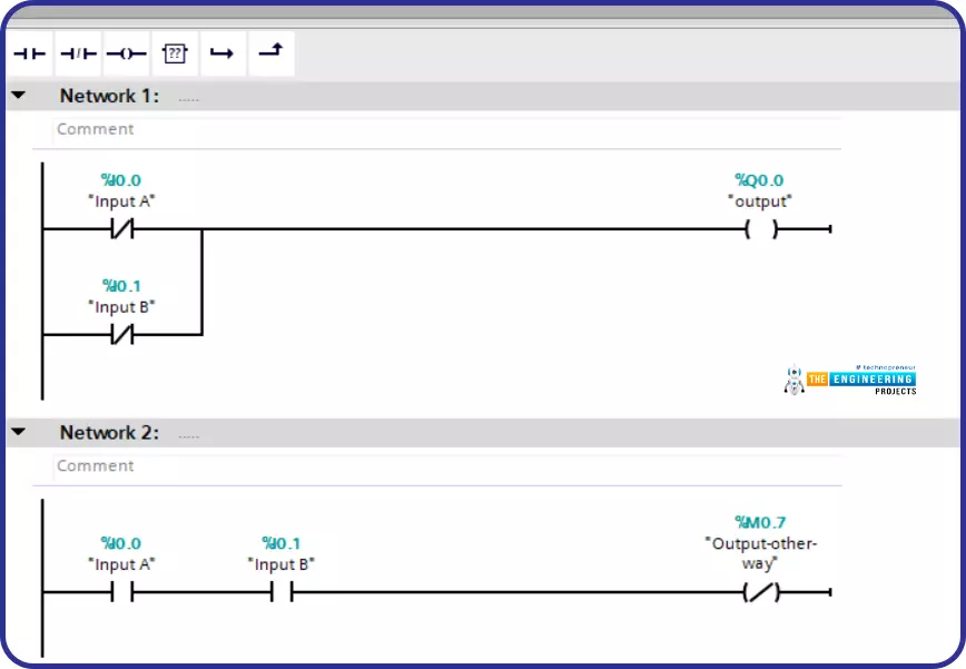
Hello friends! I hope you are all very well! I am so happy to meet you today to continue learning and practicing PLC ladder logic programming. In an earlier part, we already have gone through the very basic logic gates of “AND”. “OR”, and “NOT”. Today we are going to resume the simulation of logic gates. We have started and gone through simulating the basic logic gates which are “AND”, “OR”, and “NOT” as they are the most important basic logic gates by which we can form other logic gates. However, because the logic of large-scale projects is getting more and more complicating, a lot of time we have to use the other functions to do tasks faster. For example, we have shown in the logic gates article that, XOR can be used to compare two inputs and check if they are equal or not. On the other hand, someone may say, oh we can do XOR by using the basic three gates of “AND”, “OR”, and “NOT”. That’s correct. So why do we need to go learning other logic gates when we can implement them by using that three basic logic gates. Well! That is a very good question.

Working in ladder logic programs is getting further complicated especially for large-scale projects. So, it is very beneficial to know shortcuts for writing ladder logic simpler, more readable, and easier for others to develop. Using this variety of logic gates, enrich the logic and fluency of writing the logic in different situations. For example, using XOR logic is very common for comparing two inputs to decide if they are equal or different. Therefore, we found that it is crucial to go through all logic gates and do simulations for them all in this tutorial. for coherently we get the knowledge to use them fluently in ladder logic programming to solve different logical problems and scenarios. There are seven basic logic gates which are: “AND”, “OR”, “NOT”, “NAND”, “NOR”, “XOR”, and “XNOR”. We have gone through “AND”, “OR”, and “NOT” logic gates including simulation work. So let us go through the other four gates for learning and practicing all basic logic gates.

The "NAND" Logic Gate

The “NAND” logic gate is the invert of the “AND” gate like you invert the output of an “AND” logic gate as shown in Fig. 12. Table 5 lists all combinations of the inputs and the output of the “NAND” logic gate.

Fig. 12: NAND symbol

Table 5: the truth table of the “NAND” logic gate

Input A Input B Output
0 0 1
0 1 1
1 0 1
1 1 0
 

In addition, the timing diagram of a “NAND” logic gate is shown in fig. 13, it shows the output goes low when both of the inputs A and B are true which is the inverse of the “AND” logic gate. Also, Fig. 14 shows a ladder logic of a “NAND” logic.

Fig. 13: The timing diagram of the “NAND” logic gate

Fig. 14: Ladder logic sample of a “NAND” logic

NAND Logic in PLC simulator

The NAND logic gate can be considered as the invert of the “AND” logic gate. So as listed in table 1, the truth table of AND and NAND logic gates shows how the NAND gate is the reverse of the AND gate. Also, it shows the NAND gate should come out to your mind when you want the output always low except when both inputs A and B are high.

Table 1: the truth table of the AND versus NAND logic gate

The NAND gate can be implemented by connecting the negate of the output in series to the inputs A and B. Another way to implement NAND is by inverting both inputs and connecting them in parallel as shown in fig. 1. Rung 1 and rung 2 respectively.

Fig. 1: The NAND ladder logic in two ways


Let’s test our ladder logic in both methods. According to the truth table of NAND gate, we have four test cases. figure 2 shows the first test case when both inputs A and B are false. In this case, the output should be true as shown in fig. 1.

Fig. 2: NAND ladder logic when both inputs are false

figure 3 shows the second test case when inputs A goes true while B is false. In this case, the output should be true as shown in fig. 3.

Fig. 3: NAND ladder logic when input A is false and input B is true

Figure 4 shows the third test case when inputs B goes high while B is low. In this case, the output should be true as shown in fig. 4.

Fig. 4: NAND ladder logic when input A is true and input B is false

Figure 5 shows the last test case when both inputs A and B become high so the output goes false as shown in fig. 5.

Fig. 5: NAND ladder logic when both inputs are true

Thanks to performing the simulation of the NAND gate, we now can conclude that we should be looking for a NAND logic when we want to shut down an actuator i.e. motor whenever two inputs are in a true logical state simultaneously. For a practical example, when we have three pumps and we want to run them in the mode of two of three. There should be only two of the three pumps to run at any time. In that case scenario, the run condition of any motor can be a NAND of the status of the other two motors.

The “NOR” Logic Gate

The “NOR” logic gate receives two inputs and has one output. It is the same as the invert of the “OR” logic gate. Like you follow the output of an “OR” gate by a “NOT” logic gate. Fig. 15 shows the symbol of a “NOR” gate. In addition, the truth table is expressed in table 6. It shows the output becomes false only when one of the input A or input B or both goes high which is the reverse logic of the “OR” logic gate.

Fig. 15: The symbol of “NOR” gate

The “NOR” logic gate can be formed by connecting the “OR” logic gate to the inverter “NOT” logic gate. Or by inverting the inputs by using “NOT” logic gates and connecting them to the “AND” logic gate as shown in Fig. 16.

Fig. 16: structure of “NOR” logic gate

Table 6: the truth table of the “NOR” gate

Input A Input B Output
0 0 1
0 1 0
1 0 0
1 1 0
 

Figure 17 shows an example of a ladder program for implementing the “NOR” logic gate. It shows that the “NOR” gate can be implemented in ladder logic by connecting two contacts of type NC in series.

Fig. 17: A sample ladder for a “NOR” logic gate

On the other hand, the timing diagram of the “NOR” logic gate is depicted in Fig. 18. It shows the output is false as long as either input A or input B or both are true.

Fig. 18: The timing diagram of the “NOR” logic gate

NOR logic gate in PLC Simulator

This logic gate can be considered as the negate of OR as you can notice in the truth table as listed in table 2. You can now feel when we may need to use the NOR logic? Yes! Exactly you want it when you design for output which is all time off except when both inputs are false.

Table 2: the truth table of NOR versus OR

Input A Input B OR NOR
0 0 0 1
0 1 1 0
1 0 1 0
1 1 1 0
 

Figure 6 shows two ways to implement the NOR logic in ladder logic. To make that happen, we connect the invert of the two inputs in series to the output as shown in the top part of fig. 6. The other way is to connect the two inputs in parallel to form OR and then connect to negate the output as shown in the lower part of fig. 6.

Fig. 6: The ladder logic of NOR logic gate

Let’s practice simulation of the NOR gate, in fig. 7, the first test case is when both inputs are false, the output is true as shown in fig. 7.

Fig. 7: The Simulation of NOR ladder when both inputs are false

Figure 8 shows the second case when input A is true and input B is false, the output is false as shown in fig. 8.

Fig. 8: The Simulation of NOR ladder when input A is true and input B is false

Figure 9 shows the third test case when input B is true and input A is false, the output is false as shown in fig. 9.

Fig. 9: the Simulation of NOR ladder when input B is true and input A is false

Figure 10 shows the last test case of NOR ladder logic, it shows the output is false

Fig. 10: The Simulation of NOR ladder when both input A and B are true

One practical example of using the NOR logic is that, imagine friends we drive some machine with two motors. And it is required to have at least one of them or both are running all the time otherwise alarm should be energized. The NOR logic is the best to manage that alarm to get energized if and only if both motors are off.

The Exclusive OR "XOR" Logic Gate

Despite this logic gate having two inputs and one output like the “AND” and “OR” logic gates, this logic gate is a bit more complicated than the previous logic gates. Table 4 lists the truth table including all combinations of the inputs and the output. By noticing the truth table of the XOR logic gate, you can see the output becomes low when the two inputs are equal like both are high or both are low. But the output goes high when there is a difference in the state of the two inputs. Imagine my friend, how much this logic gate is very beneficial for comparing two signals.

Table 4: The truth table of XOR logic gate

Input A Input B Output
0 0 0
0 1 1
1 0 1
1 1 0
 

On the other hand, Figure 10 shows the symbol of the XOR logic gate and its schematic. See how the basic logic gates OR, AND, and NOT can be utilized to build the logic of XOR logic gate.

Fig. 10: The XOR logic gate symbol

Figure 11 shows a sample of a ladder logic program that implements XOR logic. In addition, it shows the timing diagram of the inputs and output, it shows the output goes high when there is a difference between the two inputs and becomes low when they are equal i.e. both are low or both are high.

Fig 11: Sample of the ladder logic for XOR logic and the timing diagram

XOR Logic Gate in PLC Simulator

The XOR is used to compare two signals if they are equal or different. Table 3 lists the truth table of the XOR. It shows that the output comes to true when inputs are different and becomes false when they are equal.

Table 3: The truth table of XOR logic

Figure 11 shows the construction of XOR ladder logic. It shows that it is composed of, two parallel branches and each branch is forming AND logic of the two inputs in the opposite logical state.

Fig. 11: The ladder logic of XOR

Figure 12, shows the simulation results of XOR when input A and B are false, the output is false.

Fig 12: Simulation of XOR ladder when both inputs are false

Figure 13, shows the simulation results of XOR when input A is true and input B is false, the output is true. Fig 13: The Simulation of XOR ladder when input A is false and input B is high

Figure 14, shows the simulation results of XOR when input B is true and input A is false, the output is true.

Fig 14: The Simulation of the XOR ladder when input B is true and input A is false.

Figure 15, shows the simulation results of XOR when input A is true and input B is true, the output is false.

Fig 15: The Simulation of XOR ladder when both inputs are true

In a conclusion, the XOR logic in simulation shows that the output is low whenever both inputs are equal and goes high when the inputs are different in the logical state. A very good practical example for utilizing the XOR logic is that imagine friends we have a motor that is energized by two different destinations, and it should be requested by only one at a time. So we can get the run signal from the XOR of the two input switches. So, the only case to run the motor is by requesting from one source.

The “XNOR” Logic Gate

This logic gate is the invert of the XOR gate. So it is equivalent to applying an inverter to the “XOR” logic gate. Table 7 lists the combination of its two inputs and its output. It shows clearly that, the output becomes true when inputs are equal i.e. both inputs are true or both are false.

Table 7: the truth table of the “XNOR” logic gate

Input A Input B Output
0 0 1
0 1 0
1 0 0
1 1 1

Fig. 20 shows the symbol of the “XNOR” logic gate, it shows clearly how it is the invert of the XOR logic gate. This logic gate is very useful to validate if two signals are equal or not.

Fig. 20: The symbol of the “XNOR” logic gate

On the other hand, Fig. 21 shows a sample ladder logic of an “XNOR” logic gate implementation. It shows that there are only two ways to have the output in the TRUE state which are by setting both inputs TRUE or set both FALSE.

Fig. 21: A sample ladder logic for “XNOR” logic

Fig. 22 depicts the timing diagram of the inputs and output of the “XNOR” logic gate and clearly shows the output goes high when both inputs have the same state.

Fig. 22: the timing diagram of the “XNOR” logic gate

XNOR Logic in PLC Simulator

The XNOR is the invert of the XOR and it is used to compare two input signals. Table 4 lists the cases of the truth table of XNOR logic. It shows the output goes high when both inputs are equal i.e. both are high or both of them are low.

Table 4: the truth table of XNOR logic

Figure 16 shows the construction of XNOR ladder logic. It shows that it is composed of, two parallel branches and each branch is forming AND logic of the two inputs in the same logical state.

Fig 16: XNOR ladder logic

Figure 17, shows the simulation results of XNOR when input A and B are equal i.e. both are false, the output is high.

Fig. 17: The Simulation of XNOR ladder when both inputs are false

Figure 18, shows the simulation results of XNOR when input A is true and input B is false i.e. they are different. So the output goes false.

Fig. 18: The Simulation of XNOR ladder when input A is false and input B is high

Figure 19, shows the simulation results of XNOR when input A is false and input B is true i.e. they are different. So the output goes false.

Fig. 19: The Simulation of the XNOR ladder when input B is true and input A is false.

In the last case when both inputs A and B are high as shown in Fig. 20, the output becomes true.

Fig. 20: The Simulation of XNOR ladder when both inputs are true

We can conclude that the XNOR is marked by the true status of its output whenever both inputs are equal and vice versa. One of the most common scenarios for the best practice of XNOR is the protection of the operator's hands in the cutting machine. In that machine, the command for running the knife driving motor is an XNOR of two switches on the left and right hand of the operator. In that way, it is guaranteed that to run the motor, the operator should use both hands at the same time.

What’s next

I am very pleased to see you up to this point of our tutorial, Now you are familiar with all logic gates and practiced their logic on the simulator. In addition, you can feel the importance of mastering all these logic gates to ease your programming and enrich your programming skills. In the next tutorial, we are going to go deeply through the edge signal including rising and falling edge. We are going to introduce the benefits of these edge signals and how they can be utilized in ladder logic programming to solve a lot of problems. So be ready for more learning and practice with simulation in ladder logic series.

ESP32 Hall Effect Sensor in Arduino IDE

Hello readers, I hope you all are doing great. Welcome to Section 5 of the ESP32 Programming Series. In this section, we are going to interface different Embedded Sensors with the ESP32 Microcontroller Board. ESP32 development board is featured with some inbuilt sensors(i.e. hall effect sensor, capacitive touch sensor) so, in the initial tutorials of this section, we will explore these built-in ESP32 sensors and in the later lectures, we will interface third-party sensors with the ESP32.

In today's lecture, we will discuss the working/operation of the ESP32 built-in Hall Effect Sensor. Hall Effect sensor is used to detect the variation in the magnetic field of its surroundings. So, let's first understand What's Hall Effect:

Where To Buy?
No.ComponentsDistributorLink To Buy
1ESP32AmazonBuy Now

What is the Hall Effect?

The Hall Effect phenomenon was first discovered by Edwin Hall in 1879. When current passes through a conductor, the electrons move in a straight line and thus the voltage difference across the conductor's surface remains zero, as shown in the below figure:

However, when a magnet is placed near the current-carrying conductor in a way that the direction of the magnetic field is perpendicular to the flow of current, the electrons get diverted and don't follow a straight line, which results in generating a small potential difference across the conductor's surface, as shown in the below figure:

This small potential difference generated because of magnetic field presence is called Hall Voltage. This magnetic field influence over the current-carrying conductor is termed the Hall Effect.

Hall Effect Sensor

A Hall Effect Sensor is a non-contact type embedded sensor, used to detect the presence & intensity of a magnetic field in its surroundings. Different third-party Hall Effect Sensors available in the market are shown in the below figure:

  • A normal Hall Effect Sensor Pinout consists of 3 Pins i.e.
  1. Vcc: Normally +5V, few +3.3V are also available.
  2. GND: We need to provide Ground here.
  3. OUT: The Output Pin to give the sensor's response.
  • When a perpendicular magnetic field is placed near a Hall-effect sensor, it changes the status of its Output Pin.
  • The analog Hall Effect Sensors can also detect the strength of the magnetic field i.e. greater the magnetic field greater will be the sensor's output or voltage deviation.

Applications of Hall Effect sensor

  • In an Automotive system, Hall Sensors are used to detect speed, distance, position etc.
  • Used in Proximity sensing.
  • Used in Current sensing.
  • Used in Anti-lock braking system.
  • Used in Internal combustion engines to assist with ignition timing.
  • To switch an electric circuit ON and OFF.

Hall Effect Sensor in ESP32

In ESP32, the Hall effect sensor is located inside the ESP-WROOM-32 metallic cover. As the Hall Effect sensor is a non-contact type, it doesn't have to be in contact with the magnet. We just need to place the magnet above this metallic sheet and the ESP32 Hall Effect sensor will detect it.

Programming ESP32 Hall Effect Sensor using Arduino IDE

To understand the working of the Hall sensor with ESP32, let's test the builtin ESP32 example:

  • You can find the code through File> Examples> ESP32 > Hall Sensor, as shown in the below figure:

Arduino IDE code

Here's the code for this ESP32 Hall Sensor example:

int val = 0;

void setup()
{
   Serial.begin (9600);
}

void loop() 
{
   val = hallRead();
   Serial.print ("sensor value = ");
   Serial.println (val);//to graph

   delay(100);
}

Code Description

The code is quite simple, where the hallRead() function is called to read the hall sensor value, store it into a variable and then print it on the Serial monitor. Finally added a small delay to get the next value. Let me explain the code line by line for the beginners:

Variables Declaration

  • The first step will be the declaration of an integer-type variable to store the hall sensor value. The initial value assigned to the variable is zero.
int val = 0;

Setup() Function

  • Inside the setup function, the only task is to initialize the serial port at a 9600 baud rate for serial communication.
void setup()
{
   Serial.begin (9600);
}

Loop() Function

  • Inside the loop function, we called a function ‘hallRead()’ to read the sensor value and store those readings into the variable ‘val’.
  • Printed the sensor readings on the serial monitor or serial plotter using serial.println() function.
  • A delay of 0.3 sec is added at the end.
void loop() 
{
   val = hallRead();
   Serial.print ("sensor value = ");
   Serial.println (val);//to graph

   delay(100);
}

ESP32 Hall Effect Sensor - Testing

  • After successfully uploading the code into ESP32, open the serial plotter or serial monitor to monitor the results.
  • Place a magnet near the ESP32 board.
  • The sensor reading will increase/decrease depending on the magnet pole(i.e. North or South Pole) facing the Hall sensor.
  • Now click on Tools > Serial Plotter to visually analyze the sensor's output.
  • The Serial Plotter of our project is shown in the below figure:
  • As you can see in the above figure, the sensor is giving negative output when facing the North Pole of the magnet.
  • In the case of a South Pole, the sensor's output is positive.
  • In the absence of a magnetic field, the sensor's output is almost 0.
  • The distance between the magnet and the Hall sensor decides the amount of potential difference generated.
  • The greater the distance between the two, the smaller the hall voltage or potential difference will be.
  • We have attached an image from the Arduino IDE serial monitor for your reference.

This concludes the tutorial. I hope you found this helpful, test it out and if feel any difficulty, let me know in the comments. In the next tutorial, we will have a look at another built-in sensor of ESP32 i.e. Capacitive Touch Sensor. Thanks for reading.

Car Parking System with Automatic Billing using Arduino

Hi Geeks, welcome to our new project. Our new project is one of the most common issues you’ve seen in your cities. In this project, we are going to make a car parking system with automatic billing. In the entire world, there are an estimated 1.4 billion cars on the road, which is absolutely great news if we are considering the development of the Automobile industry. But the most serious issue is that the number of cars exceeds the number of available parking places, resulting in traffic congestion. Damaged cars due to this lack of space, fewer parking locations, lack of parking signage, informal parking, and overcharging for parking are just a few of the issues.

People are still choosing manual parking methods, which have a number of drawbacks, such as searching for a vacant spot in a parking lot without knowing if the lot is full or not, resulting in time and fuel waste. Vehicle safety is also a concern that may be addressed. We've all been in a position when we've spent a long time looking for parking at a location just to discover that none is available. You would think that if you knew the slots were full, you would've ended up finding another parking spot.

Based on these scenarios, we came up with the idea of a Car Parking System with Automatic Billing which will also reduce manpower such as security, booth attendants, etc., required in parking lots. Everything in the modern day is automated, and with this project, we can automate this procedure using simple electronics components and Arduino. Let's get started.

Where To Buy?
No.ComponentsDistributorLink To Buy
1DS1307AmazonBuy Now
2Keypad 4x3AmazonBuy Now
3LCD 20x4AmazonBuy Now
4Arduino UnoAmazonBuy Now

Software to install:

Instead of using real components, we'll use the Proteus Simulation tool to design this project. It's also a good habit to experiment with simulations before attempting to build everything with real components. By simulating an issue that may develop when working on actual components, we may identify the problem and avoid any damage to our components.

Proteus is an interesting software that lets you model and build electronics circuits. Despite having a huge library of electronics components, Proteus software lacks pre-installed modules such as Arduino boards, Ultrasonic sensors, RTC modules, LCD modules, and so on.

Now, we’ll start installing the libraries, which is needed for our project:

By clicking the button below, you can download the entire project, including Proteus Simulation and Arduino Code.

Project Overview:

These are required components for Accident Detection, which are as follows:

  • Arduino Uno: Arduino Uno is a development board from the Arduino family, which is the main component of this project and acts as the brain. The Microcontroller i.e., Arduino is responsible for the decisions that are going to be processed in the project.
  • 20X4 LCD display: It is used to display the information regarding parking slots and shows the amount that has to be paid by the driver at the Check out time from the parking lot.
  • Ultrasonic Sensor: It is used to calculate the distance from the car to the entry gate and detects that a car has reached near the gate.
  • RTC Module: Real-Time Clock Module is used to calculate the time and plays a key role in determining the total amount for the parking slot.

Components Needed:

  1. Arduino Uno
  2. LCD Module
  3. Ultrasonic Sensor
  4. Keypad 3x4
  5. LED’s
  6. RTC Module

Components Details

Arduino Uno:

  • Any Arduino development board can be used in this project, however, we'll be using Arduino UNO development boards. The Arduino UNO is a programmable, open-source microcontroller board from the Arduino series.
  • It contains an ATMega328P microcontroller from Atmel, which has an 8-bit RISC processing core and 32 KB of flash memory.
  • The Arduino UNO includes 14 digital I/O pins i.e., D0 - D13, with a resolution of 10 bits, including 6 PWM pins and 6 analog I/O pins (0-1024) i.e., A0 - A5.
  • Only one hardware UART peripheral pin, one I2C peripheral pin, and one SPI peripheral pin are available on the Arduino UNO (however we can use other pins for UART communication using the SoftwareSerial package in Arduino).
  • The Arduino UNO can be powered from a voltage range of 7 to 12 volts, the voltage regulator embedded inside the board will reduce the excess voltage. however, not more than 9 volts is suggested since it might harm the Arduino board.
  • A USB-B cable (the same cable that we used to upload the sketch to Arduino UNO), a DC power jack, and the Vin pin on the board may all be used to power Arduino UNO.
  • Using the Arduino IDE Software, the sketch is written and uploaded to the Arduino UNO. It is completely free, simple to comprehend, and easy to combine with a variety of electronic components.

LCD Module:

In this project, an LCD display is used to present the information to the user.
  • LCD stands for Liquid Crystal Display, and it is a type of display that is made using Liquid Crystal technology.
  • LCDs come in a variety of sizes; in this project, we utilized a 20X4 size.
  • The 20X4 indicates that it can show 80 ASCII characters at once.
  • The LCD has 16 pins. In which the necessary pins are connected in the circuit.
  • It contains eight data pins, one Read/Write select pin, one Register mode pin, one Enable pin, two backlight pins, two power supply pins, and one contrast control pin.
  • In the LCD, there are primarily two types of registers: Command Register and Data Register.
  • When the RS(Register Select) pin is set to logic high, the data register mode is selected, and when it is set to logic low, the command register mode is selected.

The RS pin will be set to logic high to display the data on the LCD.

Ultrasonic Sensor (HR-SR04):

  • The HC-SR04 ultrasonic sensor employs SONAR to estimate the distance of an object.
  • The ultrasonic sensor sends out a signal wave that has a frequency of about 40 kHz, with a high pitch that humans are unable to hear.
  • From 2 cm to 400 cm (1" to 13 feet), it provides the detection of objects with high accuracy and the pulse will not be disturbed by sunlight or any climate conditions.
  • It consists of four pins, Trig, Echo, VCC, and GND.
  • The operating voltage of an Ultrasonic sensor is 5V. We can connect the VCC pin of the sensor with 5V output in Arduino and the sensor will work perfectly.
  • Ultrasonic sensors work on the principle of sound wave reflection.
  • The trig pin works as an ultrasound transmitter which emits the high frequency sound waves in pulses. And the echo pin works as an ultrasound receiver. It receives the reflected ultrasonic waves which are bounced back from the object.
  • We calculate the distance from the object and the sensor by measuring the time taken between the transmission and the reception of the signal.
  • To measure the distance of sound traveled from trig to echo,

Distance = (Time x SpeedOfSound) / 2.

Speed of Sound: 340 meters per second i.e., 0.034
  • The easiest way to calculate the distance in cm is using this formula,

Distance in Centimeters = (( Time taken by pulse signal (in microseconds) / 2) / 29)

Keypad 3x4:

  • A keypad button is used for user input.
  • The keypad's buttons are arranged as a matrix of 3x4. Which means it has four rows and three columns.
  • They work on the principle of membrane keypads. They are very flexible and feel like a push button.
  • The switch between a column and a row trace is closed when a button is pressed, allowing current to pass between a column pin and a row pin.
  • A copper padding and line beneath the pad connects each switch in a row to the other switches in the row.

RTC Module (DS1307):

  • The DS1307 IC is a low-cost, high-accuracy RTC that uses the I2C protocol as an interface.
  • The DS1307 features a backup battery mounted on the rear of the module to maintain track of time even if the main power supply is disconnected.
  • When necessary, the chip shifts between the primary and backup power sources.
  • The RTC records information such as seconds, minutes, hours, days, dates, months, and years.
  • This module includes a Reference clock, programmable Square wave output(SQW), SCL, SDA, VCC, and GND.
  • Automatic Power-Fail Detect and Switch Circuitry
  • Low Power Operation Extends Battery-Backup Run Time.
  • The RTC module works on operating voltage 5V.

Proteus Simulation of Car Parking System:

Now, it’s time to start the design of the Proteus Simulation of our Car parking system

  • Before you begin designing, make sure Proteus is installed on your computer and that you have downloaded all of the necessary libraries.
  • We'll need Arduino libraries and LCD modules for this project. Make sure you've read the section on using libraries in Proteus software.
  • Let's begin by creating a new project, and importing all of the required components, and placing them within the working area.
  • Select all of the components from the Proteus component library that we'll require.

Circuit Diagram and Working:

After importing all required components to the workplace, let’s move to connecting them.

  • Starting with the connection of LEDs, we are using digital pins 2,3,4,5,6 for LEDs. Connect the positive side of the LEDs to the Arduino UNO board.
  • After that, connect the Ultrasonic sensor module’s Trig pin and Echo pin to digital pin 8 and 7 respectively, Vcc to 5v volt power and GND to Ground.
  • In the simulation. it will not be possible to change the distance from the Ultrasonic sensor so for that we have connected a potentiometer with the test pin of the module.
  • Now start the connection of the Keypad, as this is a 3x4 keypad so it will use 3 pins for columns and 4 pins for rows.
  • As there are limited digital pins on Arduino UNO, we have to use the analog pins of Arduino UNO as digital pins.
  • Now let’s connect the row pins A, B, C, D with A0, A1, A2, A3 respectively and column pins 1, 2, 3 with digital pins 9, 10, 11 respectively. And we have to connect the pins in an exact manner.
  • RTC module uses the I2C protocol, so we will connect SDA and SCL pins to Arduino UNO’s SDA (A4) and SCL (A5) pins respectively. Vcc with 5v power supply and Gnd with the ground.
  • As there are no pins left for connecting the LCD module therefore we will use an I2C GPIO expander for connecting the LCD module.
  • Connect the SDA and SCL pins of GPIO expander with the SDA and SCL pins of Arduino UNO and we have to set the slave address of GPIO expander, for that we will connect the A0, A1, A2 pins with ground, that will set the I2C slave address to 0x20.

Now we have done the circuit, it’s time to move to the coding side of this project.

Arduino code for the accident detection:

  • We must add relevant libraries, which operate as header files in programming languages before we begin writing the code.
  • So, if the necessary libraries aren't already installed in the Arduino IDE, we'll need to download them first.
  • We can install Arduino libraries by going to 'Sketch > Include Library > Manage Library' in the Arduino IDE. In the library manager, we can now search for our essential libraries. The libraries can also be installed via zip files.
  • We can download the libraries from the above instruction, but if they are not available, we can use the following links to download the zip files of libraries.
  • Here we used “Wire.h” to enable I2C communication and it is pre-installed.
  • “LiquidCrystal_I2C.h” is used for the LCD.
  • “Keypad.h” is used for the integration of the keypad module.
  • “RTClib.h” is the library for RTC modules.
  • Let’s declare the pins for modules. We mainly use two pins i.e. Trig and Echo for the object detection and distance calculation. Here we have connected the Echo pin to D7 and Trig pin to D8 in Arduino Uno and an array for storing the pins for LEDs as D2, D3, D4, D5, D6. Two arrays for storing the pins for keypads such as rowPins for A0, A1, A2, A3 pins and colPins for D9, D10, D11.
  • Now, Let’s declare configuration related variables for the keypad. Here we are declaring variables to store the number for Rows and Columns. We will use a 2D char array named ‘hexaKeys’ for storing the symbols of keypad.
  • Now declare some general variables for storing the values for ultrasonic sensors, charge, total charged amount, check-in time and check-out time of vehicles.
 
  • Now, Let’s declare the objects of the modules.
 
  • The “customkeypad” is initializing an instance of class NewKeypad. The statement is going to map these symbols with the pins we have declared to connect with Arduino. Hence, it will map according to the row and column pins.
  • Next, we are initializing the LCD display with an I2C serial interface and setting the address to 0x20 Hex.
  • And we are declaring an object named ‘rtc’ for the “RTC_DS1307” module.

Void Setup():

  • The void setup() is an important function in the sketch that will execute only once in the whole program. The input, output, and other serial communication initializations are done inside the void setup. Let’s write the void setup sketch now.
  • In this setup function, firstly we have enabled the serial communication with “Serial.begin” with the default baud rate of 9600.
  • Next, we are initializing the LCD and turning on the backlight of the LCD.
  • We have already declared the Trig and Echo pins before in the declaration part, and now we are going to set them up as output and input pins respectively.
  • There may be a doubt why we have declared a Trig as output and Echo as input. That is because the Trig pin will generate the ultrasonic wave pulses and the Echo pin will work as a receiver for reflected waves.
  • We are using five led’s for the five slots in the parking lot and to make the logic simpler, declare the led pins as output mode.
  • Now, we are printing a line in the serial monitor and LCD. We are using the cursor function and printing “Made by” in the first row and “Tushar Gupta” in the second row. (0,0) is representing (column, row) in the LCD.
  • After printing the line, clear the LCD screen.
  • Now, we are trying to initialize the RTC module and if the RTC is not found, it will print that “Couldn’t find RTC”. and halt the further processing of code.

  • After successful initialization of the RTC module we will know if the RTC module is running already , if yes then we don’t have to set the time explicitly otherwise we have to .
  • We will use a “dist()” function to calculate the distance using the formula mentioned in component details.
  • For the calculation of distance, we will generate the pulses using the Trig pin.
  • To generate the pulses , switch the TRIGpin to LOW for 4 microseconds and then HIGH for 10 microseconds then again LOW .
  • By using ‘pulseIn’ we can calculate the time duration the wave has taken to travel back from the object.
  • “ distance = duration*(0.034/2); ” and here 0.034 is the speed of sound and with this formula, we can calculate the distance in cm and set the threshold values.
  • “pulseIn” takes two arguments, first pin number and second logical state. This will read the pin for logic HIGH and return the time period in which that pin was at a HIGH state.
  • For more knowledge of “pulseIN “ refer to this link: pulseIN function

Void loop():

  • It is the next most important function of Arduino code/ sketch. The “void loop()” will run after the execution of “void setup()”.
  • We'll write the code required to run in a continuous loop in this part. So here we'll write our main application code.
  • Here, we are going to first discuss the Automatic billing part near the gate in our parking system.
  • In the loop function, the Date and Time of that current time are set by “rtc.now”, and the user will enter his slot number in the keypad when he/she is exiting from the slot.
  • The user will click the allocated slot number on the keypad and we are collecting that in the “customkey” variable using the “getkey” function.
  • The serial monitor will print the custom key entered by the user. Then we will check the slot status by “digitalRead (led[i])”.
  • If the led status is HIGH which means the slot was occupied now we will generate the bill for that slot and display that amount on the LCD display for1 second after clear the LCD and set that slot LED to LOW state.
  • The next step we are going to do is to calculate the total amount according to his vehicle staying inside the parking lot. And for that, we can do the simple calculation that is “amount = charge*(gotime [i] - cometime [i]) ;”.
  • We have already declared the charge amount in the above sections of the program. The charge will be multiplied by “go time - come time”, which is the total time the vehicle stayed inside the lot. And the multiplied result of stay time and charge is the final amount the driver has to pay for his parking slot.
  • Now, the driver can pay the amount and exit through the gate. Here, after a second delay, we are clearing the LCD display.
  • “What if the driver pressed any wrong key which has a free slot?” That might be the question in your mind. Well, we can cover that condition with an else statement, where we can print “The slot is already empty” on the LCD and let the driver know that he has entered the wrong key in the keypad near the exit gate.
  • Till now, we have seen the Automatic billing logic near the exit gate. But let’s see what is the slot allocation process at the entry gate.
  • As we have already calculated the distance with the ultrasonic sensor using the “dist()” function, we can set the distance limit to 100cm before the gate, and when a car reaches the entry gate the allocation of the slot will be started.
  • The “for loop” here will see what are the slots showing Low/empty in the parking and allocate that empty one to the car by printing “Park your car at ” and “Slot i” in the LCD.
  • As this slot was allocated, we have to write this LED as High which indicates the slot is not empty. This is the reason where the slot led is high at the exit gate when the user pressed his slot number in the keypad. We are turning on the LED when we are allocating the slot to a car.
  • Now we also have to collect the “come time” by the RTC module for further calculation at the end or near the exit gate.
  • We are implementing an if statement where the all LEDs are high, which means all the slots are filled, the LCD should print (“No more slots”) and inform the driver and clear the LCD screen.

Results / Working:

We have completed the Proteus simulation circuit and Arduino code for the Car Parking project. And it is ready for testing.

  • Before going to start the simulation, we have to add the hex file of our application code in the Arduino UNO module in Proteus and a hex code for the ultrasonic sensor also.
  • To add the hex file, click on the Arduino UNO and a new window will open then click on the Program files, there we will browse to our hex file.
  • In the same way, we can add a hex file for the ultrasonic sensor.
  • Now start the simulation, on the first boot of the circuit, LCD will display the welcome message and the same message will be displayed in the serial terminal also
  • Just for debugging purposes, we are continuously printing the ultrasonic sensor values.
  • In the simulation to change the distance between the vehicle and ultrasonic sensor we have used a potentiometer. Now change the value on the potentiometer.

As we can see that for 50% value on the pot ultrasonic sensor value is near to 500 cm and for 77% value on the pot ultrasonic sensor value is near to 850 cm.

  • Let's test the condition when the vehicle approaches the sensor, to satisfy that condition the object must be at a distance of less than 100 cm. For that, we have to change the pot value. Set the pot value near to 10 %.
  • After that LCD will display a message if that spot is vacant like “Park your car at Slot 1” and LED for the same location will glow.
  • To take the bill for any location press the keypad for that location number let’s suppose here the location is 1 so we will click on ‘1’
  • After that, it will generate the bill with the total charged amount and the LED for that location will be turned off.
  • In case if we click any slot button which is already vacant then LCD will display the message for the slot is vacant.

Here it is not visible which button on the keypad has clicked but suppose we have clicked ‘1’ and if that location is vacant then it will display that message.

  • Let’s take another case when we want to park another car. Now slot 1 is already busy so we will park at slot 2.
  • This time when the sensor value changes less than 100 cm, then the LCD display will show “Park your car at slot 2” because slot 1 is preoccupied.
  • In the image, we can see that both LEDs are glowing as both slots are occupied now.
  • For billing, we will click the button on the keypad for the respective slot.
  • Let’s take a case when all slots are occupied. Here we can see all slot LEDs are glowing.
  • Now we will try to park another car. Then LCD will display ‘no more slot’ as there is no vacant slot available at parking.

I hope you have a good understanding of how our Car parking system project works and that you have liked it. Although it’s a tough nut to crack in the first read, I strongly recommend you to read the logic part twice for better understanding. I believe we have covered almost everything, please let us know if you have any questions or suggestions in the comments section.

Thank you very much for reading this project. All the best for your projects!

Syed Zain Nasir

I am Syed Zain Nasir, the founder of <a href=https://www.TheEngineeringProjects.com/>The Engineering Projects</a> (TEP). I am a programmer since 2009 before that I just search things, make small projects and now I am sharing my knowledge through this platform.I also work as a freelancer and did many projects related to programming and electrical circuitry. <a href=https://plus.google.com/+SyedZainNasir/>My Google Profile+</a>

Share
Published by
Syed Zain Nasir