What are the business applications of 3D Printing?

Although 3D printing feels like a relatively new development, there are lots of promising projects underway. A scheme to build 46 eco-homes has been approved in the UK’s first 3D printed development , for example, and the same is happening in Australia to provide housing for remote indigenous communities in rural areas

But how can 3D printing be applied in business? Here’s a breakdown on how it can be used and the opportunities it creates.

What is 3D printing?

3D printing refers to technology that can form materials using computer designs. The earliest signs of 3D printing came about in 1981. Dr. Hideo Kodama created a rapid prototyping machine that built solid parts using a resin and a layer-by-layer system.

Using a bottom-up technique, the material is layered until a tangible item is created. We are still in very early days when it comes to 3D printing, but engineers are optimistic about how it can be applied on a large scale across industries. There’s great potential for using 3D printing in manufacturing and home building. 

How does 3D printing work?

3D printing begins with a design stage. This is the 3D modelling stage where you can uncover the best path to follow to get the most out of the design, such as the materials used. You will also be able to use this information to determine the cost and speed of your project, adjusting where necessary.

3D printing equipment is powered by a system of control cables such as those from RS to facilitate autonomous 3D printing applications. Data connections are also used to transmit the design to printing equipment.

Applications

3D printing is commonly used for prototyping ahead of launching major manufacturing projects. It allows product designers to get a life-size glimpse at the proposed product, enabling them to identify any faults or improvements before going ahead with more expensive resources and materials. While 3D printing can be done to a large scale, it can be done to a much smaller scale too to create smaller, cost-effective prototype models.

Design processes

The attention that is given to the design process and modelling stage means companies can analyse the production method used to create the desired output. Sometimes there will be limitations such as the fact that 3D printing can only work when adding layers on top of one another, which means features like overhangs can’t be catered towards in a simple manner. Regardless, 3D printing can still cater to things that traditional manufacturing can’t.

Manufacturing

3D printing can be used to minimise demand on time and manpower. It can be used to tackle more intricate tasks at a larger scale. Aerospace was one of the first industries to utilise this, as well as biomedical and mechanical engineering. In some cases, conventional manufacturing simply can’t replicate the detail at such a large scale.

PLC Troubleshooting and Online Debugging

Hi Everyone! How are you doing, my friends? Today I bring a crucial topic for PLC programmers, technicians and engineers. We have been working together for a long time using ladder logic programming. We have completed together dozens of projects from real life and industry. One day I was thinking about what we have done in this series of ladder logic programming, and I came across that I missed talking about one essential topic ever. You know what? It’s the PLC troubleshooting and online debugging! After writing a ladder logic program for the project, you can imagine it should operate from the download moment 24/7. As usual, any system goes faulty one day. So we need to go through this matter, showing you how to find our PLC faults, troubleshoot, and go online with the PLC to figure out the cause of the problem. Is it in the program logic? Or inputs and outputs? The hardware has an issue, i.e. battery has died, and the program has gone. For those of you who do not know the meaning of the expression going online with the CPU, do not worry, my friends, as we will show you the operation of the PLC.

What’s after the first program download?

That is such an excellent question to open our tutorial by saying that dealing with PLC has mainly three modes of operations: program mode, in which we are allowed to download from PC to PLC, remote mode, in which we are permitted to download and upload to and from PLC, and the run mode that allows us to go online for monitoring and troubleshooting. So Folks, assume we have just completed the programming of the project. Then we tested the logic and downloaded the program to PLC. So what if a fault occurred, as shown in figure 1, and the operator called you for support? That’s what we are going to discuss in this tutorial trying to transfer our experience to you, helping you to get familiar with troubleshooting PLC, and doing live debugging to your program while it is running on the PLC and all IOs connected to the actual device, including sensors and actuators. So let’s get to the tutorial.

Connecting to PLC

First, you bring the PLC programming cable and plug it from PC into PLC. The type of PLC cable depends on the plc type and model. That information you can find in the PLC manual or google it easily. After plugging the PLC cable from PLC into PC, you open the RSLINX software and create a connection using the appropriate driver. The next step is selecting the CPU to see many options to go with one of them. For example, you will see the “download” option used to move the program from PC to PLC; there is also an “upload” option used to get a copy from PLC to PC. And “GO-ONLINE,” which you use to debug the program while running on the PLC. You also need to know, my friends there are many operating modes of the PLC. The program mode allows you to change and modify the program, but the program is not running in that mode of operation. The run mode of operation is also one option to let the program run, and there is no way to do modifications in that mode. The last mode of operation is the remote mode which allows you to make changes and clear the faults, and the program runs simultaneously.     

Faulty PLC

Once you have tried to connect to the CPU, you will see what Figure 2 depicts below. You can notice, everyone, the status in is red “faulted,” and that fault will not allow the program to run. Now you need to do two things. The first is to go into the vault to see what it is and the cause of the fault to find a way to fix it. Second, after setting the fault, you will need to clear the fault. And ultimately, you will change to run mode.

So now, my friends, how to see the fault description to know the reason behind it? It is straightforward, as you can see in figure 3. You go to the fault and right-click to see a popup menu appear. The popup menu has a couple of options like go to error or clear the fault and other options like go online, download, and upload. Now, why not choose to clearing the fault? That might work if the reason behind the fault has gone. But it won’t as long as the fault is still there. If you try, it wbe incorrectrect once you try to move to remote or run mode. By the way, you can clear the error in the program mode only.

Exploring the Fault

Figure 4 shows how to go to the fault to get to know some information about the fault, like which routine in which the fault took place, the precise description and reason for the fault, and the status bits to show you the statuses of PLC. Figure 4 shows the window of the status bits. One tab is the “errors” tab which shows the details about the fault. Now you can see that guy clearly says there is an issue in the expansion module, so you can check the modules and fix the problem, and then you can go ahead clearing the error, as we will show you in the next section.

Clearing the Fault

Now everyone, after checking the fault reason and getting rid of that issue, it is time to clear the fault and return the CPU to regular operation by switching it back to run mode. Remember, if the fault causes are not eradicated correctly, the fault will return once you try to switch to remote or ryn mode. Figure 5 shows how to clear the fault by right click on the fault highlighted in red and choosing “clear fault.” Now let’s see what happens.

Figure 6 shows a message confirming to clear the fault because going with that will remove the saved information about the fault.

Figure 7 shows that the fault has been successfully cleared, and the program switched to remote program mode meaning the CPU is removed from the fault, but the program still is not running and need to switch to run mode. Remember, my friends, up to this point, we were curious if the fault reason had cured correctly until the CPU switched successfully to run mode.

Figure 8 shows the CPU has switched to run mode in green! That means the errors have cleared, and the causes have gone. Now we need to move on to showing you how to do debugging by going online with your program that is running on the PLC. So let’s see that together, folks.

Connecting and going online

Figure 9 shows the direct step to connect to the PLC by clicking the comms menu and selecting your PLC guy.

Figure 10 shows the connection has been established, and the remote running green appears on the top left, as you can see, my friends.

Figure 11 shows how to go online by clicking on the menu at the top left corner, as shown below, and you will see a popup menu that comes out showing their options: Download, Upload, and GO Online options. Choose the last to complete the online going procedure. So now you are connected and online with the PLC, meaning you can monitor all the parameters and values and see the IO’s statuses.

What’s next???

Thanks, my friends, for following up with me in this tutorial I see it’s essential for you all to practice because I can not imagine a PLc programmer who does not know such practice. Next time will bring a new project from the factory to continue learning and practice together the PLC ladder logic programming. So please stay safe and be ready to meet soon with a new tutorial. 

4-Floor Elevator Project with PLC Ladder Logic (Part 2)

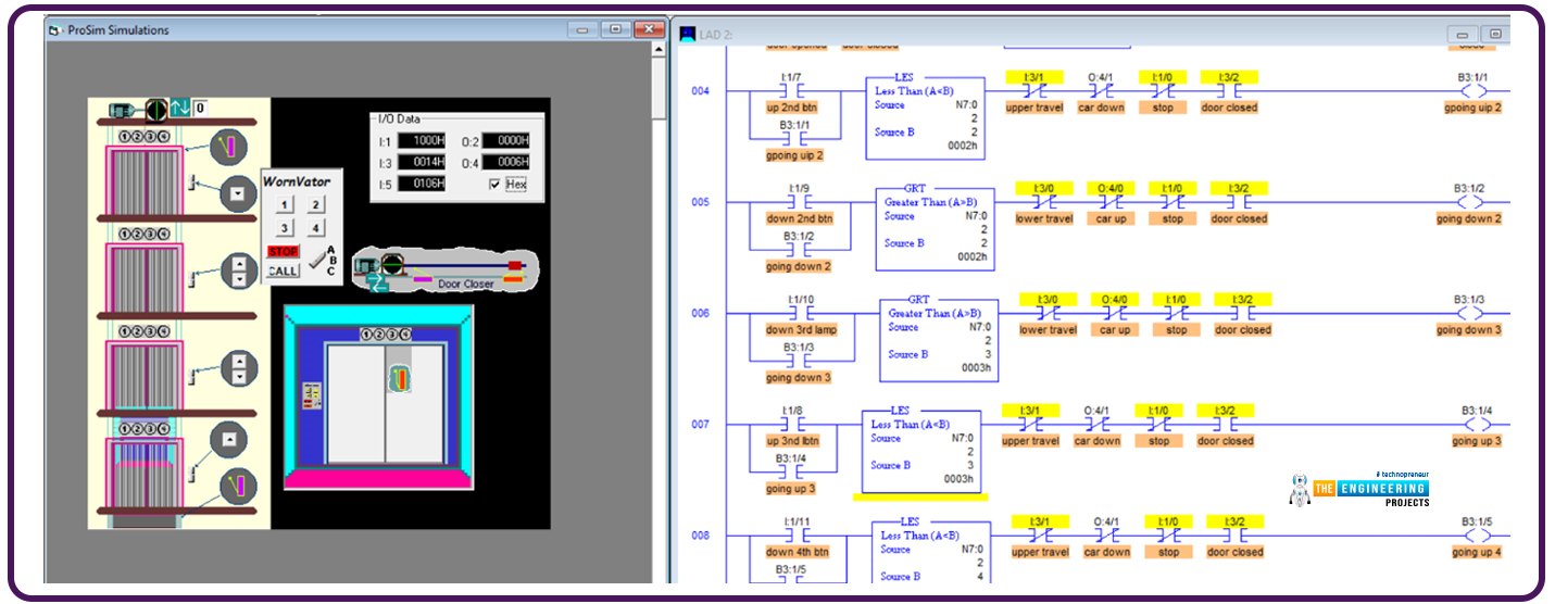
Hi, my friends and welcome back. I am happy to meet you again with a new tutorial of our PLC ladder logic programming series tutorials. Today we will complete what we started the last tutorial on the Elevator control project. We have a bunch of duties to complete together today. So let’s save time and jump into work immediately.

Project description:

Figure one shows the details that might help me describe the project between our hands. We have an elevator car that travels up and down and can stop on one of four floors based on the passengers’ requests. We have 6 push buttons on the wall next to the elevator door that can send requests to call the elevator. In addition, there is a control panel inside the elevator cabinet in which there are push buttons to request stations to reach floors 1, 2, 3, or 4. So now we are requested to manage all the scenarios and all requests received from inside and outside the elevator considering the priority of these requests to save energy and time management for the elevator traveling route. In the next section, the detailed requirements are listed.

The project requirements

The elevator should save all requests from the time they are requested until they are processed and cleared from the to-do list. 

The elevator should prioritize the requests in their direction of movement. For example, while he goes down, the requests for places located below his position will be given priority to do first. Similarly, when he goes up, the requests above the position where he is will be given priority. In that we, the waiting time will be reduced, and the energy and overall travelling distance will also be minimized. Because we have a lot to present in this significant project, let’s move on directly to the design and the ladder logic program that handles these requirements.

The design and logic of Elevator System

As usual, we are going to apply the divide-and-conquer rule. So the project will be divided into subtasks, and each task will be managed by one subroutine all subroutines are called in the main routine in sequence. Figure 2 shows the program structure which is composed of 5 subroutines. In the first routine, all initializations are called to be executed. So what’s in these subroutines? That is what we are going to show you below. So please follow up, my friends.

Figure 1 shows the ladder logic code of the first subroutine that initializes the work to start with the first floor as the initial position and going up as the initial moving direction and activate the action of performing the subsequent request or waiting for an incoming one.

The next subroutine is the heart of the logic, as it saves the requests and energizes the light indicators of the requested doors. Figure 3 shows a portion of the routine’s ladder logic code. As you notice, my friends, the first line is to tell the compiler that this is the start of the subroutine. The rung number 1 check if the request push button of the first floor inside the elevator’s car has been pressed and the elevator is not on the first floor; it will light the button lamp to show there is one request in the queue until the time comes to perform that request then the light will be turned off as we will demonstrate to you, guys. The next rungs, rungs number 2, 3, and 4, do the same for the corresponding keys inside the elevator’s car. If a push button is pressed, and its requested floor is not the current floor where the elevator is, then the corresponding lamp indicator is lighted, showing the request is saved in the queue, and when it is processed, the lamp indicator will be turned off. Now, moving on in the code, rung number 5 handles the outdoor request from pressing the first floor up push button. It simply checks the floor location. If it is not on the first floor, it lights; the lamp indicator of that push button shows that the request is in progress and will be turned off once it is processed. The following rungs do similarly the same function. But notice we have one push button for floors 1 and 4 while there are 2 push buttons for floors 2 and 3. So there are two rungs for handling the up and down direction requests.

One remaining thing for this subroutine is that the last rung confirms that when no requests are there so, the light on the first floor is turned on, showing that the elevator is on the first floor. Now my friends, let’s move to the next subroutine.

The next subroutine is called “track the vertical travel.” As you see, guys, the code checks in rung number 1 if the elevator is on the first floor, then it lit the first-floor light indicator and unlatched or de-energized the previous floor light, which is on the second floor and stops and opens the door. Now, when it reaches the second floor, indicated by the I:5 encoder, it lit the second floor and de-energized the lights of the next floors up and down, which are the first and third floors. Also, it checks if the second floor is being requested or in the queue list, then it stops the elevator and opens the door for getting or charging people who requested the second floor.

Figure 7 shows the ladder logic code of the second and last part of this routine; rung number 3, for example, checks if the elevator has reached the third floor; in this case, it lit the third-floor lamp indicator and turned off the next floors’ lamp indicators, i.e. floor 2 when it moves up from floor 2 to floor 3, or floor 4 when it goes down from floor 4 to floor 3. Also, if it goes down and the GO-Down request of the third floor is pressed, meaning there is a request in the queue, then it stops the elevator and opens the door for charging or discharging people who target the third floor. But, if it is going down and the Go-down, it stops the elevator and opens the door for charging or discharging the people.  And the last rung, number 4, handles the 4th-floor requests. If it is on the 4th floor, it just lights the light indicator on the 4th  floor and turns the light on the 3rd floor.

Now, my friends, the next routine is called “stop and open,” that handles opening the door at each destination. Figure 8 shows the logic; in rung number 1, if the door is not open for 2 seconds, then it is open the door, gives some time and then performs the subsequent request. When the door is opened, the request for the first floor is cleared. When it reaches floor number 2, and the door opens, if it goes up, clear the floor lightly and push the button to request the second floor, similarly, for the third and fourth floors.

Figure 9 shows the ladder logic code of the routine that decides which door will be bypassed and closing the door and go. It is called “ Do next or wait.” You can see, guys, it easily compares the moving direction and the requests in the queue based on the light status of the push buttons of all floors. Then bypass and resume with the door closed or wait and open the door for charging or discharging people.

Figure 10 shows the routine for closing the door at destinations. The routine is called “close door and move.” It simply checks if the door is closed and going up is requested, then lunch the move up the direction. But, if it is requested to move down, then latch the motor moving down. If no requests are moving up or down, enable the between-floors status. Now, my friends, we have explored all subroutines, and the time to test our logic and ladder logic program and subroutines has come. So let’s see if it is correct or needs some amendments.

Testing the ladder logic code

Figure 11 shows the initial state of the program while the elevator stops at the first floor, and the light indicators show the light of the first floor is lit, as you can see, my friends. Now let us command the push buttons requesting many requests to test.

From the initial position where the elevator is on the first floor, figure 12 shows the elevator has been requested as follows: on the second floor, it is requested to move up. On the third floor, it is requested to move down. On the fourth floor, it is requested to move down.

According to the requests and the sequences, it starts the journey from the first floor and stops at the second floor, as shown in figure 12.

Continuing his journey, he bypasses the third floor because it needs to go down. Show it gives priority to the request on the 4th floor, which is in his moving direction, as shown in figure 13.

Now, after reaching the most up, it changes direction and goes down to reach the third floor, which is the last request, as shown in figure 14. Notice, my friends, every time it reaches one requested place, it clears the light of the belonging request.

What’s next???

Clearly, the test successfully showed one scenario with all the test cases of moving, stopping, and bypassing. Thank you, friends, for following up on these points, and I hope you have enjoyed the project we have done together in this tutorial. Also, I promise the next tutorial will come with a new project from real life and learn more and enjoy practicing ladder logic programing together. So stay safe and be ready for our next tutorial.

Four floors Elevator using ladder logic programming

Hello, my friends and welcome back with one new tutorial of our ladder logic programming series. Today I am bringing one exciting project which you can see everywhere, in your home, work, and public places, which is an elevator. We will design a solution using plc ladder logic programming, which drives the elevator. Our elevator is composed of 4 floors and has all capabilities of large-scale elevators. So let’s get started and save time and jump into our tutorial.

Elevator Project

As you can see, Everyone figure 1 depicts the complete scene of the project and tells that the elevator we will manage has four floors to visit. On the first floor, there is only one outer request to call the car from any floor above, i.e. from floor 2, floor 3, or floor 4. While on the second floor, there are two request buttons to get the car from up or down floors and the same for floor 3. But floor 4, the last floor, has one request button to bring the elevator from the below floors, i.e. floors 1, 2, or 3. Also, the figure shows the request buttons inside the elevator car. There are request buttons for each floor, one-stop button, and one call button for emergencies. Now let’s move on to the inputs and outputs we will use in our logic:

Project inputs and outputs (IOs)

Smartly, we wrote one rung ladder logic as shown in figure 2, which does nothing but show the IOs the project has and names each IO with the descriptive name. We typically do such a rung for listing all IOs in one place to see the status of all IOs with one look. So what IOs do we have in this project? Well! You can see the request push button on the first floor from right to left and connected to input I:1/6. Also, the lamp indicator shows that the request is in progress. That indicator is connected to output O:2/6. In the second column, you can notice my friend’s two request push buttons connected to digital inputs I:1/9 and I:1/7. Also, for each request push button, there is an indicator lamp. The indicators of up and down requests for the second floor are connected to digital outputs O:2/9 and O:2/7.Similarly, in the next column, two push buttons request the elevator car to come from up or down; the request push buttons of the third floor are connected to digital inputs I:1/10 and I:1/8. Also, indicator lamps of the demands of the third floor are connected to digital outputs O:2/10 and O:2/8. And floor four has only one request push button and one indicator lamp associated with I:1/11 and O:2/11, respectively. It is essential to let you know that there are two safety limit switches to govern the travel limit in up and down directions. Digital input I:3/0, the one represents the lower limit travel while I:1/4 holds the upper limit travel signal. Also, there are inputs for the indoor control panel, as shown in the figure below. For example, indoor floor requests are connected to digital input I:1/1, I:1/2, I:1/3, and I:1/4 for requesting the first, second, third, and fourth floors. In addition, there is one push button to stop and another to call.

Design of elevator

Once more, let me remind you, my friends, that the best way to make it easy is to divide and conquer, meaning we break down the whole mission into sub-tasks and complete them to integrate at the end of the day for having the entire task achieved. Now, what are the requirements? Good, you ask such a question. Well! Our clients provided us with the image shown in figure 1 that gave us some details, but we still need to list the requirements and validate them with the customer before going further. That is crucial, my friends, because going further without confirmation of the conditions might yield some conflict later at a point in time. We will have made many efforts to cost many working hours that we want to retain. So again, what are the requirements? We need to recognize the position where the elevator is at any moment. Also, we need to command the elevator to go up or down based on where it is and the requested position. So now let’s divide the project into two main tasks. Determining the elevator position is our first one, and performing the requests will be the second task. So now, let’s move forward to the logic and coding of our ladder logic program.

Elevator ladder logic task 1

As we have mentioned earlier, in task 1, we want to determine the position of the elevator to decide where to direct the elevator up or down when one request comes. For example, you assume the elevator is on the 3rd floor, and a request comes from the second floor to call the elevator car. So, in this case, the logic of the program should command the elevator to go down. But if it was located on the 1st floor, in that case, it should direct in the up direction. Before going further in the position determination, we will show you how to manage the elevator door. Because we can not command the elevator to move while the door is open, figure 3 shows the door control lines of code in ladder logic programming. In rung number 2, we design the logic so that if the car is not moving up or down for a while, the door will be commanded to open by using the latch and unlatch command. In rung number 4, the door will be closed when the elevator does not move up or down, and the door is not opened or closed.

For testing the opening and closing management of the elevator door, Figures 4 and 5 show the door while opening and closing actions.

Ladder logic of elevator position

Figure 5.1 shows the ladder logic code for determining the elevator position; it utilizes the encoder’s feedback or reading and compares it using the limit instruction given the limit of each floor. For example, if the value reported by the encoder is between 293 to 295, which is the limit position of the first floor so, save one into the variable N7:0 that holds the current floor where the elevator dwells. And similarly, decide on the second, third, and fourth floors based on each floor's limit and the encoder's reading.

Now my friends, let’s move on to describing the code of the program step by step. Figure 6 depicts the ladder logic of the request handling logic. As you can see, my friends, in rung number 4, the requests from the second floor are being handled. When a request to move upward comes from the second floor, we test the elevator’s current position. If it is less than the requested position, which is floor 2, then it would go up. But if the position of the elevator is the upper floor, i.e. the 3rd or the 4th floor, then it should go down as instructed thanks to rung number 5. So let’s test this logic and see if it fulfills the requirements.

In the next step, after knowing the direction in which the elevator should move,  we code the commands to drive the motor to move up or down, as in figure 6.1, using rungs 10 and 11.

Testing the second-floor requests

Figure 7 shows the first scenario when the elevator was stopped on the first floor and was requested from the second floor. It shows the elevator goes up to its new requested target.

Figure 8 shows the second scenario when the elevator was stopped on the 3rd floor and was requested from the second floor. It shows the elevator goes down to its new requested target.

Figure 9 shows another test scenario when the elevator is requested to move from the second to the third floor.  Success is the result shown in figure 9 as it shows the elevator is moving up from the source place to the destination, the third floor,

Figure 10 depicts another test scenario of a request initiated from the third floor when the elevator is requested to move from the fourth to the third floor.  Success is the result shown in figure 10 as it shows the elevator is moving down from the source place, the fourth floor, to the destination, the third floor,

Figure 11 demonstrates another test scenario of a request initiated from the 4th  floor when the elevator is requested to move from the third floor.  The elevator moves up from the source place, the 3rd  floor, to the destination, the fourth floor,

Figure 12 shows another test scenario of a request initiated from the first floor when the elevator is requested to move from the third floor.  The elevator moves down from the source place, the 3rd  floor, to the destination, the 1st  floor.

What’s next???

First of all, I hope you have enjoyed the elevator project; please go through the tutorial and try to code the ladder logic and test it yourself for the best gain you can get from the tutorial. We have presented in this tutorial only some of it; we have done much great work, but we still have much work to do to complete the elevator project. So next time, the remaining project logic will be demonstrated, and you will enjoy learning and practicing ladder logic programming. So please stay safe and be ready for our following tutorial.

How to Mine Cryptocurrency with Raspberry Pi 4?

Welcome to today's article on our comprehensive Raspberry Pi 4 programming guide. As we saw in the previous article, the Raspberry Pi 4 may power a single seven-segment display. In addition, we also interfaced a Raspberry Pi with 4 Seven-Segment Display Modules to display the time. However, this guide will show you how to construct a Raspberry Pi 4 crypto miner that uses very little electricity.

Cryptocurrencies have been the subject of widespread conversation for some time now. It's possible to use your computer to create them, and they can be used as currency. Because of this, the Raspberry Pi can also be used for Bitcoin mining. It's also possible to mine other cryptocurrencies. One drawback of mining is that the cost of electricity often exceeds the revenue it brings in. So, let's check out how to construct a solar-powered, money-making cryptocurrency miner with a Raspberry Pi.

Where To Buy?
No.ComponentsDistributorLink To Buy
1Raspberry Pi 4AmazonBuy Now

Components

  • A pool account

  • Bitcoin Wallet

  • Raspberry Pi

  • Raspbian image SD card

  • USB Bitcoin miner

Mining for cryptocurrency: what exactly is that?

Crypto mining, the digital equivalent of the gold mining industry, involves a combination of complex mathematical calculations and blind luck. Mining is crucial for cryptocurrencies as it is the only way to update the distributed ledger (Blockchain).

Despite Bitcoin's popularity, there are other digital currencies available. All cryptocurrencies use blockchains to ensure that all transactions are legitimate and that users cannot spend the same cryptocurrency more than once.

Blockchain

To simplify things for the unfamiliar in the web3 environment, let's say that a blockchain is a distributed ledger that maintains track of all transactions made over it. Similar to how a bank keeps a record of who gave money to whom, how much was sent, and when it was sent, blockchain stores this unchangeable data within distributed blocks linked together via a network.

Users, known as miners or validator nodes, provide the network's computational power to verify all of the blockchain's transactions. This blog post will not delve further into smart contracts, which are computer programs that can be set up to run automatically on a blockchain if and only if specific criteria are met.

Bitcoin and Ethereum miners are sometimes pictured as a large server farm full of powerful graphics processing unit (GPU) or application-specific integrated circuit (ASIC) devices that work tirelessly to solve complex cryptographic puzzles issued by the blockchain in exchange for financial rewards. The consensus technique for validating submissions and awarding incentives varies from blockchain to blockchain.

Which Cryptocurrency is Ideal for Raspberry Pi Mining?

Raspberry Pi users can choose from several different coins to mine, but not all are profitable. The most profitable option is the one you should choose. The USB miner is crucial to mining since it dramatically boosts productivity. In mining, you have two primary options:

For anyone interested in beginning mining using a USB miner like NEWPAC, selecting a cryptocurrency that uses the SHA-256 algorithm is a must. Bitcoin (BTC), Bitcoin Cash (BCH), Bitcoin SV (BSV), and many others are just some of the cryptocurrencies that use the SHA-256 algorithm. However, Bitcoin is the most lucrative and should be explored first if you plan to mine using a Raspberry Pi.

The Raspberry Pi's central processing unit (CPU) can be used to begin mining in the absence of a dedicated USB miner. In such a scenario, you should go with Monero (XMR), the coin that can be mined with the least effort using a Raspberry Pi.

Can you make money mining Bitcoin in 2020 with a Raspberry Pi 4?

After calculating electricity and equipment costs, I found that bitcoin mining with a regular computer could have been more worthwhile. Most bitcoins are now mined using specialized computers called ASIC bitcoin miners; nevertheless, amateurs and enthusiasts still have some success mining by joining a mining pool. What if we set up a mining rig powered by a Raspberry Pi and solar panels and "deducted" the cost of the equipment? As the number of miners for Bitcoins increases, the difficulty of mining rises, and the rewards for miners decrease, the industry has become very competitive. Despite this discouraging information, I've decided to move on with this plan and shift my focus to alternative crypto assets.

Mining Pools

Since we are utilizing a Raspberry Pi rather than an ASIC bitcoin miner, individual crypto mining was not an option. Despite my best efforts, I could not locate any mining pools that supported the Raspberry Pi operating system among the many available for Windows and macOS. Since Linux miners are written for the x86 architecture, Raspberry Pi cannot participate in the mining process. Linux mining software that runs on x86 processors like those found on most personal computers is supported.

Please note that the purpose of this paper is to promote further study of blockchain technology and cryptocurrencies, not to create any of those assets. The techniques outlined here are workarounds that need to be endorsed by the developers. Instead, you can download the free software linked with your preferred mining pool and install it on your personal computer.

How to Use a Raspberry Pi to Mine Cryptocurrency

We'll first sign up for an account on minergate, a crypto mining pool with over 3.5 million users worldwide that supports Bitcoin, Gold, Zcash, Ethereum, Ethereum, and monero. Since Monero is the only crypto I have had success with, this guide will focus solely on that one.

  • Turn on your Raspberry Pi.

  • Press Ctrl-T or launch a Terminal window in Raspberry Pi OS using Desktop. Please use the standard login procedures while using Raspberry Pi Lite.

  • If you're already in the Terminal, you can install the updates and prerequisites immediately.

sudo apt-get update && sudo apt-get upgrade -y

sudo apt install git automake autoconf libcurl4-openssl-dev libjansson-dev libssl-dev libgmp-dev 

cd cpuminer-multi

  • Please use the below three commands to compile the mining code. This process will take a few minutes if you're using a Raspberry Pi 4.

sudo ./autogen.sh

sudo ./configure

sudo ./build.sh

  • Let's begin monero mining once we've installed and set up the mining program on our Raspberry Pi. To activate the miner, run the following line in the Terminal, substituting YOUR EMAIL with the address you used to create your minergate account.

./cpuminer -a cryptonight -o stratum+tcp://xmr.pool.minergate.com:45700 -u YOUR_EMAIL

The mining software will begin running, and if you're lucky, you'll see some 'accepted' shares marked with a "yes."

    Please log in to minegate/internal so we can inspect your Minergate Dashboard. This can be done on a PC or laptop using the Chromium web browser or on a Raspberry Pi using the Raspberry Pi Desktop interface. Find the Monero icon at the bottom of your screen. The ONLINE status will be displayed if Monero is connected and functioning correctly. Congratulations! You have started Monero mining!

    What are Monero's benefits?

    Now that we have a basic understanding of blockchain and cryptocurrencies, the issue of which currency is superior naturally emerges. The original cryptocurrency was Bitcoin, but there are now thousands of others, each with unique characteristics.

    Though Bitcoin transactions may be traced back to specific senders and recipients through their hash values, this is a significant drawback of the cryptocurrency.

    Monero is a cryptocurrency with unique rules in this regard. It's likewise mineable and based on a blockchain, but unlike bitcoin, the transactions here are anonymous and difficult to track. This is why most exchanges will not let you buy or sell Monero and why mining is the best option if you want some.

    Many more cryptocurrencies exist besides Bitcoin and Monero, such as the technically superior coins Ethereum and the humorous currency Dogecoin. The Raspberry Pi can be used to mine a large number of them.

    How to Automatically Start Crypto Mining with Your Raspberry Pi 4

    We'll utilize the Crontab approach to ensure that our cryptocurrency miner is always running on our Raspberry Pi.

    crontab -e

    If you haven't already, you'll see the message "no crontab for pi, Choose an editor" when you try to set the crontab.

    • Select 1 and press Enter.

    • Clicking here will launch a new crontab file; once it has opened, go to the bottom and add the following command, substituting YOUR EMAIL with the email you used to sign up for your Minergate account.

    @reboot sudo /cpuminer-multi/cpuminer -a cryptonight -o stratum+tcp://xmr.pool.minergate.com:45700 -u YOUR_EMAIL

    • To keep your crontab, hit Ctrl-X and then y.

    • Type "sudo reboot" into the Terminal to restart the Pi.

    How much Monero can Pi 4 mine? 

    After being powered on for almost 8 hours, my Raspberry Pi 4 has successfully calculated 357 good shares. Successful miners receive compensation when their shares are valued. If I do the math and get the appropriate answer, but my Pi is slower than another computer, I get a bad share. Only the first miner will be compensated if a miner submits a valid response before anyone else. Every invalid share is a penalty for the miner because of the possibility of fraud. I began to worry when my first four shares were flagged as invalid.

    357 good shares = 0.000001410642 Monero = 0.00015569 USD

    For 8 hours, I earned $0.000100, which is less than a penny. I was required to have at least 0.05 Monero (equivalent to about $5.811 USD) to make a withdrawal. (As of the date this article was published, the exchange rate was.) To attain the minimum withdrawal criterion of 0.05 Monero would take me 3,762 years at a rate of accumulating 0.000001410642 Monero per 8 hours.

    What We've Learned About Mining Cryptocurrency with a Raspberry Pi 4

    As was mentioned at the outset of this piece, the aim of this activity was education regarding bitcoin, not financial gain.

    • Mined cryptocurrency rewards are divided up based on hash rates and shares. My hash rate swung between 1.6 and 33.3 hashes per second. The pool averaged 10.27 MH/s, around 3 million times faster than my Pi. As a point of comparison, 1 MH/s equals 1,000,000 hashes/ sec.

    • Additionally, a tiny commission is added to your transactions by the Minergate. Choose a Pay Per Share structure or one based on chance (with more significant potential gain).

    • Many 'time out' and send line failed' errors appeared on my Pi as I wrote this essay. On occasion, a Pi reboot was required, but on other occasions, the miner resumed operations without any more intervention.

    • Even though my Raspberry Pi wasn't a "money maker" in the cryptocurrency mining game, we still had a great time seeing it effectively compute and accumulate excellent shares.

    How lucrative is Raspberry Pi mining?

    A person can easily mine bitcoins at home with minimal equipment. A powered external USB hub may be the way to go if you want to avoid shelling out the cash for a desktop PC. Bitcoin mining can be facilitated and made more profitable by using a powered external USB hub. Raspberry Pi version B, compatible with most PCs, is also readily available and inexpensive. You can use Bitcoins to buy and sell on websites or keep them safe in a digital wallet

     when you have Bitcoins. 

    Remember that large commercial Bitcoin miners employing thousands of computers will be your main competition. Still, a Pi 4 mining system is a fantastic (and entertaining) method of earning Bitcoins with little work. Because of the high cost of maintaining the hardware, mining Bitcoin using a Pi 4 is not financially sound. For Bitcoin mining, you'll also need hardware that's up to the task.

    To be sure, a Pi 4 mining system can be a fantastic (and entertaining) method of earning Bitcoins without much effort on your part. However, even if you only make a few Satoshi, you'll still gain valuable experience and knowledge, so it's a good use of time. Be mindful of your monthly electricity costs, though.

    Although you might make a few dollars mining on a Raspberry Pi, you won't become filthy rich overnight. Your electric bill may skyrocket if you've amassed a sizable Raspberry Pi fleet for mining. You can generate a small profit with a solar panel designed for the Raspberry Pi. The revenues won't make you rich, though; mining Monero with a Pi 4 and 100H/s of hashing power will net you just $1 per year. Making an annual average of $20 from mining using a USB miner is possible with Bitcoin.

    Conclusion

    We have developed a cryptocurrency miner that generates no additional costs whatsoever. The hash rate is a severe drawback of this design. Bitcoin mining on the Pi 4  is only profitable if the values of cryptocurrencies are supposed to remain the same. The upfront investment in equipment is more than the yearly return on investment from mining. One's perspective could alter if one were to speculate on the possibility of dramatically increasing prices. Those who are just sitting on unused hardware are in the same boat. A little setup is not worthwhile. The following guide will teach you how to set up a fingerprint sensor on your Raspberry Pi 4.

    Large Format 3D Printing: A Revolution for Engineers

    The world of large format 3D printing is dominated by a few key players who have emerged as the pioneers in this rapidly growing industry. Below are some of the biggest large format 3D printing companies and how they stand to benefit from this revolution:

    1. Stratasys: Stratasys is a leading provider of large format 3D printing solutions, offering a range of industrial-grade printers that are capable of producing high-quality prototypes and end-use parts. With its powerful proprietary Fused Deposition Modeling (FDM) technology, Stratasys is well positioned to capitalize on the growing demand for large format 3D Printing solutions.

    2. HP: HP is one of the largest and most well-known technology companies in the world, and it has recently entered the large format 3D printing market with its HP Jet Fusion technology. With its proven track record in the technology industry, HP has the resources and expertise to quickly establish itself as a leader in the large format 3D printing market.

    3. Massivit3D: Massivit3D is a leading provider of large format 3D printing solutions for the Engineering, Visual Communications, Entertainment, Academia, Interior Design, and Architectural markets. Leveraging its proprietary Gel Dispensing Printing (GDP) technology, the company’s solutions enable rapid and cost-effective production of scale 1 models and parts.

    4. Carbon: Carbon is a leading provider of large format 3D printing solutions that use Digital Light Synthesis (DLS) technology to produce high-quality, end-use parts. With its cutting-edge technology and strong focus on customer satisfaction, Carbon is well positioned to continue to grow and expand its presence in the large format 3D printing market.

    These companies stand to benefit greatly from the continued growth of the large format 3D printing market as more and more engineers, manufacturers, and other businesses adopt this innovative technology. By providing high-quality, cost-effective solutions for large format 3D Printing, these companies are helping to drive the growth of the industry and revolutionize the way products are designed and manufactured.

    Engineers Stand To Benefit Massively


    Large format 3D printing has revolutionized the engineering world by allowing engineers to quickly and easily create prototypes, designs, and finished products. By streamlining the manufacturing process, engineers can now focus on developing the best designs and products possible, instead of being bogged down by the time-consuming task of building prototypes by hand.

    One of the biggest advantages of large format 3D printing is the ability to produce parts and prototypes at a much faster rate than traditional manufacturing methods. This means that engineers can test and refine their designs in a fraction of the time it would take using traditional methods. In addition, large format 3D printing can be performed on a much larger scale, making it easier to produce large or complex parts and prototypes that would be difficult or impossible to produce using traditional methods.

    Another advantage of large format 3D printing is its ability to produce high-quality, precise parts and prototypes. This is because 3D printing uses computer-aided design (CAD) software to create detailed, accurate models. This precision and accuracy is essential for engineers, who need to ensure that their designs are functional and fit for purpose.

    In addition, large format 3D printing is incredibly versatile and flexible. Engineers can print parts in a variety of materials, including plastic, metal, and composites, to produce prototypes that are representative of the final product. This means that they can test their designs in real-world conditions, which is essential for ensuring that their designs are robust and reliable.

    Finally, large format 3D printing is also cost-effective. Traditional manufacturing methods can be expensive, especially when it comes to producing large or complex parts. With 3D printing, engineers can produce prototypes and parts at a much lower cost, which means they can focus their resources on developing the best possible designs and products.

    But, the above are just advantages to the world of engineering on a macro-level. How does large format 3D printing help engineers specifically? Here are just several concise examples:

    • Design Verification: Large format 3D printing allows engineers to produce prototypes of their designs in a matter of hours. This enables engineers to quickly verify the design’s form, fit, and function, leading to faster product development cycles.

    • Reduced Costs: By producing prototypes in-house, engineers can significantly reduce the costs associated with traditional prototype development processes such as tooling, shipping, and storage.

    • Improved Accuracy: Large format 3D printing provides engineers with highly accurate and precise parts. This level of precision can lead to better-performing and longer-lasting products, as well as reduced production time and costs.

    • Material Options: Large format 3D printing technology offers a wide range of material options, including plastics, metals, ceramics, and composites. This diversity of materials enables engineers to choose the best material for their specific applications, leading to improved performance and durability.

    • Customization: Large format 3D printing allows engineers to produce highly customized and complex parts, which are not possible to produce through traditional manufacturing processes. This level of customization can lead to improved product performance and increased customer satisfaction.

    • Increased Productivity: Large format 3D printing can significantly increase the productivity of engineers, as it enables them to quickly produce and test prototypes, reducing the overall time required to bring a product to market.

    • Sustainability: Large format 3D printing is a more sustainable manufacturing method compared to traditional methods as it reduces waste and energy consumption. Additionally, it enables engineers to produce only the parts they need, reducing the overall carbon footprint associated with the production process.

    In conclusion, large format 3D printing is a powerful tool that can help engineers streamline their work. By allowing them to quickly and easily produce high-quality, precise parts and prototypes, engineers can focus on developing the best designs and products possible. Whether it's reducing time-to-market, improving product quality, or reducing costs, large format 3D printing is a valuable tool that should be considered by all engineers looking to improve their workflow.

    Interface 7-Segment Display with Raspberry Pi 4

    Thank you for being here for today's tutorial of our in-depth Raspberry Pi programming tutorial. The previous tutorial taught us how to install a PIR sensor on a Raspberry Pi 4 to create a motion detector. However, this tutorial will teach you how to connect a single seven-segment display to a Raspberry Pi 4. In the following sections, we will show you how to connect a Raspberry Pi to a 4-digit Seven-Segment Display Module so that the time can be shown on it.

    Seven-segment displays are a simple type of Display that use eight light-emitting diodes to show off decimal numbers. It's common to find it in gadgets like digital clocks, calculators, and electronic meters that show numbers. Raspberry Pi, built around an ARM chip, is widely acknowledged as an excellent Development Platform. Its strong processing power can do amazing things in the hands of electronics enthusiasts and students. If we can figure out how to have it talk to the outside world and process data via an output, then we'll have a real chance of accomplishing all this. We analyze the data by viewing it on an LCD screen or other Display. Numerous sensors can detect specific parameters in the physical world and convert them to the digital world. It would never make sense to utilize a PI LCD panel to display a minimal quantity of information. Here, a 7-Segment or 16x2-Alphanumeric LCD panel is the preferred method of presentation.

    There are few uses for a 7-segment display that don't need an LCD panel, even though a 16x2 LCD is preferable in most. If all you need to do is show some numbers, then an LCD, which has the downside of having a small character size, is excessive. Compared to a regular LCD screen, seven segments have the upper hand in dim environments and can be seen from wider angles. Let's get started.

    Where To Buy?
    No.ComponentsDistributorLink To Buy
    1BreadboardAmazonBuy Now
    2Jumper WiresAmazonBuy Now
    3Raspberry Pi 4AmazonBuy Now

    Components

    • Jumper wires

    • Seven segment display

    • 1KΩresistors

    • Breadboard

    The 7-Segment and 4-Digit Display Modules

    The seven segments of a 7 Segment Display are each lit up by an individual LED to show the digits. To show the number 5, for example, you would make the glow pins for segments a, f, g, c, and d on the 7-segment high. This particular 7-segment display is a Common Cathode version, although there is also a Common Anode version.

    One 7-Segment Display Interfacing with Pi 4

    The wiring diagram for connecting a 7-segment display to a Raspberry Pi is shown below. Here, 7-Segment Common Cathode has been utilized.

    So, we'll simulate an 8-bit PORT on PI using its eight GPIO pins. Here, GPIO12 is the Most Significant Bit (MSB), while GPIO13 is the Least Significant Bit (LSB) (Most Significant Bit).

    If we wish to show the number 1, we must activate both segments B and C. We must supply voltage to GPIO6 and GPIO16 to power segments B and C. Accordingly, the hexadecimal value of "PORT" is "06," and the byte value of "PORT" is "0b00000110." If we raise both pins to their highest positions, the number "1" will be shown.

    The value for every displayable digit has been recorded and saved in a Character String with the label 'DISPLAY .'We have then used the Function 'PORT' to call those values one at a time and display the relevant digit.

    Explanation of the Code

    Once everything is wired up according to the schematic, we can power up the PI and begin using PYTHON to write the program. Below is a function that allows us to program the GPIO pins on the PI, and we'll go over the few commands we'll be using in the PYTHON program to do so. We are also changing the name of the GPIO pins in the hardware from "GPIO" to "IO," which will be used throughout the code.

    import RPi.GPIO as IO

    The general-purpose input/output (GPIO) pins we need to use may be occupied with other tasks. If that's the case, the program's execution will be interrupted by warnings. The below command instructs the PI to continue running the software regardless of the warnings.

    IO.setwarnings(False)

    Pin numbers on the board and pin functions can be used to refer to PI's GPIOs. This GPIO5 is similar to the one labeled "PIN 29" on the board. Here we specify whether the number 29 or the number 5 will stand in for the pin.

    IO.setmode (IO.BCM)

    To use the LCD's data and control pins, we have assigned those functions to eight of the GPIO pins.

    IO.setup(13,IO.OUT)

    IO.setup(6,IO.OUT)

    IO.setup(16,IO.OUT)

    IO.setup(20,IO.OUT)

    IO.setup(21,IO.OUT)

    IO.setup(19,IO.OUT)

    IO.setup(26,IO.OUT)

    IO.setup(12,IO.OUT)

    If the condition between the brackets evaluates to true, the looped statements will be run once. The value of PIN13 would be HIGH if and only if bit0 of the 8-bit 'pin' is true. There are eight 'if else' conditions, one for each of bits 0 through 7, so that each LED in the seven-segment Display can be set to either the High or Low state, depending on the value of the corresponding bit.

    if(pin&0x01 == 0x01):

       IO.output(13,1)

    else:

       IO.output(13,0)

    As x increases from 0 to 9, the loop will be run 10 times for each command.

    for x in range(10):

    The following command can create an infinite loop, with which the statements included within the loop will be run repeatedly.

    While 1:

    All other commands and functions have been commented on in the following code.

    Single 7-segment Display complete code

    import RPi.GPIO as IO            # calling for the header file, which helps us use GPIO's of PI

    import time                              # calling for time to provide delays in the program

    DISPLAY = [0x3F,0x06,0x5B,0x4F,0x66,0x6D,0x7D,0x07,0x7F,0x67]            # string of characters storing PORT values for each digit.

    IO.setwarnings(False)            # do not show any warnings.

    IO.setmode (IO.BCM)           # programming the GPIO by BCM pin numbers. (like PIN29 as‘GPIO5’)

    IO.setup(13,IO.OUT)             # initialize GPIO Pins as outputs

    IO.setup(6,IO.OUT)

    IO.setup(16,IO.OUT)

    IO.setup(20,IO.OUT)

    IO.setup(21,IO.OUT)

    IO.setup(19,IO.OUT)

    IO.setup(26,IO.OUT)

    IO.setup(12,IO.OUT)

    def PORT(pin):                    # assigning GPIO logic by taking the 'pin' value

        if(pin&0x01 == 0x01):

            IO.output(13,1)            # if  bit0 of 8bit 'pin' is true, pull PIN13 high

        else:

            IO.output(13,0)            # if  bit0 of 8bit 'pin' is false, pull PIN13 low

        if(pin&0x02 == 0x02):

            IO.output(6,1)             # if  bit1 of 8bit 'pin' is true, pull PIN6 high

        else:

            IO.output(6,0)            #if  bit1 of 8bit 'pin' is false, pull PIN6 low

        if(pin&0x04 == 0x04):

            IO.output(16,1)

        else:

            IO.output(16,0)

        if(pin&0x08 == 0x08):

            IO.output(20,1)

        else:

            IO.output(20,0)   

        if(pin&0x10 == 0x10):

            IO.output(21,1)

        else:

            IO.output(21,0)

        if(pin&0x20 == 0x20):

            IO.output(19,1)

        else:

            IO.output(19,0)

        if(pin&0x40 == 0x40):

            IO.output(26,1)

        else:

            IO.output(26,0)

        if(pin&0x80 == 0x80):

            IO.output(12,1)            # if  bit7 of 8bit 'pin' is true, pull PIN12 high

        else:

            IO.output(12,0)            # if  bit7 of 8bit 'pin' is false, pull PIN12 low

    While 1:

        for x in range(10):            # execute the loop ten times incrementing x value from zero to nine

            pin = DISPLAY[x]        # assigning value to 'pin' for each digit

            PORT(pin);                  # showing each digit on display 

            time.sleep(1)

    Output

    The process of displaying a single number character on a 7-segment display is complete. However, we'd need more than a single 7-segment display to express information with more than one digit. Therefore, we will use a 4-digit seven-segment display circuit for this session.

    Four individual Seven-Segment Displays have been linked up here. For a 4-digit 7-segment display, we know that each module will have 10 pins, so there will be 40 pins total. Soldering that many pins onto a dot board would be a hassle for anyone; thus, I recommend that anyone using a 7-segment display do so by purchasing a module or creating their PCB. See below for a diagram of the relevant connections:

    In the preceding diagrams, we can see that the A-lines of all four displays are linked together as one A, and the same is true for B, C.... up until DP, which is essential for understanding how the 4-digit seven-segment module functions. Put another way, if trigger A is activated, the state of all 4 A's should be high.

    Nonetheless, this never occurs. The four extra pins labeled D0 through D3 (D0, D1, D2, and D3) let us select which of the four displays is driven high. As an illustration, if I want my output to appear solely on the second Display, I would set D1 to high and leave D0, D2, and D3 at low. Using pins D0–D3 and A–DP, we can easily choose which displays should be on and which characters should be shown.

    Using a Pi 4  to interface with a 4-digit, 7-segment display module

    Let's check the many options for interfacing this 4-digit seven-segment Display with the Raspberry Pi. As can be seen in the diagram below, there are 16 pins on the 7-segment module. Even if your module's resources are limited, it will provide at least the following.

    • Segmented pins, either 7 or 8 segments (pins 1 to 8)

    • Pin holder to the ground (here pin 11)

    • A 4-digit code to unlock the door (pins 13 to 16)

    See below for the wiring diagram of a digital clock built with a Raspberry Pi and a 4-digit Seven-segment display module:

    You can also use the following table to ensure your connections are correct and follow the diagrams.

    Locating the module's pins is the first step in making electrical connections. Identifying the Raspberry Pi's GPIO pins can be tricky; I've included an image to help.

    Raspberry Pi programming

    Here, RPi is programmed in the Python programming language. The Raspberry Pi can be programmed in a wide variety of ways. Since Python 3 has become the de facto standard, we've opted to use that version as our integrated development environment (IDE). At the bottom of this guide, you'll find the whole Python code.

    We'll go over the PYTHON instructions we'll be using for this project: first, we'll import the library's GPIO file; next, using the below function, we'll be able to program the Pi 4's GPIO pins. We are also changing the name of the GPIO pins in the hardware from "GPIO" to "IO," which will be used throughout the code. We've brought in time and DateTime to get the current time from Rasp Pi.

    import RPi.GPIO as GPIO

    import time, DateTime

    The GPIO pins we're trying to use are already being used for something else. The program's execution will be interrupted with warnings if this is the case. The PI will be instructed to disregard the errors and continue with the software using the below command.

    IO.setwarnings(False)

    The physical pin number and the corresponding function number can refer to PI's GPIOs. As with 'PIN 29,' GPIO5 is a physical component on the circuit board. In this case, we specify whether the number "29" or "5" will stand in for the pin. GPIO. In BCM notation, GPIO5 pin 29 will be represented by a 5.

    IO.setmode (GPIO.BCM)

    As is customary, we'll start by setting the pins to their default values; in this case, both the segment and digit pins will be used as outputs. In our code, we organize the segment pins into arrays and set their values to zero by declaring them to be GPIO.OUT.

    segment8 = (26,19,13,6,5,11,9,10)

    for segment in segment8:

        GPIO.setup(segment, GPIO.OUT)

        GPIO.output(segment, 0)

    We do the same thing with the digital pins, but we set them to output and set them to zero by default.

    #Digit 1

        GPIO.setup(7, GPIO.OUT)

        GPIO.output(7, 0) #Off initially

        #Digit 2

        GPIO.setup(8, GPIO.OUT)

        GPIO.output(8, 0) #Off initially

        #Digit 3

        GPIO.setup(25, GPIO.OUT)

        GPIO.output(25, 0) #Off initially

        #Digit 4

        GPIO.setup(24, GPIO.OUT)

        GPIO.output(24, 0) #Off initially

    Numbers on a seven-segment display must be formed into arrays. To show a single digit, we need to toggle the on/off status of all but the dot pin of the 7-segment Display. For the numeral 5, for instance, we can use this setup:

    For all alphabets and numerals, there is an equivalent sequence number. You can write on your own or utilize the handy table provided.

    Using this information, we can create arrays for each digit in our Python code, as demonstrated below.

    null = [0,0,0,0,0,0,0]

    zero = [1,1,1,1,1,1,0]

    one = [0,1,1,0,0,0,0]

    two = [1,1,0,1,1,0,1]

    three = [1,1,1,1,0,0,1]

    four = [0,1,1,0,0,1,1]

    five = [1,0,1,1,0,1,1]

    six = [1,0,1,1,1,1,1]

    seven = [1,1,1,0,0,0,0]

    eight = [1,1,1,1,1,1,1]

    nine = [1,1,1,1,0,1,1]

    Let's bypass the function in the code that would otherwise be executed before entering the while loop and begin displaying characters on our 7-segment Display. If you hook up a Raspberry Pi to the internet, it will read the current time and divide it into four separate variables. For instance, when the time is 10.45, the values assigned to h1 and h2 will be 1 and 0, while m1 and m2 will be 4 and 5, respectively.

    now = DateTime.DateTime.now()

        hour = now.hour

        minute = now.minute

        h1 = hour/10

        h2 = hour % 10

        m1 = minute /10

        m2 = minute % 10

        print (h1,h2,m1,m2)

    These four numbers will be displayed on one of our four digits. The lines below can be used to convert a variable's value to a decimal. Here, we show the value in variables on the 7-segment Display by using the function print segment (variable) with the digit 1 set to the highest possible value. You may be asking why we turn off this digit and why there's a delay after that.

    GPIO.output(7, 1) #Turn on Digit One

    print_segment (h1) #Print h1 on segment

    time.sleep(delay_time)

    GPIO.output(7, 0) #Turn off Digit One

    This is because the user will only be able to see the full four-digit number if all four digits are shown at once, and we all know that this isn't possible.

    How, then, can we simultaneously show all four digits? With luck, our MPU is considerably quicker than the human eye. Therefore we offer one number at a time but exceptionally quickly. The MPU and segment display are given 2ms (variable delay time) to process each digit before we go on to the next. A human being cannot detect this 2ms lag; therefore, it appears as though all four digits illuminate simultaneously.

    Understanding how to use print segment(variable) is the final puzzle piece. Arrays that have been declared outside of this function are used within it. As a result, the value of any variable passed to this function must be inside the range (0-9) so that the character variable can use in a meaningful comparison. Here, we check the variable against the value 1. The same is true for all comparisons with numbers between zero and nine. Assigning each value from the arrays to the appropriate segment pins is what we do if a match is found.

    def print_segment(character):

        if character == 1:

            for i in range(7):

                GPIO.output(segment8[i], one[i])

    Show the time on a 4-digit 7-segment display.

    Use the provided schematic and code to connect your components and set up your Raspberry Pi. Once you've finished setting everything up, you can open the software and check the 7-segment Display to see the time. However, before doing this, you should check a few things.

    • If you want to be sure your Raspberry Pi isn't stuck in the past, you should update its time.

    • If you want to utilize a 7-segment display on your Raspberry Pi, you'll need to plug it into an adapter rather than a computer's USB connection because of the large amount of current it consumes.

    Complete code

    import RPi.GPIO as GPIO

    import time, DateTime

    now = datetime.datetime.now()

    GPIO.setmode(GPIO.BCM)

    GPIO.setwarnings(False)

     #GPIO ports for the 7seg pins

    segment8 =  (26,19,13,6,5,11,9,10)

    for segment in segment8:

        GPIO.setup(segment, GPIO.OUT)

        GPIO.output(segment, 0)

        #Digit 1

        GPIO.setup(7, GPIO.OUT)

        GPIO.output(7, 0) #Off initially

        #Digit 2

        GPIO.setup(8, GPIO.OUT)

        GPIO.output(8, 0) #Off initially

        #Digit 3

        GPIO.setup(25, GPIO.OUT)

        GPIO.output(25, 0) #Off initially

        #Digit 4

        GPIO.setup(24, GPIO.OUT)

        GPIO.output(24, 0) #Off initially

    null = [0,0,0,0,0,0,0]

    zero = [1,1,1,1,1,1,0]

    one = [0,1,1,0,0,0,0]

    two = [1,1,0,1,1,0,1]

    three = [1,1,1,1,0,0,1]

    four = [0,1,1,0,0,1,1]

    five = [1,0,1,1,0,1,1]

    six = [1,0,1,1,1,1,1]

    seven = [1,1,1,0,0,0,0]

    eight = [1,1,1,1,1,1,1]

    nine = [1,1,1,1,0,1,1]

    def print_segment(charector):

        if charector == 1:

            for i in range(7):

                GPIO.output(segment8[i], one[i])

        if charector == 2:

            for i in range(7):

                GPIO.output(segment8[i], two[i])

        if charector == 3:

            for i in range(7):

                GPIO.output(segment8[i], three[i])

        if charector == 4:

            for i in range(7):

                GPIO.output(segment8[i], four[i])

        if charector == 5:

            for i in range(7):

                GPIO.output(segment8[i], five[i])

        if charector == 6:

            for i in range(7):

                GPIO.output(segment8[i], six[i])

        if charector == 7:

            for i in range(7):

                GPIO.output(segment8[i], seven[i])

        if charector == 8:

            for i in range(7):

                GPIO.output(segment8[i], eight[i])

        if charector == 9:

            for i in range(7):

                GPIO.output(segment8[i], nine[i])

        if charector == 0:

            for i in range(7):

                GPIO.output(segment8[i], zero[i])               

        return;

    while 1:

        now = DateTime.DateTime.now()

        hour = now.hour

        minute = now.minute

        h1 = hour/10

        h2 = hour % 10

        m1 = minute /10

        m2 = minute % 10

        print (h1,h2,m1,m2)

        delay_time = 0.001 #delay to create the virtual effect

        GPIO.output(7, 1) #Turn on Digit One

        print_segment (h1) #Print h1 on segment

        time.sleep(delay_time)

        GPIO.output(7, 0) #Turn off Digit One

        GPIO.output(8, 1) #Turn on Digit One

        print_segment (h2) #Print h1 on segment

        GPIO.output(10, 1) #Display point On

        time.sleep(delay_time)

        GPIO.output(10, 0) #Display point Off

        GPIO.output(8, 0) #Turn off Digit One

        GPIO.output(25, 1) #Turn on Digit One

        print_segment (m1) #Print h1 on segment

        time.sleep(delay_time)

        GPIO.output(25, 0) #Turn off Digit One

        GPIO.output(24, 1) #Turn on Digit One

        print_segment (m2) #Print h1 on segment

        time.sleep(delay_time)

        GPIO.output(24, 0) #Turn off Digit One

        #time.sleep(1)

    Output

    A similar section should appear below if everything is functioning as it should.

    7-segment Display limitations

    Typically, only 16 hexadecimal digits can be shown on a seven-segment display. Some show the digits 0-9, whereas others can show more. Seven-segment displays can only show a maximum of 16 values due to a lack of input leads. However, LED technology does allow for more than this. Even with the help of integrated circuit technology, the possible permutations of the seven parts on the screen are very few.

    Conclusion

    This guide taught us how to connect a 7-segment screen to a Raspberry Pi 4. The seven-segment Display, which we learned is employed in digital timers, clocks, and other electrical gadgets, are a cheap, basic electrical circuit and reliable module. Seven-segment displays can either be "common-anode" (where the common point is the power input) or "common-cathode" (where the common end is grounded). After that, we coded some python scripts to show numbers on a single seven-segment model and the time across four such screens. Next, we'll see how to use a Raspberry Pi 4 as the basis for a low-power Bitcoin miner.

    Interface RFID Module RC522 with Raspberry Pi 4

    We're glad you could join us for another lesson in our comprehensive Raspberry Pi programming guide. I will show you how to install and connect the RFID card chip to your Raspberry Pi through step-by-step instructions.

    Modern security systems would only be complete using radio frequency (RFID) devices. To control who can enter a facility or which rooms they can access, RFID chips and card readers are employed. The RFID card's unique identification number can be read wirelessly with a wall-mounted RFID reader. A door will only unlock and allow entry if the RFID card's unique identification number matches a list of approved cards.

    It's fun to tinker with this circuit, and it may be used in many other applications, from opening locks to taking attendance. The MFRC522 microcontroller underpins the RFID RC522, a cheap RFID (Radio-frequency identification) reader/writer. The RFID tags can connect with this microcontroller using an electromagnetic field it generates at 13.56MHz and sends to them via the SPI protocol. If you want to use your RFID RC522 with tags, you must ensure that they are 13.56MHz compatible. We'll walk you through the wiring of the RC522 and the creation of Python programs to communicate with the chip, allowing you to read and write RFID tags. Adding a 16x2 LCD to the Raspberry Pi is a simple extension of this tutorial, and it can be helpful if you need to show the user some information or provide a visual prompt.

    Where To Buy?
    No.ComponentsDistributorLink To Buy
    1BreadboardAmazonBuy Now
    2Jumper WiresAmazonBuy Now
    3Raspberry Pi 4AmazonBuy Now

    Components

    • Raspberry Pi

    • Micro SD Card

    • Power Supply

    • RC522 RFID Reader

    • Breadboard

    • Breadboard Wire

    What is an RFID RC522

    An RFID reader reads the tag's data when a Rfid card is attached to a specific object. An RFID tag communicates with a reader via radio waves.

    In theory, RFID is comparable to bar codes because it uses radio frequency identification. While a reader's line of sight to the RFID tag is preferable, it is not required to be directly scanned by the reader. You can only read an RFID tag up to three feet away from the reader. The RFID tech quickly scans many objects, making it possible to identify a specific product rapidly and effortlessly, even if it is sandwiched between several other things.

    Explained: the functioning of rfid readers and writers

    Major components of Cards and tags include an integrated circuit (IC) that stores the unique identification value and a copper that acts as the antenna.

    Inside the Rfid reader is another copper wire coil. This coil produces a magnetic field when current flows through it. Magnetic flux creates a current inside the wire coil when the card is brought close to the reader. This current can power the card's internal integrated circuit. The reader then takes in the card's serial number. A card reader will send the card's serial number to a central processing unit (CPU) like a Raspberry Pi for further processing.

    Assembling the RFID RC522

    When you buy an RFID RC522 Reader, you may discover that 90% of them do not have the header pins pre-installed. Due to a lack of pins, you'll have to solder them yourself; however, this is a relatively easy task, even for amateurs. Assuming the header pins that came with your RC522 are too large, you may snap them in half to reduce them to a single column of eight.

    Start by inserting the header pins into the RC522 from the top. The circuit may be easily placed on top of the connector pins by inserting the large side of the pins onto a breadboard. The breadboard's secure holding of the pins will make soldering them to the RFID circuit much simpler.

    Solder each pin individually by carefully heating your soldering iron and applying it to the pins. Remember that heating the junction slightly before to solder application increases the solder's adhesion and decreases the likelihood of generating a cold joint. When using solder, we advise you to be conservative. When you've finished soldering the header pins onto your RFID circuit, you'll be ready to move on with the guide.

    Wiring the RFID RC522

    There are eight different connectors on the RFID RC522. Except for the IRQ, we need to connect all these to the GPIO pins on our Raspberry Pi.

    This guide shows how to connect an RFID RC522 to a Breadboard and then to the Raspberry Pi's GPIO Pins, although you could also wire the components straight to the Pi.

    Simply connecting 7 of the Raspberry Pi's GPIO pins to the RFID RC522 reader is all needed to get it up and to run. Refer to the GPIO pin locations detailed in our tutorial and the table below when deciding how to wire your RC522.

    • SDA connects to Pin 24.

    • SCK connects to Pin 23.

    • MOSI connects to Pin 19.

    • MISO connects to Pin 21.

    • GND connects to Pin 6.

    • RST connects to Pin 22.

    • 3.3v connects to Pin 1.

    Setting up Raspbian for the RFID RC522

    We need to adjust the Raspberry Pi's settings before we can use the RFID RC522. Inconveniently, our RFID reader circuit relies on the Raspberry Pi's SPI (Serial Peripheral Interface), which is disabled by default. Worry not, though, as it is easy to restore this interface; follow our instructions below to set up your RPi and Raspbian to use the SPI port. Launch the raspi-config utility by opening a terminal and typing the following command.

    sudo raspi-config

    A menu of choices will appear when you use this tool. You may read up on all of these options in the raspi-config documentation. Choose "5 Interfacing Options" using the arrow keys. Select this choice, and then hit the Enter key. Once "P4 SPI" is selected in the next screen, press Enter once more to confirm your selection. To continue, use the arrow keys to choose "Yes" and then press Enter when prompted to confirm that you want to activate the SPI Interface. For the raspi-config utility to finish enabling SPI, you'll have to be patient for a while.

    The raspi-config tool's success in enabling the SPI interface will be shown by the display of the message "The SPI interface is enabled." Activating the SPI Interface requires a full reboot of the Raspberry Pi. Press Enter, and then ESC, to return to the terminal. If you want to restart the RPi, enter the following Unix instruction into the terminal.

    sudo reboot

    It is time to verify that Raspberry Pi has been activated now that it has rebooted. Checking if spi bcm2835 is available is as simple as running the following command.

    lsmod | grep spi

    If you get spi bcm2835, you're good to go with the rest of the tutorial. If you tried the preceding command and it didn't work, try the following three things. If the SPI component is not enabled, we can manually modify the boot config file by issuing the following code to our RPi.

    sudo nano /boot/config.txt

    You can use CTRL + W to search the configuration file for "dtparam=spi=on" If you think you have discovered it, look if it has a number in front of it. If there is, delete it because it disables the code. If you cannot find the line, add "dtparam=spi=on" to the very end of the file. To commit your modifications, use CTRL + X, followed by Y and Enter. You can double-check that the module has been activated by restarting your Raspberry Pi, as in Step 5.

    Getting Python ready for the RFID RC522

    After connecting our RFID circuit to the RPi, we can turn it on and start writing Python scripts to communicate with the chip. You'll learn how to read and write information to RFID chips by composing scripts like the ones we'll provide. These will serve as the foundation for future RFID RC522 tutorials and provide you with a fundamental understanding of how data is handled. The Raspberry Pi must be brought up to date with the most recent software versions before we can begin programming. Get the latest version of Raspbian for your Pi by running these two commands.

    sudo apt update

    sudo apt upgrade

    Installing the python3-dev, python-pip, and git packages is the last thing to do before moving forward. To get your RFID reader set up with this guide, type the following command into your Raspberry Pi's terminal.

    sudo apt install python3-dev python3-pip

    Now that we have python "pip" installed on our Raspberry Pi, we can install the spidev Python library. An integral part of this guide, the spidev library allows the RPi to communicate with the RFID via the SPI. Run the following command to get spidev set up on your Raspberry Pi via pip. It's important to remember that we're using sudo to guarantee that the package gets installed for everyone's usage, not just the logged-in user.

    sudo pip3 install spidev

    After getting the spidev library up and running on our Raspberry Pi, we'll move on to setting up the MFRC522 library with pip. Two files, in particular, are used by us, both of which are part of the MFRC522 library:

    This library, MFRC522.py, implements the RC522 interface for communicating with RFIDs via Raspberry Pi's SPI port.

    Simplifying the MFRC522.py file so that you only need to work with a small subset of its many functions, SimpleMFRC522.py is a significant time saver.

    Enter this command into your terminal to have pip setup the MFRC522 library on your Pi 4:

    sudo pip3 install mfrc522

    Now that the library has been transferred to the Pi, we can start writing code for the RFID RC522. First, we'll explore how to use the RC522 to program your RFID cards. Move on to the following part, where we will write our first Python code.

    Writing with the RFID RC522

    In this first Python script, we'll go over the steps needed to send information from the RC522 to RFID tags. This is made more accessible by the SimpleMFRC522 script, but we'll still break down the code's individual components for you. To begin, let's create a directory to hold the scripts we'll be using. Create the "pi-RFID" folder by using the following command.

    mkdir ~/pi-rfid

    To get started, navigate to the folder you just cloned and create the Write.py script in Python.

    cd ~/pi-RFID

    sudo nano Write.py

    Add the following blocks of code to this file. This code prompts you for some text, which it then uses to update the RFID Tag.

    #!/usr/bin/env python

    import RPi.GPIO as GPIO

    from mfrc522 import SimpleMFRC522

    The very first line of the code snippet instructs the terminal to use Python rather than another scripting language like Bash to parse and run the file. To guarantee that the GPIO Pins are reset when the script terminates, we must first import the RPi.GPIO package contains all the necessary functions for communicating with the GPIO Pins. The second import is our SimpleMFRC522 library, which will be used to communicate with the RFID RC522. Compared to the standard MFRC522 library, it dramatically simplifies working with the chip.

    reader = SimpleMFRC522()

    In this line, we make a new instance of the SimpleMFRC522 object, use its setup function, and save the result in our readers variable.

    try:

            text = input('New data:')

            print("Now place your tag to write")

            reader.write(text)

            print("Written")

    We enclose the following section of code with a try statement to ensure that any unforeseen problems are handled, and the code is cleaned up correctly. Python is whitespace sensitive; it uses tabs to distinguish between code sections, so keep them after trying. In this case, the second line reads a command-line input and stores it in a text variable using Python 3's input function.

    The third line makes advantage of print() to prompt the user to set the RFID tag onto the reader. After that, on line 4, we utilize our scanner object to instruct the RFID Circuit to write the text field's contents to a certain sector of the RFID tag. On line 5, after successfully writing to the RFID tag, we call print() once more to inform the user.

    finally:

            GPIO.cleanup()

    The script will terminate in the last two lines of code. The finally statement always follows the try statement. Thus the GPIO.cleanup() method is called after each iteration of the try block. These lines are essential because improper cleanup can disrupt the functionality of other programs. Upon completion, your script should be like the example given below.

    The file can be saved by pressing CTRL Plus X, Y, then ENTER once you've double-checked the code and are convinced it's correct. Now that the script is written, we need to put it through some testing. Get an RFID tag ready before running the script for testing. When you're ready, open the terminal on your Raspberry Pi and enter the following command.

    sudo python3 Write.py

    In this situation, we're just going to type in "any word" because it's easy to remember and short. Press the Enter key when you have finished writing and are ready to send. After that, your RFID Tag can be placed directly above your RFID circuit. It will immediately update the tag with fresh information when it does. You'd see the word "Written" on the command prompt if it worked. Now that you have your Write.py script completed, we can move on to explaining how to read information from the RFID RC522.

    Reading with the RFID RC522

    We have successfully programmed our RC522 to print to RFID tags and can now move on to writing a script to retrieve the data from the tags. First, we'll make sure we're in the correct location by switching directories, and then we'll use nano to start drafting the Read.py script.

    cd ~/pi-rfid

    sudo nano Read.py

    Incorporate the following code into this document. When an RFID tag is placed in the RFID reader, the script will wait until the tag's data has been read before displaying the results.

    This file's first line of code instructs the operating system on how to proceed when the user clicks the "Run" button. If you don't specify that it's a Python file, it'll try to run it like any other script. An initial RPi.GPIO import is made. Importing this library ensures that the Raspberry Pi's GPIO pins are cleaned up after script termination, as it contains all the necessary functions. SimpleMFRC522 is the second import. With the assistance functions included in this script, reading and writing to an RFID RC522 is a breeze, whereas, with them, the scripts would quickly grow to be manageable.

    This line is crucial because it invokes SimpleMFRC522's creation method, which returns an object that is subsequently stored in our reader variable.

    try:

            id, text = reader.read()

            print(id)

            print(text)

    The following code section will be encapsulated in a try block to allow us to handle any unforeseen errors gracefully. Because Python is sensitive to whitespace, you must use the 'tabs' as displayed following try:

    In this scenario, the second line of this code block initiates a call on our scanner object, instructing the circuits to begin scanning any Rfid card that is positioned on top of the reader. On the third and forth lines, we use print() to display the data we gleaned from the RFID Chip; this includes the tag's unique identifier and any text it may consist of.

    finally:

            GPIO.cleanup()

    The script ends with the last two lines of code. No of what happens inside the try block, the final statement is always executed afterward. No matter what, the GPIO.cleanup() code will be executed thanks to this try statement. It's vitally important, as not doing so can disrupt the proper operation of other scripts that rely on the GPIO. Your completed Read.py script for the RFID RC522 should resemble the example below.

    When you've double-checked your code and are satisfied with it, press Ctrl + X, then Y, and finally ENTER to save the file. The time has come to put our completed Read.py script to the test. Get ready to test the script by picking up any of the RFID tags. If you're all set, enter this command into the terminal on your Raspberry Pi.

    sudo python3 Read.py

    Now that the script is active, you can set your RFID Tag atop your RFID circuit. When the RFID tag is placed on top, the Python program will immediately begin reading the information from the tag and display the results on the screen. What a finished product might look like is shown below as an illustration.

    To test whether your Raspberry Pi is properly connected on the RFID RC522 Circuit, run the Read.py script and see if it returns any data that matches the text you wrote to the card in the Write.py script.

    Conclusion

    Connecting an RC522 RFID module to a Pi 4 makes reading MIFARE chips and cards is now possible. This might be very useful in security systems and other applications where identifying an item or person is required without the user having to physically interact with the device by pressing buttons, switching, or activating any sensors. Eventually, you should be able to use this to decipher the UID encoded on your MIFARE tags. You should know that these cards can be duplicated and assigned a new unique identifier (UID) if you plan on employing this technique in a security system. To ensure the safety of your system, you must ensure that no one learns your UID or gains remote access to your devices. The contactless tags are convenient because they can be attached to a keychain, and the cards are convenient because they can be carried in a wallet. Both things can be concealed inside others to give them a hidden identifier that the Pi can access. With the help of our Pi 4-powered RFID attendance systems guide, you can learn how to set up your RFID Reader/Writer for use in checking attendance. Our exploration of the RFID chip and the scripts above will continue in subsequent guides. A door security system is one of the fantastic DIY Pi ideas we'll look into. The next lesson will teach you how to connect a 16x2 LCD screen to a Raspberry Pi 4.

    IoT based Web Controlled Home Automation using Raspberry Pi 4

    Greetings, and welcome to today's tutorial. In the last tutorial, we learned how to construct a system for tallying individuals using Raspberry Pi, astute subtraction, and blob tracking. We demonstrated the total number of building entrances and exits. Feature computation and HOG theory were also discussed. The tests proved that a device based on the raspberry pi could effectively function as a people counting station. One of the many benefits of the Pi 4 is its internet connectivity, which is especially useful for home automation projects due to its low price and ease of use. We're going to see if we can use a web page's buttons to manage our air conditioner today. With this Internet of Things (IoT) based home automation, you can command your home gadgets from the comfort of your couch. The user can access this web server from any gadget capable of loading HTML apps, such as a smartphone, tablet, computer, etc.

    Where To Buy?
    No.ComponentsDistributorLink To Buy
    1BreadboardAmazonBuy Now
    2DiodesAmazonBuy Now
    3Jumper WiresAmazonBuy Now
    4LEDsAmazonBuy Now
    5ResistorAmazonBuy Now
    6TransistorAmazonBuy Now
    7Raspberry Pi 4AmazonBuy Now

    Components

    The needs of this project can be broken down into two broad classes: hardware and software.

    Hardware Requirement

    • Raspberry Pi 4

    • Memory card 8 or 16GB running Raspbian Jessie

    • 5v Relays

    • 2n222 transistors

    • Diodes

    • Jumper Wires

    • Connection Blocks

    • LEDs to test.

    • AC lamp to Test

    • Breadboard and jumper cables

    • 220 or 100 ohms resistor

    Software Requirement

    We'll be using the WebIOPi framework, notepad++ on your PC, and FileZilla to transfer files (particularly web app files) from your computer to the raspberry pi and the Raspbian operating system.

    The Raspberry Pi Setup Process

    As a good habit, I constantly update the Raspberry Pi before using it for the first time. In this project phase, we will handle the web-to-raspberry-pi connection by upgrading the Pi and setting up the WebIOPi framework. The python Flask framework provides a potentially more straightforward alternative, but getting your hands dirty and looking at how things operate makes DIY appealing. When you get to that point, the fun of DIY begins. Use the updated commands below to upgrade your Raspberry Pi and restart the RPi.

    sudo apt-get update

    sudo apt-get upgrade

    sudo reboot

    After this is finished, we can set up the webIOPi framework. Using, verify that you are in your home directory.

    cd ~

    To download the files from the google page, type wget.

    wget http://sourceforge.net/projects/webiopi/files/WebIOPi-0.7.1.tar.gz

    Then, once the download is complete, unzip the file and enter the directory;

    tar xvzf WebIOPi-0.7.1.tar.gz

    cd WebIOPi-0.7.1/

    Unfortunately, I could not locate a version of WebIOPi that is compatible with the Pi 4; thus, we have to download a patch before proceeding with the setup. Run the instructions below from within the WebIOPi directory to apply the patch.

    wget https://raw.githubusercontent.com/doublebind/raspi/master/webiopi-pi2bplus.patch

    patch -p1 -i webiopi-pi2bplus.patch

    Once we have those things, we can begin the WebIOPi setup installation process by using the;

    sudo ./setup.sh

    Just click "Yes" when prompted to install more components during setup. Upon completion, restart your Pi.

    sudo reboot

    Verify the WebIOPi Setup

    Before diving into the schematics and programs, we should power on the Raspberry Pi and ensure our WebIOPi installation is functioning as expected. Execute the command below;

    sudo webiopi -d -c /etc/webiopi/config

    After running the above command on the pi, open a web browser and navigate to http://raspberrypi.mshome.net:8000 (or HTTP;//thepi'sIPaddress:8000) on the computer that is attached to the pi. When logging in, you'll be asked for a username and password.

    Username is webiopi

    Password is raspberry

    You may permanently disable this login if you no longer need it. Still, it's important to keep unauthorized users from taking control of your home's appliances and Internet of Things (IoT) components. After you've logged in, go to the GPIO header link.

    Make GPIO 17 an output; we'll use it to power an LED in this Test.

    Following this, attach the led to the Pi 4 as depicted in the schematics.

    When you're ready to activate or deactivate the LED, return to the web page where you made the connection and select the pin 11 button. This allows us to use WebIOPi to manage the Raspberry Pi's GPIO pins. If the Test is successful, we can return to the console and exit the program by pressing CTRL + C. Please let me know in the comments if this arrangement has any problems. Once the pilot is finished, we can begin the actual project.

    Developing a Web-Based Home-Control application for the Raspberry Pi

    In this section, we will alter the WebIOPi service's standard setup and inject our code to be executed on demand. FileZilla or another FTP/SCP copy program will be the first tool we install on our computer. You'll agree that using the terminal to write code on the Pi is a stressful experience, so having access to Filezilla or another SCP program will be helpful. Let's make a project directory in which all our web scripts will be stored before we begin writing the HTML, CSS, and javascript programs for this Internet - of - things Home automated Web app and transferring them to the RPi.

    First, make sure you're in your home directory using; next, create the folder; finally, open the newly constructed folder and make an HTML folder inside it.

    cd ~

    mkdir webapp

    cd webapp

    mkdir HTML

    Make subfolders inside the HTML folder for scripts, CSS, and graphics.

    mkdir html/css

    mkdir html/img

    mkdir html/scripts

    Now that we have our files prepared, we can start coding on the computer and transfer our work to the Pi using Filezilla.

    The JavaScript Code

    Writing the javascript will be our first order of business. An easy-to-use script for interacting with the WebIOPi server. Our four-button web app will only use two relays in the demonstration, and we only intend to control four GPIO pins for this project.


     webiopi().ready(function() {

                            webiopi().setFunction(17,"out");

                            webiopi().setFunction(18,"out");

                            webiopi().setFunction(22,"out");

                            webiopi().setFunction(23,"out");

                                                    var content, button;

                            content = $("#content");

                                                    button = webiopi().createGPIOButton(17," Relay 1");

                            content.append(button);

                                                    button = webiopi().createGPIOButton(18,"Relay 2");

                            content.append(button);

                                                    button = webiopi().createGPIOButton(22,"Relay 3");

                            content.append(button);

                                                    button = webiopi().createGPIOButton(23,"Relay 4");

                            content.append(button);

                                    });

    Once the WebIOPi is ready, the preceding code is executed. To help you understand JavaScript, we've explained below:

    • webiopi().ready(function()

    All this tells our system to make this function and call it once the webiopi is set.

    • webiopi().setFunction(23,"out")

    We can instruct the WebIOPi program to use GPIO23 for output. Four buttons are now available, but you may add more if necessary.

    • var content, button

    With this line, we're instructing the system to make a new variable called content into a button.

    • content = $("#content")

    We will continue using the content variable in our HTML and CSS. As a result, the WebIOPi framework generates everything connected to #content when it is mentioned.

    • button = webiopi().createGPIOButton(17,"Relay 1")

    WebIOPi can make several distinct types of push buttons. This code instructs the WebIOPi program to generate a GPIO key that operates on the GPIO pin identified as "Relay 1" above. The other ones are the same, too.

    • content.append(button)

    Add this code to the button's existing HTML or external code. New buttons can be made that are identical to this one in every respect. This is especially helpful while coding or writing CSS.

    If you made your JS files the same way I did, you can save them and then move them with Filezilla to webapp/HTML/scripts after you've finished making them. Now we can move on to developing the CSS.

    The CSS Code:

    With the aid of CSS, our Internet of Things (IoT) Rpi 4 home automation website now looks fantastic. So that the website will look like the one in the picture below, I built a custom style sheet called smarthome.css.

    I don't want to paste the entire CSS script here, so I'll use a subset for the explanation. If you want to learn CSS, all you have to do is read the code. You can skip this and use our CSS code if you want to.

    The first section of the script, displayed below, represents the web application's main stylesheet.

     body {

             background-color:#ffffff;

             background-image:URL('/img/smart.png');

             background-repeat:no-repeat;

             background-position:center;

             background-size:cover;

             font: bold 18px/25px Arial, sans-serif;

             color:LightGray;

         }

    The above code, which I hope needs no explanation, begins by setting the background colour to white (#ffffff), adds a background image to the document from the specified folder (remember the one we created earlier? ), makes sure the picture doesn't duplicate by setting the background-repeat to no-repeat, and finally tells the CSS to center the background. Next, we adjust the background's text size, font, and colour.

    After finishing the main content, we styled the buttons with CSS.

    button {

             display: block;

             position: relative;

             margin: 10px;

             padding: 0 10px;

             text-align: center;

             text-decoration: none;

             width: 130px;

             height: 40px;

             font: bold 18px/25px Arial, sans-serif;  color: black;

             text-shadow: 1px 1px 1px rgba(255,255,255, .22);

             -WebKit-border-radius: 30px;

              -Moz-border-radius: 30px;

              border-radius: 30px;

    }

    Everything else in the script is similarly optimized for readability and brevity. You can play with them and see what happens; this kind of learning is known as "learning by doing," I believe. However, CSS's strengths lie in its simplicity, and its rules are written in plain English. The button's text shadow and button shadow are two of the few supplementary features found in the block's other section. To top it all off, pressing the button triggers a subtle transition effect, making it look polished and lifelike. To guarantee optimal page performance on all browsers, these are defined independently for WebKit, firefox, opera, etc.

    The following code snippet notifies the WebIOPi service that it is receiving data as input.

    input[type="range"] {

                                                    display: block;

                                                    width: 160px;

                                                    height: 45px;

                            }

    Providing feedback on when a button is pressed will be the last element we want to implement. As a result, the screen's colour scheme and button hues provide a quick indicator of progress. To accomplish this, the following line of code is added to each button's HTML.

                            #gpio17.LOW {

                                                    background-color: Gray;

                                                    color: Black;

                            }

                            #gpio17.HIGH {

                                                    background-color: Red;

                                                    color: LightGray;

                            }

    The code snippets up top alter the button's color depending on the user's selection. The button's background is gray when it is inactive (at LOW) and red when it is active (at HIGH). Now that we have our CSS under control let's save it as smarthome.css, upload it to our raspberry pi's styles folder using FileZilla (or another SCP client of your choosing), and fix the remaining HTML code.

    HTML Code

    The HTML code unifies the style sheets and java scripts.

    <!DOCTYPE HTML PUBLIC "-//W3C//DTD HTML 4.01 Transitional//EN" "http://www.w3.org/TR/html4/loose.dtd">

    <html>

    <head>

            <meta http-equiv="Content-Type" content="text/html; charset=UTF-8">

            <meta name="mobile-web-app-capable" content="yes">

            <meta name="viewport" content = "height = device-height, width = device-width, user-scalable = no" />

            <title>Smart Home</title>

            <script type="text/javascript" src="/webiopi.js"></script>

            <script type="text/javascript" src="/scripts/smarthome.js"></script>

            <link rel="stylesheet" type="text/CSS" href="/styles/smarthome.css">

            <link rel="shortcut icon" sizes="196x196" href="/img/smart.png" />

    </head>

    <body>

                            </br>

                            </br>

                            <div id="content" align="center"></div>

                            </br>

                            </br>

                            </br>

                            <p align="center">Push button; receive bacon</p>

                            </br>

                            </br>

    </body>

    </html>

    The head tag contains several crucial elements.

    <meta name="mobile-web-app-capable" content="yes"> 

    The code line above makes it possible to add the web app to the mobile device's home screen when using Chrome or Safari. You can access this function using the Chrome menu. This makes it so the app may be quickly launched on any mobile device or desktop computer.

    The following line of code provides a measure of responsiveness for the web app. Because of this, it can take up the entire display of any gadget on which it is run.

    <meta name="viewport" content = "height = device-height, width = device-width, user-scalable = no" /> 

    The web page's title is defined in the following line of code.

    <title>Smart Home</title>

    The following four lines of code all connect the Html file to multiple resources it requires to function as intended.

            <script type="text/javascript" src="/webiopi.js"></script>

            <script type="text/javascript" src="/scripts/smarthome.js"></script>

            <link rel="stylesheet" type="text/CSS" href="/styles/smarthome.css">

            <link rel="shortcut icon" sizes="196x196" href="/img/smart.png" />

    The first line above directly connects to the WebIOPi framework JavaScript, which is stored in the server's root directory. This method must be invoked whenever WebIOPi is used.

    The second line tells the HTML document where to find our jQuery script, and the third tells where to get our style sheet. The last line prepares an icon for the mobile desktop, which can be useful if we use the website as an app or a favicon.

    To ensure that our HTML code displays whatever is contained in the JavaScript file, we include break tags in the body portion of the code. The definition of our button's content was made previously in the JavaScript code, and its id="content" should bring that to mind.

    <div id="content" align="center"></div>

    Everybody is familiar with the routine of saving an Html file as index.html and then transferring it to the Pi's HTML folder via Filezilla.

    Modifications to the WebIOPi Server for Use in Automated Household Tasks

    Before we can begin sketching out circuit diagrams and running tests on our web app, we need to make a few adjustments to the webiopi service's configuration file, instructing it to look for configuration information in our HTML folder rather than the default location.

    Edit the configuration by executing the following commands as root:

    sudo nano /etc/webiopi/config

    Find the section of the configuration file labelled "HTTP" and look for the line that begins with "#" Modify the directory where HTML and resources are stored by default with doc-root.

    Remove the # comments from anything below it, and if your folder is organized like mine, set the doc-root to the location of your project file.

    doc-root = /home/pi/webapp/html

    Lastly, save your work and exit. If you already have another server installed on the Pi utilizing port 8000, you may easily change it. If not, let's stop saving and call it a day.

    It's worth noting that the WebIOPi service password can be changed using the command;

    sudo webiopi-passwd

    A new login name and password will be required. Getting rid of this entirely is possible, but safety comes first.

    Finally, issue the following command to start the WebIOPi service.

    sudo /etc/init.d/webiopi start

    If you want to see how the server is doing, you can do so by;

    sudo /etc/init.d/webiopi status

    That's why there's a way to halt its execution:

    sudo /etc/init.d/webiopi stop

    Setup WebIOPi to start automatically with;

    sudo update-RC.d webiopi defaults

    To do the opposite and prevent it from starting up automatically, use the following;

    sudo update-RC.d webiopi remove

    Schematic and Explanation of a Circuit

    Now that we have everything set up, we can begin developing the schematics for our Web-controlled home appliance.

    Whereas I could not procure relay modules, which in my experience, make electronics projects simpler for do-it-yourselfers. So, I'm going to draw some diagrams for regular, single-relay, 5V-powered standalone devices.

    Join the components as seen in the fritzing diagram. It's important to remember that your Relay's COM, NO (usually open), and NC (typically Close) contacts could be on opposite sides. Please verify this with a millimetre.

    Relays Underlying Operating Principles

    Relays can be found anywhere that electricity is being switched, from a simple traffic light controller to a high-voltage switchyard. Relays, in the broadest sense, are equivalent to any other switch. They can connect or disconnect a circuit and are frequently employed to activate or deactivate an electrical load. However, this is a comprehensive statement; there are many other relays, and each Relay behaves slightly differently depending on the task at hand; as the electromechanical Relay is one of the most widely used relays, we will devote more space to discussing it here. In spite of variations in design, all relays work according to the same fundamental concept, so let's dive into the nuts and bolts of relays and talk about how they function.

    So, what exactly is Relay?

    A relay is called an electromechanical switch that may either establish or rupture an electrical connection. A relay is like a mechanical switch, except that it is activated and deactivated by an electronic signal rather than by physically flipping a switch. It comprises a flexible movable mechanical portion controlled electrically through an electromagnet. Once again, this Relay operating concept is suitable exclusively for electromechanical relays.

    A common and widely used relay consists of electromagnets typically employed as a switch. However, there are many kinds of relays, each with its purpose. When a signal is received on one side of the device, it controls the switching activity on the other, much like the dictionary definition of Relay. That's right, a relay is an electromechanical switch that can open and close circuits. This device's primary function is to establish or sever contact with the aid of a signal to turn it ON or OFF automatically and without human intervention. Its primary use is to allow a low-power signal to exert control over a circuit with a high power consumption. Typically, the high-voltage circuit is controlled by a direct current (DC) signal.

    How the Relay is Built and Functions

    The following diagram depicts the internal structure and design of a Relay.

    A coil of copper wire is wound around a core, which is then placed inside a housing. When the coil is electrified, it attracts the movable armature, which is supported by a spring or stand and has a metal contact attached to one end. This assembly is positioned over the core. In most cases, the movable armature is a shared connection point for the motor's internal components and the other wiring harness. The usually closed (NC) pin is linked to the common terminal, while the ordinarily opened (NO) pin is not used in operation. By connecting the armature to the usually open contact whenever the coil is activated, current can flow uninterruptedly through the armature. When the power is turned off, it returns to its starting position.

    The picture below shows a schematic of the Relay's circuit in its most basic form.

    Relay Teardown: An Inside Look

    In the images below, you can see the main components of an electromechanical relay—an electromagnet, a flexible armature, contacts, a yoke, and a spring/frame/stand. They have been thoughtfully placed into a relay.

    The workings of a Relay's mechanical components have been outlined below.

    1. Electromagnet

    An electromagnet is crucial to the operation of a relay. This metal lacks magnetic properties but can be transformed into a magnet when exposed to an electrical current. It is healthy knowledge that a conductor takes on the magnetic characteristics of the current flowing through it. Thus, a metal can operate as a magnet and attract magnetic objects within its range when wound with a conductive material and powered by an adequate power source.

    1. Movable Armature

    A moveable armature is just one piece of metal that can rotate or stand on its own. It facilitates connection-making and -breaking with the contacts attached to it.

    1. Contacts

    Internal conductors are the wires that run through a device and hook up to its terminals.

    1. Yoke

    It's a tiny metal piece attached to a core that attracts and retains the armature whenever the coil is activated.

    1. Spring (optional)

    While some relays can function without a spring, those that do have one attach it to the armature at one end to prevent any snagging or binding. One can use a metal "stand" in place of a spring.

    Mechanism of Action of a Relay

    Let's examine the differences between a relay's normally closed and normally open states. 

    Relay's NORMALLY CLOSED state

    If no current flows through the core, there will be no magnetic field, and the device will not be a magnet. As a result, it is unable to draw in the flexible framework. So, the ordinarily closed position of the armature is the starting point (NC).

    Relay in NORMALLY OPENED state

    When a high enough voltage is supplied to the core, it begins to have a strong magnetic field around itself, allowing it to function as a magnet. The magnetic field produced by the core attracts the movable armature whenever it comes within its field of influence, changing the armature's location. As it has been wired to a normally open relay pin, any external circuits attached to it will no longer operate in the same way.

    It is important to connect the relay pins correctly so that the external circuit can do its job. When a coil is powered, the armature is drawn toward it, revealing the switching action; when the power is cut, the coil loses its magnetic property, and the armature returns to its original location. The animation provided below shows the Relay in action.

    Transistor functions in the circuit

    There is nothing complicated about a transistor, yet there is a lot going on inside it. Okay, so first, we'll tackle the easy stuff. An electronic transistor is a small component that can switch between two functions. It's a switch that can also act as an amplifier.

    An amplifier is a device that takes in a little electric current and outputs a significantly larger electric current (called an output current). It can be thought of as a current booster. One of the earliest applications for transistors, this is particularly helpful in devices like hearing aids. A hearing aid contains a microscopic microphone that converts ambient sound into electrical signals. These are then amplified by a transistor and used to power a miniature loudspeaker, which reproduces the ambient noise at a much higher volume.

    It is possible to use a transistor as a switch. A transistor is a device that allows for the passage of one electrical current to induce a much larger current to flow through the next part of the device. What this means is that a relatively small current can activate a much larger one. All computer chips function in this general way. As an illustration, a memory chip may have as many as a billion individually controllable transistors. Due to the fact that each transistor can exist in either of two states, it is capable of storing either a zero or a one. A chip's ability to hold billions of zeroes and ones, as well as almost as many regular numbers and letters, is made possible by its billions of transistors.

    Diode functions in the circuit

    Diodes can range in size from what's shown in the image up top. They feature a cylindrical body that is usually black with a stripe at one end and certain leads that protrude so that we may plug it into a circuit. The opposite terminal is called the cathode and is opposite the anode.

    A diode is an electrical component that restricts current flow in one direction.

    To illustrate, picture a swing valve fitted in a water line. The water pressure inside the pipe will force open the swing gate, allowing the water to flow uninterrupted. In contrast, the gate will be forced shut, and water flow will stop if the river alters its course. As a result, there is only one direction for water to flow.

    Very much like a diode, which we also employ to alter the current flow through a circuit, it allows us to switch it on and off at will.

    We have now animated this process using electron flow, in which electrons move from negative to positive. However, traditional flow, positive to negative, is the norm in electronics engineering. It's usually best to start with the conventional current because it's more familiar to most people, but feel free to use either one; we'll assume you're aware of the difference.

    It's important to remember that the light-emitted diode will only light up properly if the diode is connected to the circuit in the correct orientation when adding it to a simple Light emitted diode circuit like the one shown above. Only one direction of current can travel through it. Accordingly, its conductive or insulating properties are determined by the orientation in which it is mounted.

    So that it can conduct electricity, you must join the black end to the neutral and the striped end to the positive. The forward bias is the condition in which current can flow. If we invert the diode, it will become an insulator and stop the passage of electricity. The term for this is "the reverse bias."

    Exactly how would a diode function?

    You probably know that electricity is the transfer of electrons between atoms that are not bound. Because of its high number of unpaired electrons, copper is widely used for electrical wiring. Since rubber is an insulator—its electrons are kept very securely, so they cannot flow between atoms—it is used to wrap around the copper wires for our protection.

    In a simplified form of a metal conducting atom, the nucleus is at the center, and the electrons are housed in a series of shells around it. It takes a specific amount of energy for an electron to be absorbed into each shell, and each shell has a max number of electrons it can hold. Those electrons that are furthest from the nucleus are the most energetic. Conductors have between one and three electrons in their outermost "valence" shell.

    The nucleus acts as a magnet, keeping the electrons in place. However, there is yet another layer, the conduction band. If an electron gets here, it can leave its atom and travel to another. Because the valence shell and conduction band of a metal atom overlap, the electron can move quickly and easily between the two.

    The insulator has a tightly packed outer layer. No free space for electrons to occupy. Because of the strong attraction between the nucleus and the electrons and the great distance between the nucleus and the conduction band, the electrons are trapped inside the nucleus and cannot leave. Because of this, electricity is unable to travel through it.

    Of course, a semiconductor is also a different type of material. A semiconductor might be silicon, for instance. This material behaves as an insulator because it has one more electron than is necessary in its outermost shell to be a conductor. However, with enough external energy, a few valence electrons can generate enough momentum to hop across to the conduction band, where they can finally break free. Consequently, this substance can perform the roles of both an insulator and a conductor.

    Due to the lack of free electrons in pure silicon, engineers must add a small number of materials (called "doping") to the silicon to alter its electrical properties.

    This process gives rise to P-type and N-type doping, respectively. The diode itself is a combination of these doped materials.

    Two leads connect the anode and cathode to various thin plates inside the diode. P-Type doped silicon is on the anode side of these plates, and the cathode side is N-Type doped silicon—an insulating and protective resin that coats the entire structure.

    Consider the material to be pure silicon before it has been doped. There are four silicon atoms surrounding each one. Because silicon atoms need eight electrons to fill their valence shells but only have four available, they share one with their neighbours. Covalent bonding describes this type of interaction.

    Phosphorus, an N-type element, can be substituted for a number of silicon atoms in a compound semiconductor. Phosphorus has a 5-electron valence shell because of this. This extra electron isn't needed because particles are sharing them to reach the magic number of 8. This means there's an extra electrons in the material, and it's free to go wherever it wants.

    In P-type doping, a substance like aluminum is introduced. Due to its limited valence electron pool of 3, this atom is unable to share an electron with any of its four neighbours. An electron-sized void is therefore made available.

    We now have silicon with either too many or too few electrons, depending on the doping method.

    Upon joining, the two substances forge a p-n junction. This is a depletion region, and it forms at the intersection. Here, some of the surplus electrons on the N-type side migrate over to fill the vacancies on the P-type side. By moving in this direction, electrons and holes will accumulate on either side of a barrier. Holes are thought to be positively charged since they are the opposite of electrons, which are negatively charged. The resulting accumulation produces two distinct regions, one slightly negatively charged and the other slightly positively charged. This forms an electric field that blocks the path of any more electrons. In regular diodes, the voltage drop over this area is only 0.7V.

    By applying a voltage across the diode with the P-Type anode linked to the positive and the N-Type cathode attached to the negative, a forward bias is established, and current can flow. The electrons can't get over the 0.7V barrier unless the voltage source is higher.

    We can achieve this by connecting the positive terminal of the power supply to the cathode of an N-type device and the negative terminal to the anode of a P-type device. The diode functions as a conductor to block current because the barrier expands as holes are drawn toward the negative and electrons are drawn toward the positive.

    Resistor functions in the circuit

    A resistor is a two-terminal, non-active electrical component that reduces the amount of current in electric and electronic circuits. A certain amount can lower the current by strategically placing a resistor in a circuit. From the outside, most resistors will appear identical. But if you crack it open, you'll find a ceramic rod used for insulation within, with copper wire covering the rest of the structure. Those copper twists are crucial to the resistance. When copper is sliced thinner, resistance rises because electrons have more difficulty penetrating the material. We now know that electrons can move more freely through some conductors than insulators.

    George Ohm investigated the correlation between resistor size and material thickness. His proof showed that an object's resistance (R) grows in proportion to its length. Because of this, the resistance offered by the lengthier and thin wires is greater. However, wire thickness has a negative effect on resistance.

    Once everything is hooked up, you can start your server by browsing to the IP address of your RPi and entering the port you chose earlier (as mentioned in the previous section), entering your password and username and seeing a page that looks like the one below.

    All it takes is a few clicks of your mouse to operate four AC home appliances from afar. This can be controlled from a mobile device (phone, tablet, etc.) and expanded with additional switches and relays. Thank you all for reading to the end.

    Conclusion

    This guide showed us how to set up a web-based control system for our home automation system based on the Raspberry Pi 4. We have learned how to utilize the WebIOPi API to manage, debug, and use raspberry Pi's GPIO, sensors, and adapters from an internet browser or any application. We have also implemented JavaScript, CSS, and HTML code for the web application. For those who thrive on difficulty, feel free to build upon this base and add whatever demanding module you can think of to the project. The following tutorial will teach you how to use a Raspberry Pi 4 to create a Line Follower robot that can navigate obstacles and drive itself.

    Command Window in MATLAB

    Hello, peeps! Welcome to another exciting tutorial on MATLAB in which we are discussing one of the most important windows of MATLAB that you are going to use the most. In the previous tutorial, we learned a lot about the basics of MATLAB and the different types of windows that are used in MATLAB and are present on the face of MATLAB when you launch it. There was a piece of interesting information about the basics of this fantastic development environment. This is the next step in the related tutorial in which we study the applications and workings of command windows in depth. Here is a glance at the topics that you are learning about today. 

    • How can you define the command window of MATLAB in detail?

    • What are some examples of commands related to online help?

    • How can you use the useful commands on MATLAB related to the variable?

    • Give the information about the commands related to the files, directories, and the PC that you are using. 

    • What are some examples of the type of equations that are solved in the command prompt?

    Thus, let’s start learning.

    Introduction to Command Window in MATLAB 

    Recall that the command window is the basic window that is shown in the centre of the screen when you fire up your MATLAB, and here, the pre-defined commands are run in the easiest way by merely providing the command and values. If it seems to be normal right now, then maybe you have unclear programming skills because programmers know that in most languages, the commands and functions have to be defined first. 

    Not only this, but the command window also performs another responsibility. In some programs, when we are using the edit window, the command window shows us the results and outputs of the calculations, if applicable. The usage of edit windows is not yet discussed in his tutorial, but you can understand that the command window shows us the numerical output and the command’s results when we allow it to do so. 

    Using Command Window for Online Help

    As we have said earlier, the command window is used for different purposes, and therefore, at the beginning, we are telling you about the different ways to seek official help from MATLAB if you are stuck in any situation and do not know how to tackle it. The good thing about MATLAB is that it provides you with the maximum information and helps in different ways and it is made for students. Therefore, it not only provides you with the terms of help but also defines them in the easiest way so the students may know where they have issues in the calculations. So let’s start the process of finding help in different ways in MATLAB. Just follow the steps given below:

    • Launch your MATLAB software. 

    • Go to the command prompt where the function catalogue is blinking. 

    • Start writing the following commands to check what they do.

    1. help

    By writing this in your command window, you will get the list of the commands for which, MATLAB can help you by defining the introduction and codes of that particular command.

    1. helpdesk

    It creates a helpdesk for you and directs you towards the MATLAB official page where you can report and find help regarding your issues. 

    1. help topic

    This command provides you with help regarding a particular topic. Assume that you want to get help related to MATLAB's "help" command, which was also mentioned above. You can type "help" instead of "topic" in this command. You will get the details all the time. 

    1. helpwin

    It is a special command that is used to get the help link and details in a separate window.

    1. lookfor string

    This is an interesting command that is designed to provide you with help related to the strings that we will use in the codes. If you are new to this concept, skip it for now because you are going to learn about it in detail in the coming sessions.

    1. demo

    It is one of the most amazing commands in MATLAB where you can find demo examples of different types of code by merely writing a single word, and you will be directed to the official page of MATLAB where all the demos of various programs are present. 

    1. whatsnew

    If you want to get the Readme files of MATLAB, you just have to write this command in the command prompt and you will get the required output.

    1. why

    This command has some different types of work. Every time you write “Why” in your command prompt, you will get a different type of sentence with a different meaning.

    1. home

    This is a command resembling the “clc” command where you can go to the start of the command prompt and all the results and writings will be cleared from the screen and you will start writing from the beginning.

    1. global

    This command is used to declare the variable globally. In other words, you will not have to declare the variable again and again in different sections, but it will be defined once and can be used anywhere in the program.

    Commands Related to variables in and Workspace Information

    Here is another category that deals with variable or workspace information, and you can easily perform them as you have practised the commands discussed above. So here is the list of this particular type. 

    1. who

    This command is used to get all the variables that are declared in the workspace in which you are working.

    1. whos

    If you want to know the variables declared in the workspace along with their sizes, then you will use this command. In this way, by adding only one character, you can also examine the size of the variable.

    1. clc

    Sometimes, or I should say, many times, we want to clear the screen so we may try other codes and commands. For this, you do not have to select all the content and then press backspace, but you just have to write a simple “clc” command and all the data will vanish from your screen. But be careful while using this command because once the data is removed, you will never get the same data back.

    1. clear x,y,z

    Consider the case when you just want to remove the specific lines of code or the variables and other code that are useful to you. Then you will use the clear command in a specific manner in which you will specify the variables that you want to remove from the screen and the memory. In this way, the declaration and erasure of data become easy.

    1. mlock fun

    As we said earlier, it may be a disaster in your code if you clear the instructions in the code that were supposed to be there in the command prompt, and in such cases, you can lock the function by putting the name of that particular function just at the place of “fun” in this command.

    1. clf

    As we have defined the figure window in our previous lecture, if you have the results of your code in the form of a figure window and want to close it with the help of a simple command, then simply write this command and the window will be closed.

    Commands Related to Files and Directory Information

    While using MATLAB, I face some cases where I have to think a lot about the directory and want to get information about different files saved in MATLAB by e. So, I found some interesting commands that tell me the exact information about the directories and files I am using efficiently and in great detail. Some of them are given below:

    1. cd

    It changes the current working directory. It seems the same command we use in the command prompt of windows.

    1. dir

    The purpose of this command is to see the content of the current directory. 

    1. copyfile

    This command is used to copy the content of the files that we are working on. 

    1. rmdir

    To remove the current directory from your MATLAB, we use this simple command. 

    1. what

    It is an interesting command. You can access all the data on which you are working with the help of this simple one-word command.

    General Information with The Help of Command

    Yes, it is right. You can find general information about your computer with the help of commands in the command prompt. MATLAB does not only work as simple software that works separately from the other functions of the computer but it is also connected to the internal system of your PC. For instance, if you want to know the basic information about your PC, then you have to see the commands given below:

    1. clock

    This is my favourite command. You can have the time and date in the form of a vector wall clock by writing this on your command prompt.

    1. ver

    The licence and version of MATLAB can be seen with the help of this command.

    1. bench

    This command must be used when you want to compare your computer to other devices while MATLAB is running. 

    1. computer

    Many times, people do not know the type and specifications of the computer, and they can find them with the help of this command.

    Keep in mind, just like some other programming languages, MATLAB is a case-sensitive language, and therefore, if you put these commands with different spellings or change the way of the writing that they were supposed to be, you will get an error. Usually, if the case or one or two characters are changed, MATLAB gives you the suggestions and, therefore, you can easily press the enter key and get the required work from MATLAB. Otherwise, you have to write the exact command.

    Examples of Numerical Problems in MATLAB Command Prompt

    Now, you know the basics and easy commands that are used in the command prompt, you can easily use the command prompt for different numerical problems. Now, we are starting MATLAB and solving the simplest numerical problems, and then we will move towards more complex problems. 

    First of all, have a look at the equation that we are going to solve in MATLAB.

    4x + 2 = 18

    Here, x is the variable, and we want to find the value of this variable. So, we are using the following code to get the required output. You must know that the 18 on the right-hand side is moved to the left-hand side and, therefore, the equation becomes

    4x + 2 - 18= 0

    4x -18 = 0

    We will write this problem in MATLAB and will get the results:

    As you can understand with the help of this image, we are declaring a variable with the name “equation” and then feeding the values of x and the constant into it. By default, MATLAB reads the equation from the right side, and it reads the rightmost value as constant, and after that, moving towards the left increases the value of the polynomial. So, MATLAB understood that 4 is the value of variable x. 

    Consider another equation that is shown as:

    34x4 +45 -12=0

    Here, you can see that the cubic value of the variable x is missing, so in place of this value, we will write zero. So the code and the output of the equation given above are:

    You can use any word instead of "equation" to declare the equation. Yet, be careful, you have to write the exact word in the root command to get the desired results. The roots command simply takes the equation, solves it, and provides us with the result instantly.

    So, it was the day when we learned a lot about the command prompt and saw some amazing commands related to MATLAB that, when written on the command prompt, give us the useful required information, and we checked most of them during the lecture. Your homework is to check the missing commands and get the results related to MATLAB. We will do some complex calculations in the next session, and now you are ready to get the answers to the complex calculations and codes, so stay with us for more action.

    Syed Zain Nasir

    I am Syed Zain Nasir, the founder of <a href=https://www.TheEngineeringProjects.com/>The Engineering Projects</a> (TEP). I am a programmer since 2009 before that I just search things, make small projects and now I am sharing my knowledge through this platform.I also work as a freelancer and did many projects related to programming and electrical circuitry. <a href=https://plus.google.com/+SyedZainNasir/>My Google Profile+</a>

    Share
    Published by
    Syed Zain Nasir