74HC245Octal bidirectional bus transceiver
Eight logic channels. One direction. A controlled handoff.
74HC245 moves eight logic signals between two buses. A direction input selects which side receives data, and one active-LOW enable controls all eight channels together. There is no clock, latch or stored byte. With DIR HIGH, each B output follows its matching A input. With DIR LOW, data travels from B to A. A HIGH enable releases both output banks, so external circuitry can take ownership without two active drivers fighting. Both sides operate from the same supply. This page covers TI SN74HC245N PDIP and SN74HC245DWR wide SOIC packages, with the SN74 temperature range of −40 to +85°C. The 5 V example fixes direction from eight switches to eight LED branches and shows the byte A5 hexadecimal. Every input and disabled output has a defined external bias.
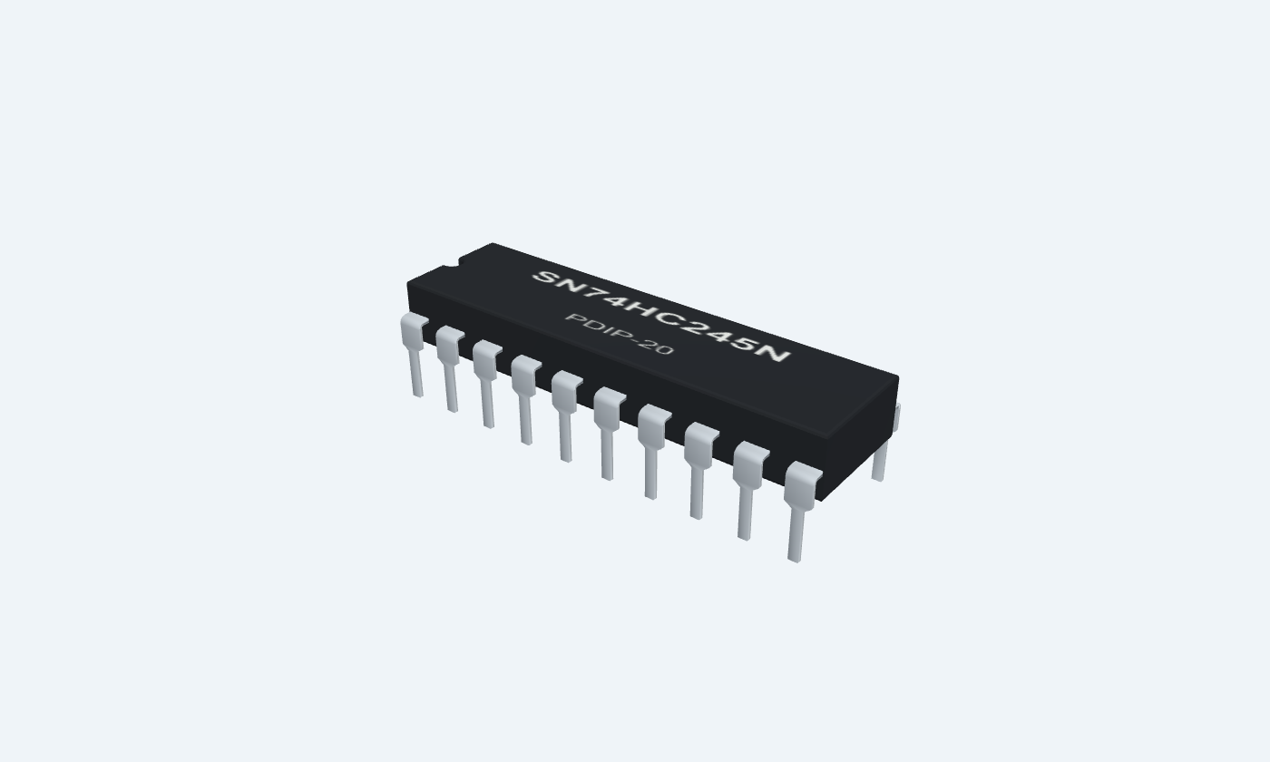
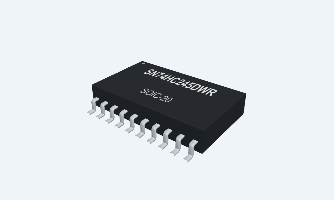

Direction and output enableEight A-side portsSupply and returnEight B-side ports
74HC245PDIP-20Top view
74HC245SOIC-20Top view
Click a lead or use the arrow keys. Top view
PIN 1 · Direction and output enable
Direction inputDIR
Function
HIGH selects A-to-B; LOW selects B-to-A while /OE is LOW.
How to connect
Tie to +5 V in this one-way demonstration.
Electrical note
Disable the bus before changing direction. Release the old source before enabling the new one.
PIN 2 · Eight A-side ports
Bidirectional logic portA1
Function
Channel 1 A-side port. Input with DIR HIGH; output with DIR LOW.
How to connect
Connect a switch to +5 V and a separate 10 kΩ pull-down to GND. A1 corresponds to B1.
Electrical note
Never drive this node externally while the transceiver is driving it.
PIN 3 · Eight A-side ports
Bidirectional logic portA2
Function
Channel 2 A-side port. Input with DIR HIGH; output with DIR LOW.
How to connect
Connect a switch to +5 V and a separate 10 kΩ pull-down to GND. A2 corresponds to B2.
Electrical note
Never drive this node externally while the transceiver is driving it.
PIN 4 · Eight A-side ports
Bidirectional logic portA3
Function
Channel 3 A-side port. Input with DIR HIGH; output with DIR LOW.
How to connect
Connect a switch to +5 V and a separate 10 kΩ pull-down to GND. A3 corresponds to B3.
Electrical note
Never drive this node externally while the transceiver is driving it.
PIN 5 · Eight A-side ports
Bidirectional logic portA4
Function
Channel 4 A-side port. Input with DIR HIGH; output with DIR LOW.
How to connect
Connect a switch to +5 V and a separate 10 kΩ pull-down to GND. A4 corresponds to B4.
Electrical note
Never drive this node externally while the transceiver is driving it.
PIN 6 · Eight A-side ports
Bidirectional logic portA5
Function
Channel 5 A-side port. Input with DIR HIGH; output with DIR LOW.
How to connect
Connect a switch to +5 V and a separate 10 kΩ pull-down to GND. A5 corresponds to B5.
Electrical note
Never drive this node externally while the transceiver is driving it.
PIN 7 · Eight A-side ports
Bidirectional logic portA6
Function
Channel 6 A-side port. Input with DIR HIGH; output with DIR LOW.
How to connect
Connect a switch to +5 V and a separate 10 kΩ pull-down to GND. A6 corresponds to B6.
Electrical note
Never drive this node externally while the transceiver is driving it.
PIN 8 · Eight A-side ports
Bidirectional logic portA7
Function
Channel 7 A-side port. Input with DIR HIGH; output with DIR LOW.
How to connect
Connect a switch to +5 V and a separate 10 kΩ pull-down to GND. A7 corresponds to B7.
Electrical note
Never drive this node externally while the transceiver is driving it.
PIN 9 · Eight A-side ports
Bidirectional logic portA8
Function
Channel 8 A-side port. Input with DIR HIGH; output with DIR LOW.
How to connect
Connect a switch to +5 V and a separate 10 kΩ pull-down to GND. A8 corresponds to B8.
Electrical note
Never drive this node externally while the transceiver is driving it.
PIN 10 · Supply and return
Ground returnGND
Function
Common return for both buses and controls.
How to connect
Connect to supply return and the bypass capacitor.
PIN 11 · Eight B-side ports
Bidirectional logic portB8
Function
Channel 8 B-side port. Output with DIR HIGH; input with DIR LOW.
How to connect
Connect through 1 kΩ to an LED anode; cathode to GND. A 100 kΩ pull-down defines the disabled node.
Electrical note
The two ports share one supply domain. This is not a dual-supply level translator.
PIN 12 · Eight B-side ports
Bidirectional logic portB7
Function
Channel 7 B-side port. Output with DIR HIGH; input with DIR LOW.
How to connect
Connect through 1 kΩ to an LED anode; cathode to GND. A 100 kΩ pull-down defines the disabled node.
Electrical note
The two ports share one supply domain. This is not a dual-supply level translator.
PIN 13 · Eight B-side ports
Bidirectional logic portB6
Function
Channel 6 B-side port. Output with DIR HIGH; input with DIR LOW.
How to connect
Connect through 1 kΩ to an LED anode; cathode to GND. A 100 kΩ pull-down defines the disabled node.
Electrical note
The two ports share one supply domain. This is not a dual-supply level translator.
PIN 14 · Eight B-side ports
Bidirectional logic portB5
Function
Channel 5 B-side port. Output with DIR HIGH; input with DIR LOW.
How to connect
Connect through 1 kΩ to an LED anode; cathode to GND. A 100 kΩ pull-down defines the disabled node.
Electrical note
The two ports share one supply domain. This is not a dual-supply level translator.
PIN 15 · Eight B-side ports
Bidirectional logic portB4
Function
Channel 4 B-side port. Output with DIR HIGH; input with DIR LOW.
How to connect
Connect through 1 kΩ to an LED anode; cathode to GND. A 100 kΩ pull-down defines the disabled node.
Electrical note
The two ports share one supply domain. This is not a dual-supply level translator.
PIN 16 · Eight B-side ports
Bidirectional logic portB3
Function
Channel 3 B-side port. Output with DIR HIGH; input with DIR LOW.
How to connect
Connect through 1 kΩ to an LED anode; cathode to GND. A 100 kΩ pull-down defines the disabled node.
Electrical note
The two ports share one supply domain. This is not a dual-supply level translator.
PIN 17 · Eight B-side ports
Bidirectional logic portB2
Function
Channel 2 B-side port. Output with DIR HIGH; input with DIR LOW.
How to connect
Connect through 1 kΩ to an LED anode; cathode to GND. A 100 kΩ pull-down defines the disabled node.
Electrical note
The two ports share one supply domain. This is not a dual-supply level translator.
PIN 18 · Eight B-side ports
Bidirectional logic portB1
Function
Channel 1 B-side port. Output with DIR HIGH; input with DIR LOW.
How to connect
Connect through 1 kΩ to an LED anode; cathode to GND. A 100 kΩ pull-down defines the disabled node.
Electrical note
The two ports share one supply domain. This is not a dual-supply level translator.
PIN 19 · Direction and output enable
Active-LOW output enable/OE
Function
LOW enables the direction-selected paths; HIGH releases both sets of drivers.
How to connect
Use 10 kΩ to +5 V and a switch to GND. Close it to enable.
Electrical note
HIGH means high impedance, not a driven LOW.
PIN 20 · Supply and return
Positive supplyVCC
Function
Powers the logic and output drivers.
How to connect
Use +5 V with 100 nF directly between pins 20 and 10.
Electrical note
Recommended operating supply: 2–6 V.
At a glance
Octal bidirectional bus transceiver
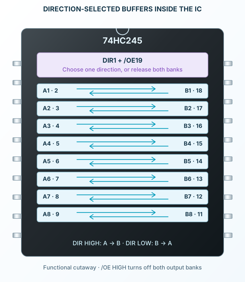
Eight noninverting paths share DIR and /OE. The selected output bank drives only while /OE is LOW; the other bank receives. /OE HIGH releases both banks.
8 Noninverting, bidirectionalParallel channels
2–6 VOperating supply
DIR + /OE Direction and active-LOW enableShared controls
−40 to +85 °CSN74 ambient
Operating profile
SN74HC245N
Direction and enable
Key parameters and their test conditions
- /OE LOW; DIR HIGH
- A inputs → B outputsConditions / notes: Noninverting, asynchronous transfer
- /OE LOW; DIR LOW
- B inputs → A outputsConditions / notes: Reverse direction
- /OE HIGH; DIR either level
- Both output banks high impedanceConditions / notes: External bias determines node voltages
- Output state
- LOW, HIGH or Z drive conditionConditions / notes: Z is not a third voltage
- Data storage
- NoneConditions / notes: Output follows after propagation delay; no clock
- Direction changes
- Disable first; release old sourceConditions / notes: Prevent bus contention during handoff
Package details
Follows the selected physical package
- Manufacturer
- Texas Instruments
- Part number
- SN74HC245N
- Package
- PDIP-20
- Connections
- 20 pins
- Mounting
- Through-hole
- Lead pitch
- 2.54 mm
- Package code
- PDIP-20
- Thermal reference
- See operating and package limits
Connections by function
Select a pin to open its function, electrical notes and wiring guidance.
Direction and output enable2 pins
Eight A-side ports8 pins
Supply and return2 pins
Eight B-side ports8 pins
Direction and output enable2 pins
Eight A-side ports8 pins
Supply and return2 pins
Eight B-side ports8 pins
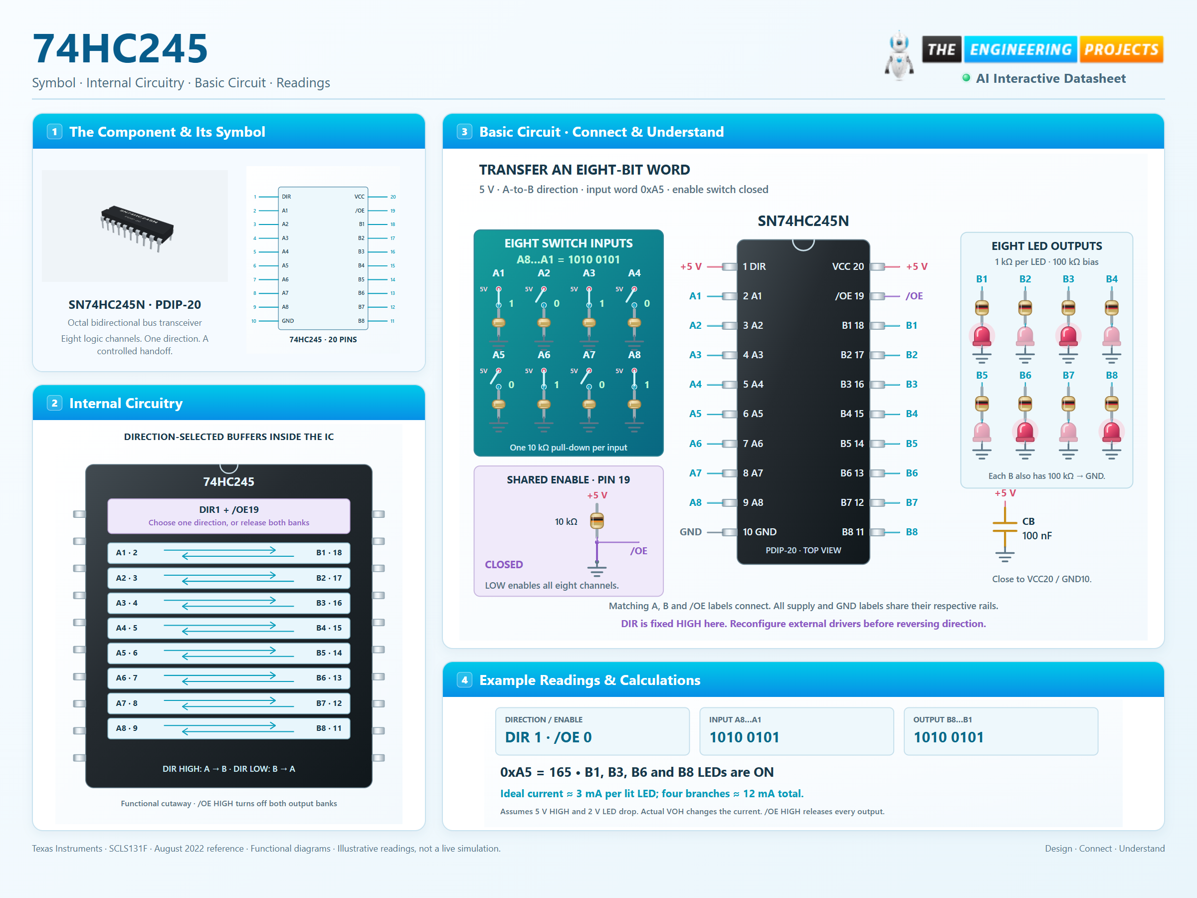
Present a byte
Eight switches establish A1 through A8. A1 is the least significant bit in this example. A8…A1 = 1010 0101 gives hexadecimal A5.
Select and enable
DIR pin 1 is held HIGH. Closing the /OE switch pulls pin 19 LOW and enables A-to-B transfer.
Observe or release
B1, B3, B6 and B8 light their LEDs. Opening /OE releases all eight drivers; external pull-downs define the disabled nodes.
Disable, release the old source, select direction and enable the new transfer. High impedance is not a logic LOW, and a shared supply does not make HC a universal voltage translator.
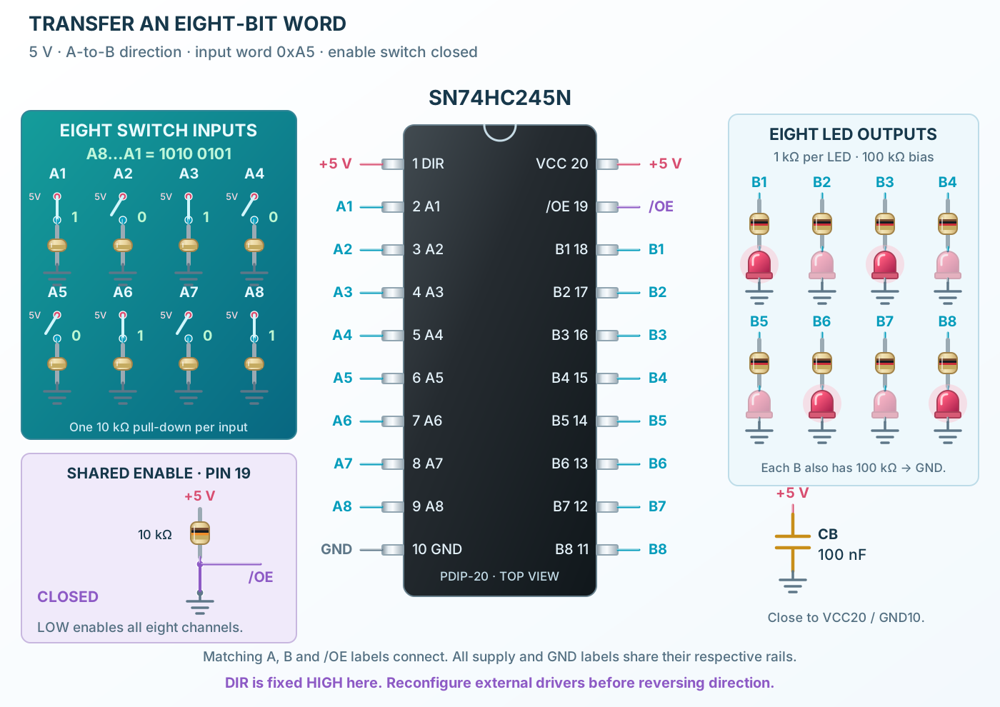
Pin reference
Select a pin to explore its function and connection.
20 pins
| Pin | Signal | Type | Function |
|---|---|---|---|
| DIR | Direction input | HIGH selects A-to-B; LOW selects B-to-A while /OE is LOW. | |
| A1 | Bidirectional logic port | Channel 1 A-side port. Input with DIR HIGH; output with DIR LOW. | |
| A2 | Bidirectional logic port | Channel 2 A-side port. Input with DIR HIGH; output with DIR LOW. | |
| A3 | Bidirectional logic port | Channel 3 A-side port. Input with DIR HIGH; output with DIR LOW. | |
| A4 | Bidirectional logic port | Channel 4 A-side port. Input with DIR HIGH; output with DIR LOW. | |
| A5 | Bidirectional logic port | Channel 5 A-side port. Input with DIR HIGH; output with DIR LOW. | |
| A6 | Bidirectional logic port | Channel 6 A-side port. Input with DIR HIGH; output with DIR LOW. | |
| A7 | Bidirectional logic port | Channel 7 A-side port. Input with DIR HIGH; output with DIR LOW. | |
| A8 | Bidirectional logic port | Channel 8 A-side port. Input with DIR HIGH; output with DIR LOW. | |
| GND | Ground return | Common return for both buses and controls. | |
| B8 | Bidirectional logic port | Channel 8 B-side port. Output with DIR HIGH; input with DIR LOW. | |
| B7 | Bidirectional logic port | Channel 7 B-side port. Output with DIR HIGH; input with DIR LOW. | |
| B6 | Bidirectional logic port | Channel 6 B-side port. Output with DIR HIGH; input with DIR LOW. | |
| B5 | Bidirectional logic port | Channel 5 B-side port. Output with DIR HIGH; input with DIR LOW. | |
| B4 | Bidirectional logic port | Channel 4 B-side port. Output with DIR HIGH; input with DIR LOW. | |
| B3 | Bidirectional logic port | Channel 3 B-side port. Output with DIR HIGH; input with DIR LOW. | |
| B2 | Bidirectional logic port | Channel 2 B-side port. Output with DIR HIGH; input with DIR LOW. | |
| B1 | Bidirectional logic port | Channel 1 B-side port. Output with DIR HIGH; input with DIR LOW. | |
| /OE | Active-LOW output enable | LOW enables the direction-selected paths; HIGH releases both sets of drivers. | |
| VCC | Positive supply | Powers the logic and output drivers. |
No pins match. Try a signal name or choose All pins.
Direction and enable
Shared by all eight channels
Manufacturer specifications 6 parameters
| Parameter | Value | Conditions / notes |
|---|---|---|
| /OE LOW; DIR HIGH | A inputs → B outputs | Noninverting, asynchronous transfer |
| /OE LOW; DIR LOW | B inputs → A outputs | Reverse direction |
| /OE HIGH; DIR either level | Both output banks high impedance | External bias determines node voltages |
| Output state | LOW, HIGH or Z drive condition | Z is not a third voltage |
| Data storage | None | Output follows after propagation delay; no clock |
| Direction changes | Disable first; release old source | Prevent bus contention during handoff |
No specifications match. Try a parameter name or a unit.
The illustrated switch/LED circuit is wired for A-to-B only. Reconfigure external sources before reversing direction.
Eight channel pairs
SN74HC245N · PDIP-20
Manufacturer specifications 10 parameters
| Parameter | Value | Conditions / notes |
|---|---|---|
| Channel 1 | A1 pin 2 ↔ B1 pin 18 | Same logic polarity in either direction |
| Channel 2 | A2 pin 3 ↔ B2 pin 17 | Same logic polarity in either direction |
| Channel 3 | A3 pin 4 ↔ B3 pin 16 | Same logic polarity in either direction |
| Channel 4 | A4 pin 5 ↔ B4 pin 15 | Same logic polarity in either direction |
| Channel 5 | A5 pin 6 ↔ B5 pin 14 | Same logic polarity in either direction |
| Channel 6 | A6 pin 7 ↔ B6 pin 13 | Same logic polarity in either direction |
| Channel 7 | A7 pin 8 ↔ B7 pin 12 | Same logic polarity in either direction |
| Channel 8 | A8 pin 9 ↔ B8 pin 11 | Same logic polarity in either direction |
| Control pins | DIR 1; /OE 19 | One direction and one enable for the entire byte |
| Power pins | VCC20; GND10 | 100 nF bypass placed close to the package |
No specifications match. Try a parameter name or a unit.
The physical arrangement differs from latch/register ICs: this device does not capture or retain data.
Supply and logic thresholds
SN74 operating conditions
Manufacturer specifications 8 parameters
| Parameter | Value | Conditions / notes |
|---|---|---|
| Recommended supply | 2–6 V | 5 V demonstration |
| Operating temperature | −40 to +85°C | SN74 grade; do not substitute SN54 limits |
| HIGH input at 4.5 V | At least 3.15 V | HC CMOS threshold |
| LOW input at 4.5 V | At most 1.35 V | Intermediate region is unspecified |
| Thresholds at 2 V | HIGH ≥1.5 V; LOW ≤0.5 V | Manufacturer test point |
| Thresholds at 6 V | HIGH ≥4.2 V; LOW ≤1.8 V | A 3.3 V source does not guarantee HIGH here |
| Input rise/fall time maximum | 1000 / 500 / 400 ns | At 2 / 4.5 / 6 V |
| Normal port voltage | Between GND and VCC | Respect power sequencing and clamp-current limits |
No specifications match. Try a parameter name or a unit.
A single VCC powers both buses. Use a suitable level translator where independent voltage domains are required.
Drive, leakage and current
Defined test conditions
Manufacturer specifications 7 parameters
| Parameter | Value | Conditions / notes |
|---|---|---|
| HIGH output at 4.5 V, −6 mA | 4.3 V typical; 3.98 V minimum at 25°C | 3.84 V minimum across SN74 temperature range |
| LOW output at 4.5 V, 6 mA | 0.17 V typical; 0.26 V maximum at 25°C | 0.33 V maximum across SN74 temperature range |
| Light-load output at 4.5 V | HIGH ≥4.4 V; LOW ≤0.1 V | 20 µA load |
| Disabled-port leakage at 6 V | ±0.01 µA typical; ±0.5 µA maximum at 25°C | ±5 µA maximum across SN74 range |
| DIR / OE input leakage at 6 V | ±0.1 µA maximum at 25°C | ±1 µA maximum across temperature |
| Static supply current at 6 V | 8 µA max at 25°C; 80 µA max over range | Inputs at supply rails, no output load |
| Control input capacitance | 3 pF typical; 10 pF maximum | DIR / OE, 2–6 V |
No specifications match. Try a parameter name or a unit.
Output drive and supply current are separate quantities. Add the loads of all active channels when checking package current.
Transfer and bus-handoff timing
4.5 V · CL = 50 pF
Manufacturer specifications 6 parameters
| Parameter | Value | Conditions / notes |
|---|---|---|
| Data propagation A↔B | 15 ns typical; 21 ns maximum at 25°C | 26 ns maximum across −40…85°C |
| Enable /OE to output | 23 ns typical; 46 ns maximum at 25°C | 58 ns maximum across temperature |
| Disable /OE to Z | 25 ns typical; 40 ns maximum at 25°C | 50 ns maximum across temperature |
| Output transition | 8 ns typical; 12 ns maximum at 25°C | 15 ns maximum across temperature |
| Data delay with 150 pF load | 18 ns typical; 27 ns max at 25°C | 34 ns maximum across SN74 temperature range |
| Break-before-make timing | Account for worst-case delay and control skew | A released node may settle slowly through external bias |
No specifications match. Try a parameter name or a unit.
Typical values are descriptive, not guaranteed design limits. The headline 12 ns value is the 6 V, 50 pF typical data delay.
Eight-bit LED transfer
5 V · DIR HIGH · /OE LOW
Manufacturer specifications 8 parameters
| Parameter | Value | Conditions / notes |
|---|---|---|
| Input word | A8…A1 = 1010 0101 | 0xA5 = decimal 165 |
| Input switches | Each A pin → switch → +5 V | Separate 10 kΩ from each A pin to GND |
| Output LEDs | Each B pin → 1 kΩ → LED anode → cathode to GND | One resistor per LED |
| Disabled-output bias | 100 kΩ from every B pin to GND | Defines nodes when the IC releases its drivers |
| Enable control | 10 kΩ pull-up on pin 19; switch to GND | Open = disabled, closed = enabled |
| Illustrated LEDs on | B1, B3, B6 and B8 | Four HIGH outputs |
| Ideal current | About 3 mA per lit red LED, about 12 mA total | Assumes 5 V output and 2 V LED drop; actual VOH changes it |
| Local bypass | 100 nF from VCC20 to GND10 | Short connection loop |
No specifications match. Try a parameter name or a unit.
The drawn switch positions are illustrative steady states. No clock is driven by the switches.
Current and layout boundaries
Stress ratings are not operating targets
Manufacturer specifications 7 parameters
| Parameter | Value | Conditions / notes |
|---|---|---|
| Absolute VCC maximum | 7 V | Normal operating maximum is 6 V |
| Absolute per-output current | ±35 mA | Use the specified loaded output levels for real designs |
| Absolute VCC / GND current | ±70 mA | Total package current, not per channel |
| Absolute clamp current | ±20 mA | Avoid normal use of protection diodes as voltage conversion |
| Bus contention | Never enable opposing driven levels | Disable before changing source ownership |
| Unused channel bias | Hold inputs at a valid rail | Use resistive bias if a port may become an output |
| Routing | Short returns and close bypass | Reduce capacitive load and ringing |
No specifications match. Try a parameter name or a unit.
Do not power LEDs, relays or other loads without checking their load currents and required external drivers.
Parallel bus buffering
Transfer a byte between compatible same-supply logic domains with controlled ownership.
Manufacturer application guideBidirectional interfaces
Select which side supplies data and release both banks when idle.
Manufacturer application guideLED logic demonstrations
Observe an eight-bit pattern with separate current-limiting resistors and modest loads.
Manufacturer application guideTake it into ProTech
Find 74HC245 in the Components Library to place its schematic symbol and connect its pins.
Reference page · circuit simulation model not yet availableOpen ProTech