Real View
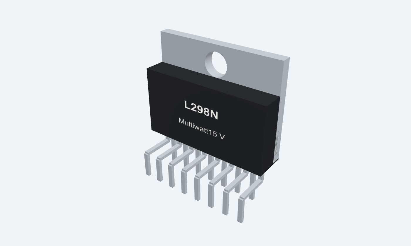
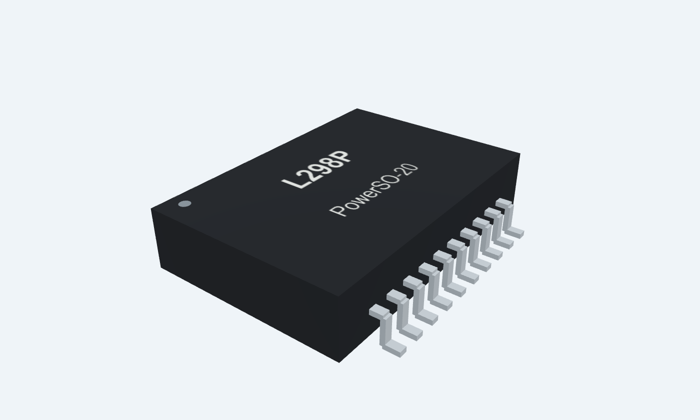
Control direction, braking and current return—with two complete bridges.
L298 is a bipolar dual full-bridge driver for DC motors, stepper windings and other inductive loads. Its two enable inputs independently control the two bridges, while separate logic and motor rails keep their supply functions distinct. This reference covers L298N in the 15-lead vertical Multiwatt package and L298P in PowerSO-20. The SMD version has different physical pin numbers, extra ground contacts and two NC pins; all four visual views follow the selected package. Use external fast flyback diodes, local bypass capacitors and a suitable thermal path. The two sense returns can feed external current-control circuits; the IC does not provide a complete automatic current regulator by itself.
Select a pin to explore its connection
Click a lead or use the arrow keys. Front view · leads down · tab is GND
Common emitter return of the two lower transistors in bridge A.
Connect a low-inductance current-sense resistor to power ground, or ground directly when sensing is not used.
Do not leave open. Sensing requires an external controller; this pin alone does not regulate current.
First power output of bridge A.
Connect to one motor lead; the other lead goes to OUT2.
Add external fast flyback diodes to the supply and ground rails.
Second power output of bridge A.
Connect to the other motor lead.
The motor is between OUT1 and OUT2, not between one output and ground.
Feeds the bridge output transistors.
Use a local 100 nF capacitor to GND and suitable bulk capacitance.
The example uses 12 V. Operating maximum is 46 V; allow room for inductive transients.
Controls OUT1 while ENA is HIGH.
Connect to a defined controller logic output.
HIGH enables bridge A; LOW disables both outputs.
Use a control output with a pull-down so the motor is disabled during reset.
Controls OUT2 while ENA is HIGH.
Connect to the second direction-control output.
Reference ground; the Multiwatt metal tab is connected to this node.
Join controller, supply and sense-resistor returns. Connect every PowerSO ground contact.
Supplies the internal control logic independently of VS.
Use 5 V with a local 100 nF bypass to GND.
Specified operating range is 4.5–7 V.
Controls OUT3 while ENB is HIGH.
Hold LOW in this one-motor example.
HIGH enables bridge B.
Hold LOW when bridge B is unused.
Controls OUT4 while ENB is HIGH.
Hold LOW in this example.
First output of bridge B.
Leave open when bridge B is unused; otherwise connect the second motor or winding.
Second output of bridge B.
Leave open when bridge B is unused.
Emitter return for bridge B.
Connect to GND in this example. Use a separate low-inductance shunt when sensing bridge B.
Unconnected contact present only on PowerSO-20.
Leave open.
Unconnected contact present only on PowerSO-20.
Leave open.
Additional ground contact on PowerSO-20; not an extra control signal.
Connect to the same ground plane as the other GND contacts.
Additional ground contact on PowerSO-20; not an extra control signal.
Connect to the same ground plane as the other GND contacts.
Additional ground contact on PowerSO-20; not an extra control signal.
Connect to the same ground plane as the other GND contacts.
Each enabled output pair can reverse a motor or command braking. VS provides motor energy; VSS supplies the control logic.
L298N · Multiwatt15 V
| Property | Details |
|---|---|
| Manufacturer | STMicroelectronics |
| Part number | L298N |
| Package | Multiwatt15 V |
| Connections | 15 pins |
| Mounting | Through-hole |
| Lead pitch | 1.27 mm · staggered rows |
| Package code | MW15V |
| Thermal reference | Grounded metal tab; heatsinking required according to dissipation |
ST DS0218 · keep conditions attached
Scroll sideways to see all columns.
| Parameter | Value | Conditions / notes |
|---|---|---|
| Logic supply VSS | 4.5–7 V | 5 V nominal |
| Motor supply VS | VIH + 2.5 V to 46 V | Specified operative condition; example uses 12 V |
| Input / enable HIGH | 2.3 V to VSS | TTL-compatible thresholds |
| Input / enable LOW | −0.3 to 1.5 V | Normal LOW is 0 V |
| Operating junction | −25 to 130°C | Do not treat as an ambient specification |
| Local bypass capacitors | 100 nF on each supply | VS to GND and VSS to GND, near the IC |
No specifications match. Try a parameter name or a unit.
Keep enable inputs LOW before switching supplies on or off.
One motor between OUT1 and OUT2
Scroll sideways to see all columns.
| Parameter | Value | Conditions / notes |
|---|---|---|
| EN LOW; inputs any | Coast · Z / Z | No commanded drive; external diode paths still operate |
| EN HIGH; IN1 HIGH, IN2 LOW | Direction A | OUT1 HIGH, OUT2 LOW |
| EN HIGH; IN1 LOW, IN2 HIGH | Direction B | OUT1 LOW, OUT2 HIGH |
| EN HIGH; both inputs LOW | Brake to GND | Both outputs LOW |
| EN HIGH; both inputs HIGH | Brake to VS | Both outputs HIGH |
No specifications match. Try a parameter name or a unit.
Direction labels are commands. Mechanical direction depends on wiring; stop/reversal current must stay within limits.
VS = 42 V; VSS = 5 V; TJ = 25°C
Scroll sideways to see all columns.
| Parameter | Value | Conditions / notes |
|---|---|---|
| High-side drop at 1 A | 1.35 V typical; 1.7 V maximum | Source transistor |
| Low-side drop at 1 A | 1.2 V typical; 1.6 V maximum | Sense return grounded |
| Total drop at 1 A | 3.2 V maximum | Combined bridge specification |
| High-side / low-side at 2 A | 2.0 V / 1.7 V typical | 2.7 V / 2.3 V maximum individually |
| Total drop at 2 A | 4.9 V maximum | Combined bridge specification |
| 12 V, 1 A example | 9.45 V across motor; 2.55 W bridge loss | Uses summed typical drops, excludes other losses |
No specifications match. Try a parameter name or a unit.
The example is an estimate, not a regulated motor voltage or a safe continuous thermal allowance.
Multiwatt15 → PowerSO-20
Scroll sideways to see all columns.
| Parameter | Value | Conditions / notes |
|---|---|---|
| SENSE A / SENSE B | 1 / 15 → 2 / 19 | Separate bridge returns |
| OUT1 / OUT2 | 2 / 3 → 4 / 5 | Motor A |
| VS / VSS | 4 / 9 → 6 / 12 | Power stage / logic |
| IN1 / IN2 | 5 / 7 → 7 / 9 | Bridge A inputs |
| ENA / ENB | 6 / 11 → 8 / 14 | Bridge enables |
| IN3 / IN4 | 10 / 12 → 13 / 15 | Bridge B inputs |
| OUT3 / OUT4 | 13 / 14 → 16 / 17 | Motor B |
| Ground | 8 → 1, 10, 11, 20 | All ground contacts required |
| NC | None → 3, 18 | Leave open |
No specifications match. Try a parameter name or a unit.
The interactive pinout changes physical numbering with the selected package. Extra SMD grounds retain their ground function.
L298N front view · 5 V logic / 12 V motor
Scroll sideways to see all columns.
| Parameter | Value | Conditions / notes |
|---|---|---|
| Motor leads | OUT1 pin 2 and OUT2 pin 3 | Use a motor whose stall and braking currents suit the driver |
| Direction / enable | IN1 pin 5, IN2 pin 7, ENA pin 6 | Controller nets IN1, IN2, ENA; 10 kΩ enable pull-down |
| Power / logic | VS pin 4 = 12 V; VSS pin 9 = 5 V | 100 nF local bypass on both rails; bulk motor capacitance |
| Ground and returns | Pins 1, 8 and 15 to GND | Direct sense returns for this nonsensing example |
| Unused bridge B | 10, 11, 12 LOW; 13, 14 open | Keep outputs disabled |
| External diodes | Four fast diodes per active bridge | Output to VS and GND to output; low VF; trr ≤200 ns |
| Thermal design | Heatsink and short power paths | Check stall current, winding energy and supply absorption |
No specifications match. Try a parameter name or a unit.
Matched net labels are electrical connections. The illustration shows a bare IC; a breakout board may contain different supporting components.
Operating limits are not interchangeable with absolute maxima
Scroll sideways to see all columns.
| Parameter | Value | Conditions / notes |
|---|---|---|
| VS / VSS absolute maximum | 50 V / 7 V | Do not design to the transient stress ceiling |
| DC output current | 2 A per channel | Absolute maximum; thermal and braking constraints apply |
| Peak current | 2.5 A repetitive; 3 A nonrepetitive | 80% ON, 10 ms ON / 100 ms single pulse respectively |
| Multiwatt RθJC / RθJA | 3°C/W / 35°C/W maximum | Manufacturer thermal conditions |
| PowerSO RθJA | 13°C/W maximum | Mounted on aluminum substrate; not ordinary FR4 |
| Multiwatt geometry | 20.2 mm body width; 1.27 mm lead pitch | 15 leads in staggered rows; vertical L298N |
| PowerSO geometry | 11.0 × 15.9 mm nominal body; 1.27 mm pitch | L298P, slug down; 20 numbered leads |
| Generic footprint downloads | TEP suggested land patterns | Check purchased outline, stencil, vias and assembly process |
No specifications match. Try a parameter name or a unit.
Thermal shutdown is included; automatic load-current regulation needs external circuitry.
Select a pin for its function, connection guidance and electrical notes.
Follow the labeled connections and functional stages
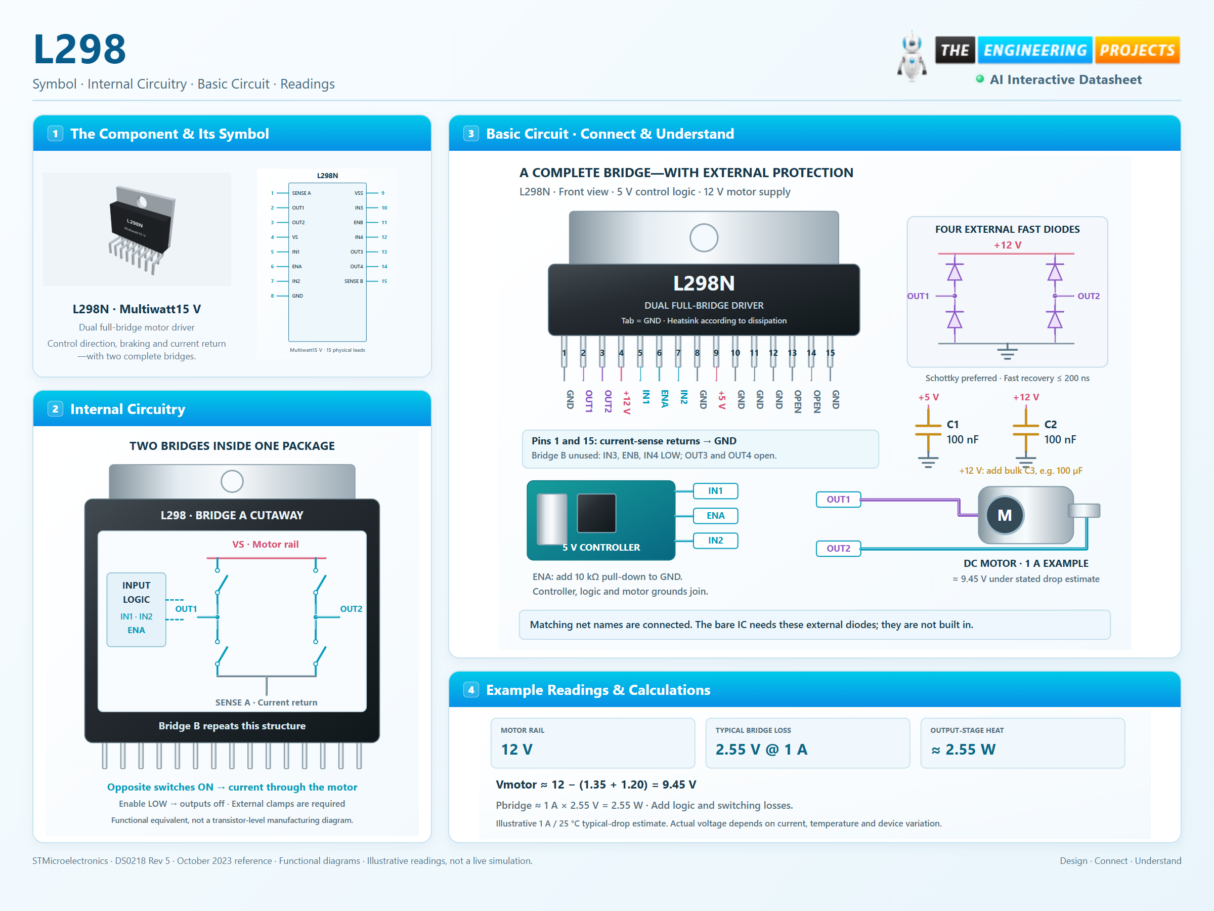
3 stages · Explore one step at a time
ENA and ENB independently control the bridges. Keep enables LOW during power transitions and controller reset.
Opposite direction inputs apply opposite output polarities. Equal inputs with enable HIGH bring the motor terminals to the same rail for braking.
Current returns through SENSE A or SENSE B. External fast diodes carry inductive current during transitions, while copper and heatsinking remove heat.
Switch the inputs to explore one complete motor bridge.
Enable JavaScript to explore bridge control.
Logic-state explorer only. Commanded direction is shown, not simulated speed. Current, inertia, voltage drop, diode transients and heating are not calculated. External flyback diodes and a common ground are required for a real inductive load.
A physical IC, named control nets and four external flyback diodes.
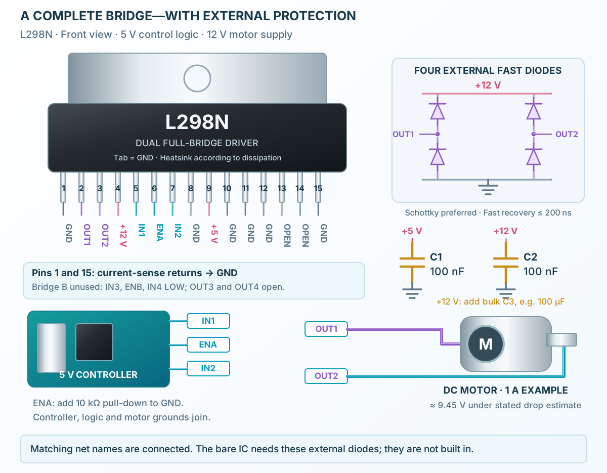
Follow the component values and pin connections
Add a 100 nF bypass on each rail and motor bulk capacitance. All GND symbols share one return.
Use OUT1 and OUT2. Upper diodes point from output to VS; lower diodes point from GND to output.
Use IN1 and IN2 for direction and ENA for enable. Hold unused inputs LOW and unused outputs open.
Two bipolar full bridges inside the package; one shown in detail.
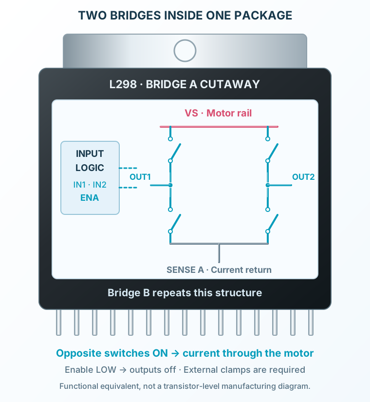
Select a stage to see its role and connections
Direction inputs choose output states only while the corresponding enable is HIGH.
Diagonal devices reverse the motor voltage; equal outputs command braking.
The two low-side emitters share SENSE A; the other bridge uses SENSE B. External circuitry can measure these currents.
Signal names, electrical functions and connection guidance
Scroll within the table to see all columns and rows.
| Pin | Signal | Type | Function & connection |
|---|---|---|---|
| SENSE A | Bridge A current return | Common emitter return of the two lower transistors in bridge A.Connection guidanceConnect a low-inductance current-sense resistor to power ground, or ground directly when sensing is not used. Do not leave open. Sensing requires an external controller; this pin alone does not regulate current. | |
| OUT1 | Motor A terminal | First power output of bridge A.Connection guidanceConnect to one motor lead; the other lead goes to OUT2. Add external fast flyback diodes to the supply and ground rails. | |
| OUT2 | Motor A terminal | Second power output of bridge A.Connection guidanceConnect to the other motor lead. The motor is between OUT1 and OUT2, not between one output and ground. | |
| VS | Power-stage supply | Feeds the bridge output transistors.Connection guidanceUse a local 100 nF capacitor to GND and suitable bulk capacitance. The example uses 12 V. Operating maximum is 46 V; allow room for inductive transients. | |
| IN1 | Bridge A direction input | Controls OUT1 while ENA is HIGH.Connection guidanceConnect to a defined controller logic output. | |
| ENA | Bridge A enable | HIGH enables bridge A; LOW disables both outputs.Connection guidanceUse a control output with a pull-down so the motor is disabled during reset. | |
| IN2 | Bridge A direction input | Controls OUT2 while ENA is HIGH.Connection guidanceConnect to the second direction-control output. | |
| GND | Logic and power reference | Reference ground; the Multiwatt metal tab is connected to this node.Connection guidanceJoin controller, supply and sense-resistor returns. Connect every PowerSO ground contact. | |
| VSS | Logic supply | Supplies the internal control logic independently of VS.Connection guidanceUse 5 V with a local 100 nF bypass to GND. Specified operating range is 4.5–7 V. | |
| IN3 | Bridge B direction input | Controls OUT3 while ENB is HIGH.Connection guidanceHold LOW in this one-motor example. | |
| ENB | Bridge B enable | HIGH enables bridge B.Connection guidanceHold LOW when bridge B is unused. | |
| IN4 | Bridge B direction input | Controls OUT4 while ENB is HIGH.Connection guidanceHold LOW in this example. | |
| OUT3 | Motor B terminal | First output of bridge B.Connection guidanceLeave open when bridge B is unused; otherwise connect the second motor or winding. | |
| OUT4 | Motor B terminal | Second output of bridge B.Connection guidanceLeave open when bridge B is unused. | |
| SENSE B | Bridge B current return | Emitter return for bridge B.Connection guidanceConnect to GND in this example. Use a separate low-inductance shunt when sensing bridge B. | |
| NC | No internal connection | Unconnected contact present only on PowerSO-20.Connection guidanceLeave open. | |
| NC | No internal connection | Unconnected contact present only on PowerSO-20.Connection guidanceLeave open. | |
| GND | Additional SMD ground | Additional ground contact on PowerSO-20; not an extra control signal.Connection guidanceConnect to the same ground plane as the other GND contacts. | |
| GND | Additional SMD ground | Additional ground contact on PowerSO-20; not an extra control signal.Connection guidanceConnect to the same ground plane as the other GND contacts. | |
| GND | Additional SMD ground | Additional ground contact on PowerSO-20; not an extra control signal.Connection guidanceConnect to the same ground plane as the other GND contacts. |
No pins match these filters. Try another signal name or reset the filters.
ST DS0218 · keep conditions attached
Scroll within the table to see all columns and rows.
| Parameter | Value | Conditions / notes |
|---|---|---|
| Logic supply VSS | 4.5–7 V | 5 V nominal |
| Motor supply VS | VIH + 2.5 V to 46 V | Specified operative condition; example uses 12 V |
| Input / enable HIGH | 2.3 V to VSS | TTL-compatible thresholds |
| Input / enable LOW | −0.3 to 1.5 V | Normal LOW is 0 V |
| Operating junction | −25 to 130°C | Do not treat as an ambient specification |
| Local bypass capacitors | 100 nF on each supply | VS to GND and VSS to GND, near the IC |
No specifications match. Try a parameter name or a unit.
Keep enable inputs LOW before switching supplies on or off.
One motor between OUT1 and OUT2
Scroll within the table to see all columns and rows.
| Parameter | Value | Conditions / notes |
|---|---|---|
| EN LOW; inputs any | Coast · Z / Z | No commanded drive; external diode paths still operate |
| EN HIGH; IN1 HIGH, IN2 LOW | Direction A | OUT1 HIGH, OUT2 LOW |
| EN HIGH; IN1 LOW, IN2 HIGH | Direction B | OUT1 LOW, OUT2 HIGH |
| EN HIGH; both inputs LOW | Brake to GND | Both outputs LOW |
| EN HIGH; both inputs HIGH | Brake to VS | Both outputs HIGH |
No specifications match. Try a parameter name or a unit.
Direction labels are commands. Mechanical direction depends on wiring; stop/reversal current must stay within limits.
VS = 42 V; VSS = 5 V; TJ = 25°C
Scroll within the table to see all columns and rows.
| Parameter | Value | Conditions / notes |
|---|---|---|
| High-side drop at 1 A | 1.35 V typical; 1.7 V maximum | Source transistor |
| Low-side drop at 1 A | 1.2 V typical; 1.6 V maximum | Sense return grounded |
| Total drop at 1 A | 3.2 V maximum | Combined bridge specification |
| High-side / low-side at 2 A | 2.0 V / 1.7 V typical | 2.7 V / 2.3 V maximum individually |
| Total drop at 2 A | 4.9 V maximum | Combined bridge specification |
| 12 V, 1 A example | 9.45 V across motor; 2.55 W bridge loss | Uses summed typical drops, excludes other losses |
No specifications match. Try a parameter name or a unit.
The example is an estimate, not a regulated motor voltage or a safe continuous thermal allowance.
Multiwatt15 → PowerSO-20
Scroll within the table to see all columns and rows.
| Parameter | Value | Conditions / notes |
|---|---|---|
| SENSE A / SENSE B | 1 / 15 → 2 / 19 | Separate bridge returns |
| OUT1 / OUT2 | 2 / 3 → 4 / 5 | Motor A |
| VS / VSS | 4 / 9 → 6 / 12 | Power stage / logic |
| IN1 / IN2 | 5 / 7 → 7 / 9 | Bridge A inputs |
| ENA / ENB | 6 / 11 → 8 / 14 | Bridge enables |
| IN3 / IN4 | 10 / 12 → 13 / 15 | Bridge B inputs |
| OUT3 / OUT4 | 13 / 14 → 16 / 17 | Motor B |
| Ground | 8 → 1, 10, 11, 20 | All ground contacts required |
| NC | None → 3, 18 | Leave open |
No specifications match. Try a parameter name or a unit.
The interactive pinout changes physical numbering with the selected package. Extra SMD grounds retain their ground function.
L298N front view · 5 V logic / 12 V motor
Scroll within the table to see all columns and rows.
| Parameter | Value | Conditions / notes |
|---|---|---|
| Motor leads | OUT1 pin 2 and OUT2 pin 3 | Use a motor whose stall and braking currents suit the driver |
| Direction / enable | IN1 pin 5, IN2 pin 7, ENA pin 6 | Controller nets IN1, IN2, ENA; 10 kΩ enable pull-down |
| Power / logic | VS pin 4 = 12 V; VSS pin 9 = 5 V | 100 nF local bypass on both rails; bulk motor capacitance |
| Ground and returns | Pins 1, 8 and 15 to GND | Direct sense returns for this nonsensing example |
| Unused bridge B | 10, 11, 12 LOW; 13, 14 open | Keep outputs disabled |
| External diodes | Four fast diodes per active bridge | Output to VS and GND to output; low VF; trr ≤200 ns |
| Thermal design | Heatsink and short power paths | Check stall current, winding energy and supply absorption |
No specifications match. Try a parameter name or a unit.
Matched net labels are electrical connections. The illustration shows a bare IC; a breakout board may contain different supporting components.
Operating limits are not interchangeable with absolute maxima
Scroll within the table to see all columns and rows.
| Parameter | Value | Conditions / notes |
|---|---|---|
| VS / VSS absolute maximum | 50 V / 7 V | Do not design to the transient stress ceiling |
| DC output current | 2 A per channel | Absolute maximum; thermal and braking constraints apply |
| Peak current | 2.5 A repetitive; 3 A nonrepetitive | 80% ON, 10 ms ON / 100 ms single pulse respectively |
| Multiwatt RθJC / RθJA | 3°C/W / 35°C/W maximum | Manufacturer thermal conditions |
| PowerSO RθJA | 13°C/W maximum | Mounted on aluminum substrate; not ordinary FR4 |
| Multiwatt geometry | 20.2 mm body width; 1.27 mm lead pitch | 15 leads in staggered rows; vertical L298N |
| PowerSO geometry | 11.0 × 15.9 mm nominal body; 1.27 mm pitch | L298P, slug down; 20 numbered leads |
| Generic footprint downloads | TEP suggested land patterns | Check purchased outline, stencil, vias and assembly process |
No specifications match. Try a parameter name or a unit.
Thermal shutdown is included; automatic load-current regulation needs external circuitry.
No matching rowsTry a pin name, parameter, unit or test condition, or reset the filters.
Independently command direction, braking and coasting for two suitable brushed motors.
Manufacturer application guideUse the two bridges for two windings with an appropriate external current and step controller.
Manufacturer application guideCompare logic truth tables, real voltage loss, sense returns and external inductive current paths.
Manufacturer application guideFind L298 in the Components Library to place its schematic symbol and connect its pins.
Reference page · circuit simulation model not yet availableOpen ProTech