 BETA
Wire both rails and ground
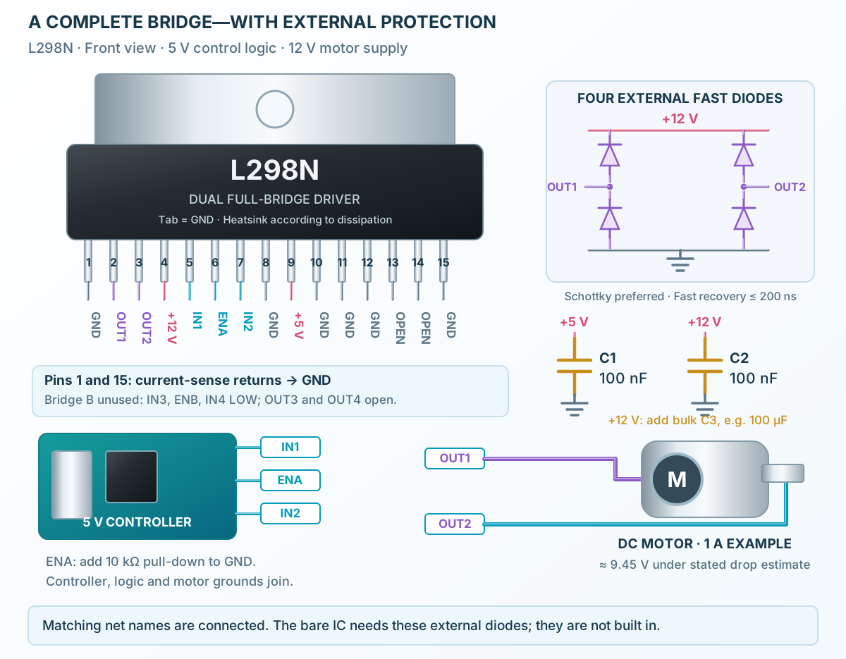
Add a 100 nF bypass on each rail and motor bulk capacitance. All GND symbols share one return.
Build a basic L298 circuit with labeled pins, component values and connection guidance.
A physical IC, named control nets and four external flyback diodes.
Follow the component values and pin connections
Add a 100 nF bypass on each rail and motor bulk capacitance. All GND symbols share one return.
Use OUT1 and OUT2. Upper diodes point from output to VS; lower diodes point from GND to output.
Use IN1 and IN2 for direction and ENA for enable. Hold unused inputs LOW and unused outputs open.