 BETA
L298 Working Principle
Learn how L298 works with an illustrated explanation and practical readings.
L298 at a glance
Follow the labeled connections and functional stages
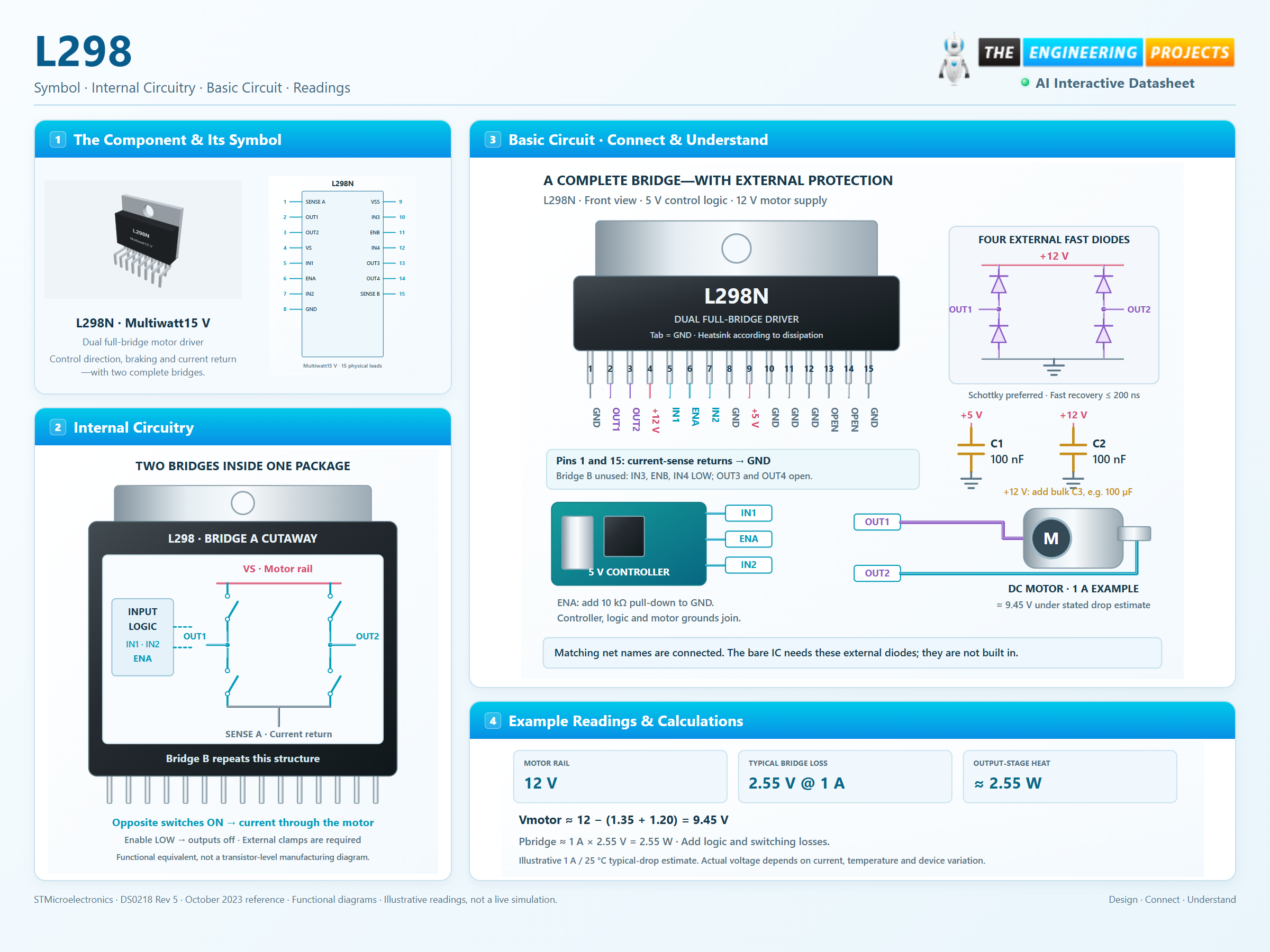
How it works
3 stages · Explore one step at a time
Enable the output pair
ENA and ENB independently control the bridges. Keep enables LOW during power transitions and controller reset.
Select a diagonal or a brake state
Opposite direction inputs apply opposite output polarities. Equal inputs with enable HIGH bring the motor terminals to the same rail for braking.
Manage the current path
Current returns through SENSE A or SENSE B. External fast diodes carry inductive current during transitions, while copper and heatsinking remove heat.
Direction, brake or coast?
Switch the inputs to explore one complete motor bridge.
Enable JavaScript to explore bridge control.
Logic-state explorer only. Commanded direction is shown, not simulated speed. Current, inertia, voltage drop, diode transients and heating are not calculated. External flyback diodes and a common ground are required for a real inductive load.