 BETA
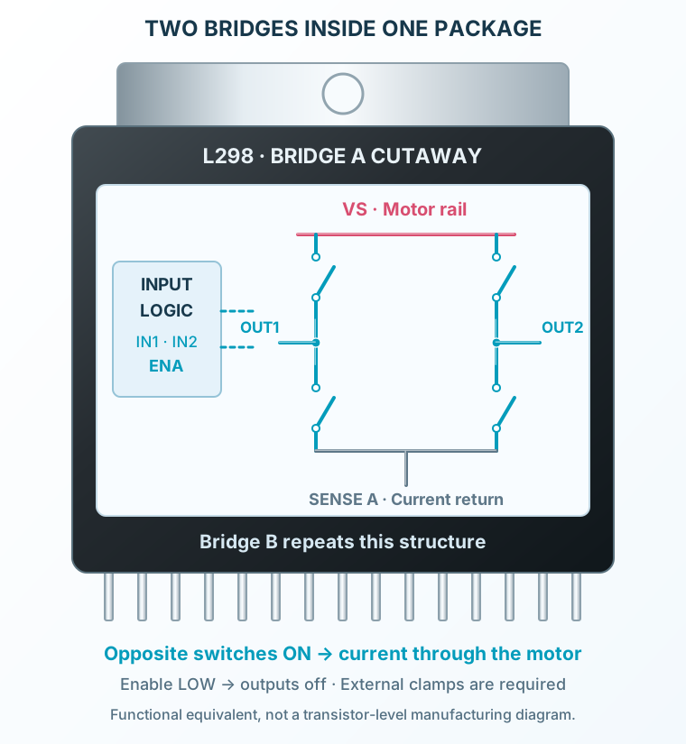
Logic controls the switches
Direction inputs choose output states only while the corresponding enable is HIGH.
Explore the internal circuitry and functional stages of L298.
Two bipolar full bridges inside the package; one shown in detail.
Select a stage to see its role and connections
Direction inputs choose output states only while the corresponding enable is HIGH.
Diagonal devices reverse the motor voltage; equal outputs command braking.
The two low-side emitters share SENSE A; the other bridge uses SENSE B. External circuitry can measure these currents.