LED (5 mm)Through-hole indicator LED · Kingbright WP7113 family
Light from current: the resistor decides, the colour sets the voltage.
Manufacturer-referenced
Kingbright · WP7113QBC/D
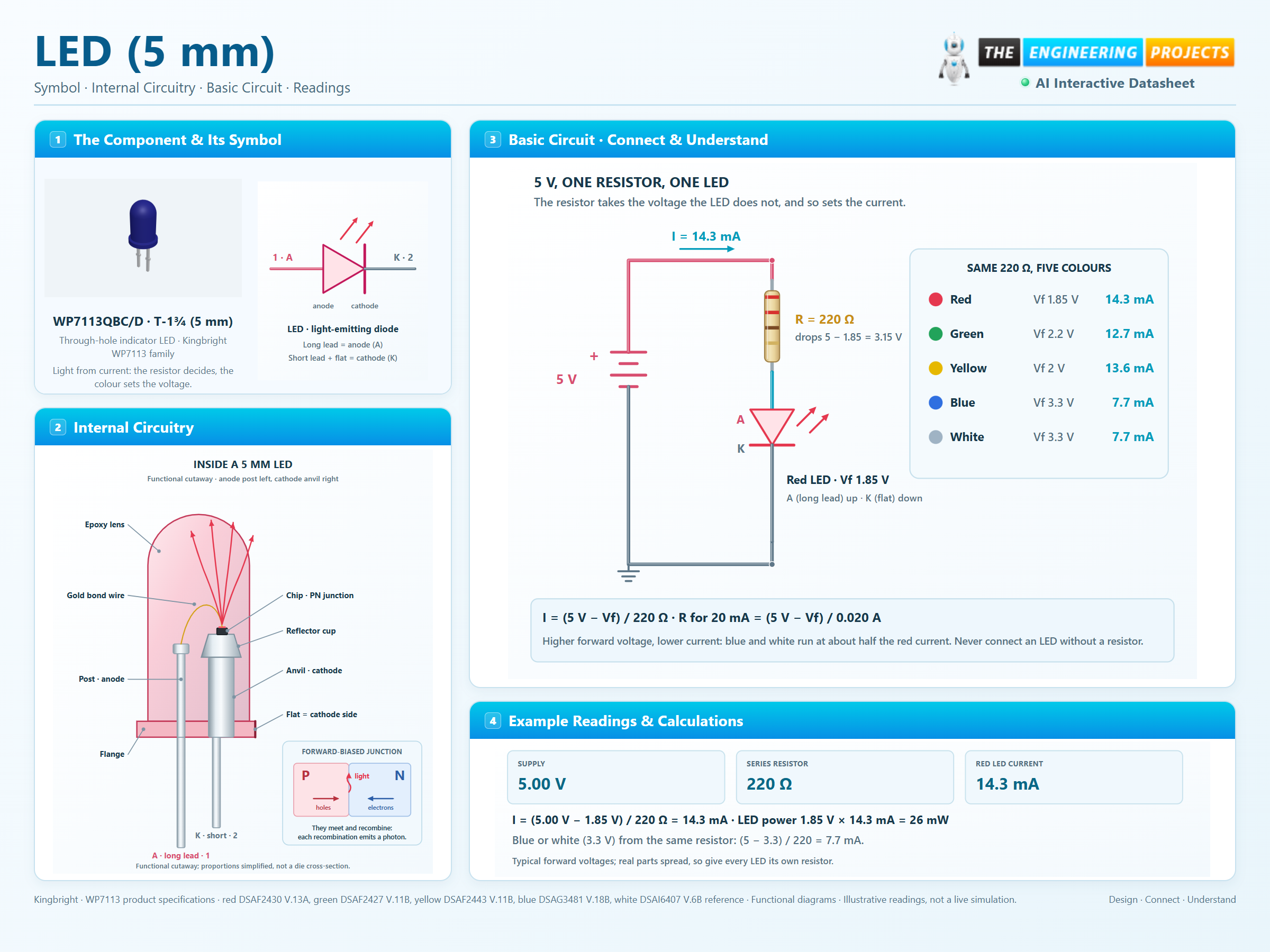
T-1¾ (5 mm)WP7113 product specifications · red DSAF2430 V.13A, green DSAF2427 V.11B, yellow DSAF2443 V.11B, blue DSAG3481 V.18B, white DSAI6407 V.6BAn LED (light-emitting diode) is a diode that gives off light when current flows from its anode to its cathode. Electrons and holes recombine in the junction and release their energy as photons; the semiconductor material sets the colour and, with it, the forward voltage. An LED is driven by current, not by voltage. Above its forward voltage the current rises very steeply, so every LED needs something that limits it, normally a series resistor: R = (supply − Vf) / I. The same resistor gives a red LED about twice the current of a blue one, because blue needs 3.3 V and red only 1.85 V. This page uses the Kingbright WP7113 family of 5 mm (T-1¾) LEDs, one product specification per colour. The longer lead is the anode; the cathode is the shorter lead beside the flat on the flange. The page numbers them 1 = A and 2 = K, as ProTech and the KiCad footprint do.
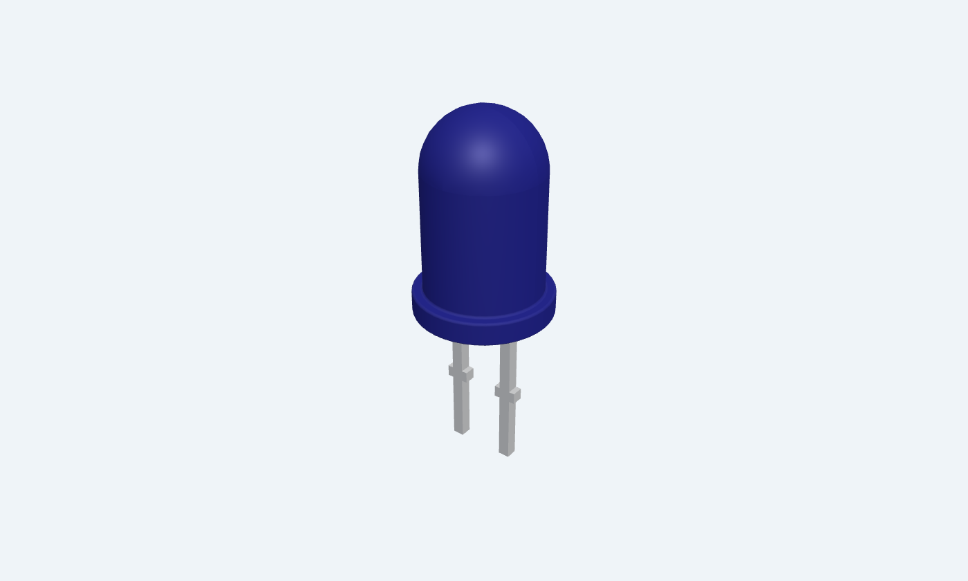

2Physical pins
WP7113QBC/DT-1¾ (5 mm)
Manufacturer-referencedKingbright
Pin diagram
Select a pin to explore its connection
Highlight
LED (5 mm)T-1¾ (5 mm)Top view · flat and short lead = cathode
Click a lead or use the arrow keys. Top view · flat and short lead = cathode
PIN A · Anode · long lead
Anode (+)A
Function
The longer lead. Conventional current enters here when the LED is forward biased.
How to connect
Connect to the supply or a microcontroller pin through the series resistor.
Electrical note
Forward voltage at 20 mA: 1.85 V red, 2.2 V green, 2.0 V yellow, 3.3 V blue and white (typical).
PIN K · Cathode · flat side
Cathode (−)K
Function
The shorter lead, next to the flat on the flange. Current leaves the LED here.
How to connect
Connect to ground (or to a pin that sinks current).
Electrical note
Never more than 5 V reverse: the LED is not a rectifier.
Key specifications
Choose the current first (5–20 mA for an indicator), then the resistor from the supply and the colour’s forward voltage. Without a resistor the current is limited only by the supply and the LED burns out.
Forward voltage1.85–3.3 V typical at 20 mA · red to white
Continuous forward current30 mA maximum · green 25 mA
Reverse voltage5 V maximum · never use it as a rectifier
Junction limit115 °C · green 110 °C
Package details
WP7113QBC/D · T-1¾ (5 mm)
| Property | Details |
|---|---|
| Manufacturer | Kingbright |
| Part number | WP7113QBC/D |
| Package | T-1¾ (5 mm) |
| Connections | 2 pins |
| Mounting | Through-hole |
| Lead pitch | 2.54 mm |
| Package code | T-1¾ |
| Thermal reference | RθJ-A 570–610 °C/W on FR4, by colour |
Selected family and polarity
Manufacturer scope and page conventions
Manufacturer specifications 6 parameters
Scroll sideways to see all columns.
| Parameter | Value | Conditions / notes |
|---|---|---|
| Reference family | Kingbright WP7113, 5 mm (T-1¾) | One product specification per colour |
| Parts | WP7113SRC/DU red · SGD green · SYD yellow · QBC/D blue · QWC/D white | One package; the 3D view shows the blue part |
| Anode | Long lead · pin 1 · pad A | Conventional current enters here |
| Cathode | Short lead, flat on the flange · pin 2 · pad K | Connect toward ground |
| Lens | Ø5.0 mm, water clear or diffused by part | Viewing angle 20–30° (2θ½) |
| Lead spacing | 2.54 mm | 0.5 mm square leads |
No specifications match. Try a parameter name or a unit.
Polarity is marked twice: the shorter lead and the flat. Trim the leads only after noting the anode.
The five colours
Typical at 20 mA and 25 °C unless stated
Manufacturer specifications 5 parameters
Scroll sideways to see all columns.
| Colour | Part | Vf typ / max (V) | IF max (mA) | Peak IF (mA) | PD (mW) | Iv typ (mcd) | λdom (nm) | 2θ½ (°) | Chip |
|---|---|---|---|---|---|---|---|---|---|
| Red | WP7113SRC/DU | 1.85 / 2.5 | 30 | 155 | 75 | 1300 | 640 | 20 | GaAlAs |
| Green | WP7113SGD | 2.2 / 2.5 | 25 | 140 | 62.5 | 40 | 568 | 30 | GaP |
| Yellow | WP7113SYD | 2 / 2.5 | 30 | 150 | 75 | 1200 | 590 | 30 | AlGaInP |
| Blue | WP7113QBC/D | 3.3 / 4 | 30 | 150 | 120 | 4500 | 465 | 20 | InGaN |
| White | WP7113QWC/D | 3.3 / 4 | 30 | 150 | 120 | 3600 | x 0.31, y 0.31 | 20 | InGaN + phosphor |
No specifications match. Try a parameter name or a unit.
Peak IF: 1/10 duty cycle, 0.1 ms pulse. Luminous intensity ±15 %. ProTech’s LED colour presets take exactly these values.
Absolute maximum ratings
At 25 °C · stress limits, not operating conditions
Manufacturer specifications 7 parameters
Scroll sideways to see all columns.
| Parameter | Value | Conditions / notes |
|---|---|---|
| Continuous forward current | 30 mA (green 25 mA) | Derate above about 25 °C to about 5 mA at 85 °C |
| Peak forward current | 140–155 mA by colour | 1/10 duty cycle, 0.1 ms pulse |
| Power dissipation | 75 mW red and yellow · 62.5 mW green · 120 mW blue and white | PD at 25 °C |
| Reverse voltage | 5 V | IR ≤ 10 µA red, green, yellow; ≤ 50 µA blue, white |
| Junction temperature | 115 °C (green 110 °C) | Maximum |
| Operating and storage temperature | −40 to +85 °C | Ambient |
| Electrostatic discharge (HBM) | 3 kV red, yellow · 8 kV green · 250 V blue, white | Handle InGaN parts with ESD care |
No specifications match. Try a parameter name or a unit.
Exceeding any one of these can damage the LED even if the others are respected.
Electrical and thermal characteristics
Typical unless stated
Manufacturer specifications 6 parameters
Scroll sideways to see all columns.
| Parameter | Value | Conditions / notes |
|---|---|---|
| Forward voltage temperature coefficient | −1.9 to −2 mV/°C red, green, yellow · −3 mV/°C blue, white | Vf falls as the junction heats |
| Thermal resistance, junction to ambient | 580 red · 590 green, yellow · 610 blue · 570 white °C/W | On FR4 |
| Luminous intensity tolerance | ±15 % | At 20 mA |
| Brightness against current | Roughly proportional | Within the rated current; efficiency falls when hot |
| Reverse current | ≤ 10 µA (red, green, yellow) · ≤ 50 µA (blue, white) | VR = 5 V |
| Self-heating example | 26 mW × 580 °C/W ≈ 15 °C rise | Red at 14.3 mA, 1.85 V |
No specifications match. Try a parameter name or a unit.
Forward voltage spreads between parts of the same colour; never wire LEDs in parallel without a resistor each.
Series resistor from a 5 V pin
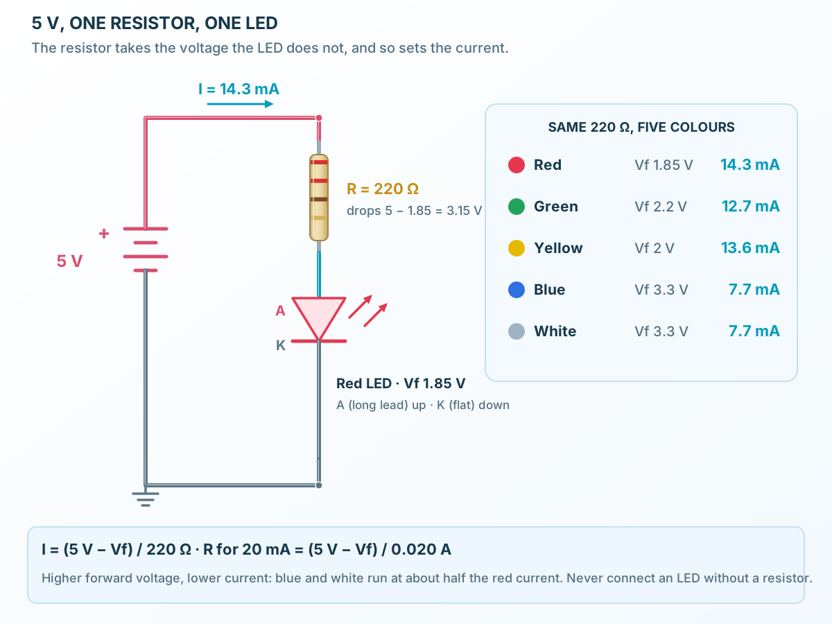
R = (5 V − Vf) / I
Manufacturer specifications 9 parameters
Scroll sideways to see all columns.
| Parameter | Value | Conditions / notes |
|---|---|---|
| Red at 20 mA | 160 Ω (E24) | (5 − 1.85) / 0.020 = 157.5 Ω, next E24 value above |
| Green at 20 mA | 150 Ω (E24) | (5 − 2.2) / 0.020 = 140 Ω, next E24 value above |
| Yellow at 20 mA | 150 Ω (E24) | (5 − 2) / 0.020 = 150 Ω, next E24 value above |
| Blue at 20 mA | 91 Ω (E24) | (5 − 3.3) / 0.020 = 85 Ω, next E24 value above |
| White at 20 mA | 91 Ω (E24) | (5 − 3.3) / 0.020 = 85 Ω, next E24 value above |
| Red with 220 Ω | 14.3 mA | (5 − 1.85) / 220 Ω, typical Vf |
| Green with 220 Ω | 12.7 mA | (5 − 2.2) / 220 Ω, typical Vf |
| Yellow with 220 Ω | 13.6 mA | (5 − 2) / 220 Ω, typical Vf |
| Blue and white with 220 Ω | 7.7 mA | (5 − 3.3) / 220 Ω, typical Vf |
No specifications match. Try a parameter name or a unit.
A microcontroller pin drops a little voltage under load, so the measured current is slightly lower (ProTech’s LED example shows 12.9 mA red, 7.2 mA blue).
Package
WP7113QBC/D · T-1¾ (5 mm)
Manufacturer specifications 5 parameters
Scroll sideways to see all columns.
| Parameter | Value | Conditions / notes |
|---|---|---|
| Lens | Ø5.0 mm | Domed epoxy |
| Flange | Ø5.9 mm, 1.0 mm thick | The flat marks the cathode |
| Height | 8.6 mm | From the flange’s foot to the dome |
| Leads | 0.5 mm square, 2.54 mm apart, 27 mm minimum | Through-hole |
| Footprint | Pads A and K, 2.54 mm apart | 2.032 mm square pads, 1.016 mm drill |
No specifications match. Try a parameter name or a unit.
Mechanical tolerance ±0.25 mm unless the sheet states otherwise.
Connections by function
Select a pin for its function, connection guidance and electrical notes.
Anode · long lead1 pin
Cathode · flat side1 pin
LED (5 mm) at a glance
Follow the labeled connections and functional stages
How it works
3 stages · Explore one step at a time
Forward bias the junction
With the anode more positive than the cathode by about the forward voltage, electrons and holes cross the junction and recombine.
Recombination makes light
Each recombination releases a photon. The band gap of the chip material sets its energy, and so the colour: GaAlAs red, AlGaInP yellow, GaP green, InGaN blue; white adds a phosphor to a blue chip.
Limit the current
Above Vf the current rises exponentially, so a series resistor (or a constant-current driver) must set it. Brightness follows the current; heat follows current × voltage.
Step 1 of 3
LED (5 mm) in a circuit
Supply, series resistor, LED and the return to ground.
Connect it, step by step
Follow the component values and pin connections
Choose the current
10–20 mA for a bright indicator, a few mA for a panel light.
Size the resistor
R = (5 V − Vf) / I; take the next E24 value above.
Mind the polarity
Long lead to the resistor side, short lead and flat to ground.
Inside LED (5 mm)
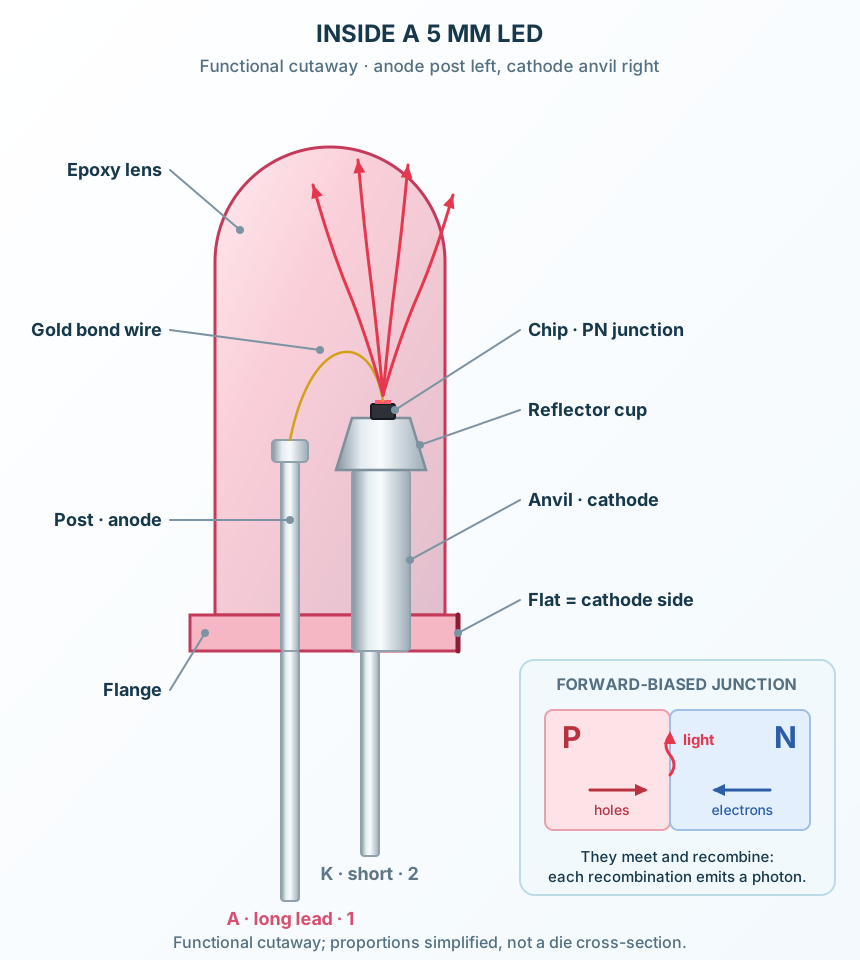
Anvil, post, chip, bond wire and the epoxy lens.
Explore the circuit
Select a stage to see its role and connections
Anvil and reflector cup
The larger internal lead, on the cathode side, carries the chip in a small reflector cup.
Bond wire
A fine gold wire connects the top of the chip to the anode post.
Lens
The domed epoxy lens shapes the beam: a narrow lens gives a small viewing angle and a bright centre.
Selected packageT-1¾ (5 mm)WP7113QBC/D
Physical connections2 pinsPackage-specific numbering
Reference collection7 tables38 parameters & pin functions
Pin reference
Signal names, electrical functions and connection guidance
Physical pin numbers2 pins
Scroll within the table to see all columns and rows.
| Pin | Signal | Type | Function & connection |
|---|---|---|---|
| A | Anode (+) | The longer lead. Conventional current enters here when the LED is forward biased.Connection guidanceConnect to the supply or a microcontroller pin through the series resistor. Forward voltage at 20 mA: 1.85 V red, 2.2 V green, 2.0 V yellow, 3.3 V blue and white (typical). | |
| K | Cathode (−) | The shorter lead, next to the flat on the flange. Current leaves the LED here.Connection guidanceConnect to ground (or to a pin that sinks current). Never more than 5 V reverse: the LED is not a rectifier. |
No pins match these filters. Try another signal name or reset the filters.
Selected family and polarity
Manufacturer scope and page conventions
Manufacturer-referenced values6 parameters
Scroll within the table to see all columns and rows.
| Parameter | Value | Conditions / notes |
|---|---|---|
| Reference family | Kingbright WP7113, 5 mm (T-1¾) | One product specification per colour |
| Parts | WP7113SRC/DU red · SGD green · SYD yellow · QBC/D blue · QWC/D white | One package; the 3D view shows the blue part |
| Anode | Long lead · pin 1 · pad A | Conventional current enters here |
| Cathode | Short lead, flat on the flange · pin 2 · pad K | Connect toward ground |
| Lens | Ø5.0 mm, water clear or diffused by part | Viewing angle 20–30° (2θ½) |
| Lead spacing | 2.54 mm | 0.5 mm square leads |
No specifications match. Try a parameter name or a unit.
Polarity is marked twice: the shorter lead and the flat. Trim the leads only after noting the anode.
The five colours
Typical at 20 mA and 25 °C unless stated
Manufacturer-referenced values5 parameters
Scroll within the table to see all columns and rows.
| Colour | Part | Vf typ / max (V) | IF max (mA) | Peak IF (mA) | PD (mW) | Iv typ (mcd) | λdom (nm) | 2θ½ (°) | Chip |
|---|---|---|---|---|---|---|---|---|---|
| Red | WP7113SRC/DU | 1.85 / 2.5 | 30 | 155 | 75 | 1300 | 640 | 20 | GaAlAs |
| Green | WP7113SGD | 2.2 / 2.5 | 25 | 140 | 62.5 | 40 | 568 | 30 | GaP |
| Yellow | WP7113SYD | 2 / 2.5 | 30 | 150 | 75 | 1200 | 590 | 30 | AlGaInP |
| Blue | WP7113QBC/D | 3.3 / 4 | 30 | 150 | 120 | 4500 | 465 | 20 | InGaN |
| White | WP7113QWC/D | 3.3 / 4 | 30 | 150 | 120 | 3600 | x 0.31, y 0.31 | 20 | InGaN + phosphor |
No specifications match. Try a parameter name or a unit.
Peak IF: 1/10 duty cycle, 0.1 ms pulse. Luminous intensity ±15 %. ProTech’s LED colour presets take exactly these values.
Absolute maximum ratings
At 25 °C · stress limits, not operating conditions
Manufacturer-referenced values7 parameters
Scroll within the table to see all columns and rows.
| Parameter | Value | Conditions / notes |
|---|---|---|
| Continuous forward current | 30 mA (green 25 mA) | Derate above about 25 °C to about 5 mA at 85 °C |
| Peak forward current | 140–155 mA by colour | 1/10 duty cycle, 0.1 ms pulse |
| Power dissipation | 75 mW red and yellow · 62.5 mW green · 120 mW blue and white | PD at 25 °C |
| Reverse voltage | 5 V | IR ≤ 10 µA red, green, yellow; ≤ 50 µA blue, white |
| Junction temperature | 115 °C (green 110 °C) | Maximum |
| Operating and storage temperature | −40 to +85 °C | Ambient |
| Electrostatic discharge (HBM) | 3 kV red, yellow · 8 kV green · 250 V blue, white | Handle InGaN parts with ESD care |
No specifications match. Try a parameter name or a unit.
Exceeding any one of these can damage the LED even if the others are respected.
Electrical and thermal characteristics
Typical unless stated
Manufacturer-referenced values6 parameters
Scroll within the table to see all columns and rows.
| Parameter | Value | Conditions / notes |
|---|---|---|
| Forward voltage temperature coefficient | −1.9 to −2 mV/°C red, green, yellow · −3 mV/°C blue, white | Vf falls as the junction heats |
| Thermal resistance, junction to ambient | 580 red · 590 green, yellow · 610 blue · 570 white °C/W | On FR4 |
| Luminous intensity tolerance | ±15 % | At 20 mA |
| Brightness against current | Roughly proportional | Within the rated current; efficiency falls when hot |
| Reverse current | ≤ 10 µA (red, green, yellow) · ≤ 50 µA (blue, white) | VR = 5 V |
| Self-heating example | 26 mW × 580 °C/W ≈ 15 °C rise | Red at 14.3 mA, 1.85 V |
No specifications match. Try a parameter name or a unit.
Forward voltage spreads between parts of the same colour; never wire LEDs in parallel without a resistor each.
Series resistor from a 5 V pin
R = (5 V − Vf) / I
Manufacturer-referenced values9 parameters
Scroll within the table to see all columns and rows.
| Parameter | Value | Conditions / notes |
|---|---|---|
| Red at 20 mA | 160 Ω (E24) | (5 − 1.85) / 0.020 = 157.5 Ω, next E24 value above |
| Green at 20 mA | 150 Ω (E24) | (5 − 2.2) / 0.020 = 140 Ω, next E24 value above |
| Yellow at 20 mA | 150 Ω (E24) | (5 − 2) / 0.020 = 150 Ω, next E24 value above |
| Blue at 20 mA | 91 Ω (E24) | (5 − 3.3) / 0.020 = 85 Ω, next E24 value above |
| White at 20 mA | 91 Ω (E24) | (5 − 3.3) / 0.020 = 85 Ω, next E24 value above |
| Red with 220 Ω | 14.3 mA | (5 − 1.85) / 220 Ω, typical Vf |
| Green with 220 Ω | 12.7 mA | (5 − 2.2) / 220 Ω, typical Vf |
| Yellow with 220 Ω | 13.6 mA | (5 − 2) / 220 Ω, typical Vf |
| Blue and white with 220 Ω | 7.7 mA | (5 − 3.3) / 220 Ω, typical Vf |
No specifications match. Try a parameter name or a unit.
A microcontroller pin drops a little voltage under load, so the measured current is slightly lower (ProTech’s LED example shows 12.9 mA red, 7.2 mA blue).
Package
WP7113QBC/D · T-1¾ (5 mm)
Manufacturer-referenced values5 parameters
Scroll within the table to see all columns and rows.
| Parameter | Value | Conditions / notes |
|---|---|---|
| Lens | Ø5.0 mm | Domed epoxy |
| Flange | Ø5.9 mm, 1.0 mm thick | The flat marks the cathode |
| Height | 8.6 mm | From the flange’s foot to the dome |
| Leads | 0.5 mm square, 2.54 mm apart, 27 mm minimum | Through-hole |
| Footprint | Pads A and K, 2.54 mm apart | 2.032 mm square pads, 1.016 mm drill |
No specifications match. Try a parameter name or a unit.
Mechanical tolerance ±0.25 mm unless the sheet states otherwise.
No matching rowsTry a pin name, parameter, unit or test condition, or reset the filters.
Status indicators
Power, activity and fault lights on boards and panels, typically at 2–10 mA.
Manufacturer application guideMicrocontroller outputs
A GPIO pin through a resistor: the classic first Arduino circuit. Keep pin current within the board’s limit.
Manufacturer application guideColour signalling
Red, yellow and green for state; blue and white need 3.3 V of headroom, so check the supply.
Manufacturer application guideTake it into ProTech
Find LED (5 mm) in the Components Library to place its schematic symbol and connect its pins.
Reference page · circuit simulation model not yet availableOpen ProTech