 BETA
Set gm independently
IABC A1 and IABC B16 control the two channels separately.
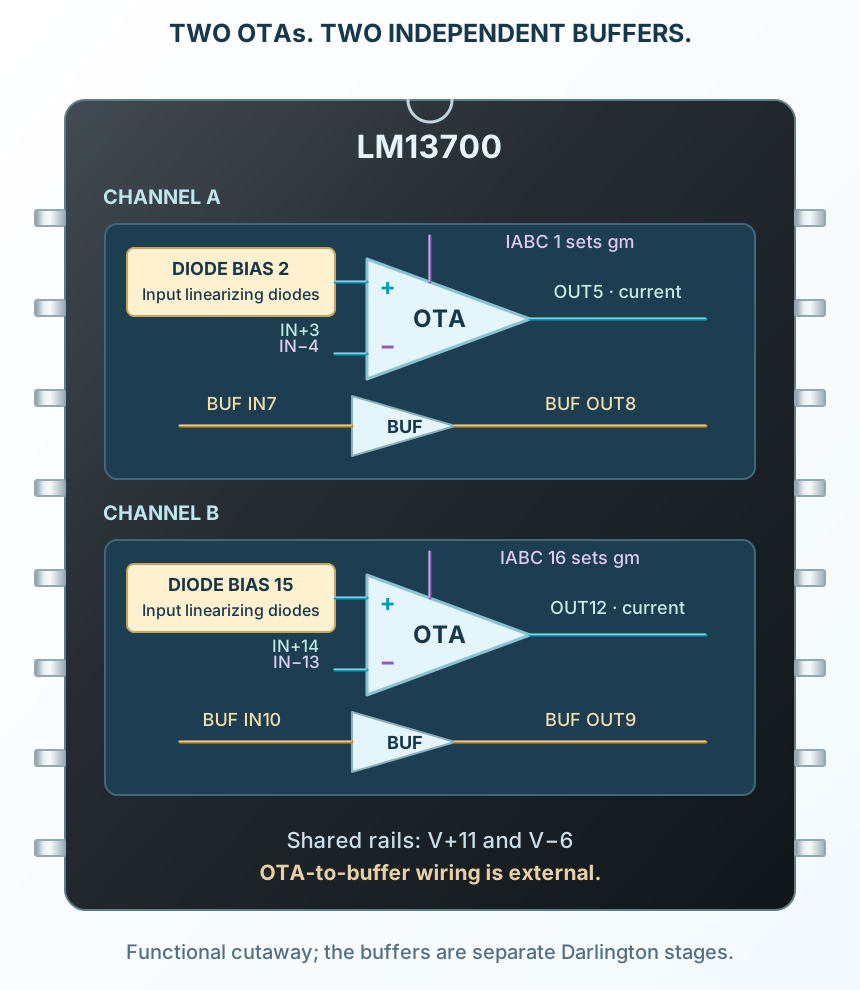
Explore the internal circuitry and functional stages of LM13700.
Two current-output amplifiers and two separate buffers.
Select a stage to see its role and connections
IABC A1 and IABC B16 control the two channels separately.
DIODE A2 and DIODE B15 bias input-linearizing diodes for appropriately conditioned signals.
Use the OTA current output directly, or externally connect and bias its separate buffer.