Real View
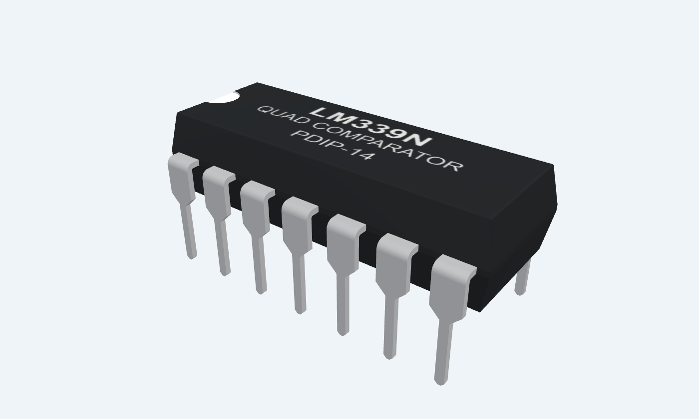
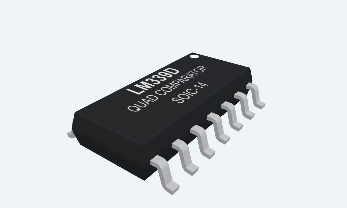
Make four independent voltage decisions in one IC.
LM339 contains four independent voltage comparators in a 14-pin IC. Each compares two input voltages and uses an open-collector output transistor to signal the result. The output can pull a node LOW, but it needs an external pull-up resistor to produce a defined HIGH. The input range includes ground and requires headroom below the positive supply. This page uses the classic LM339N and LM339D, with a 5 V threshold circuit. Pin numbers define every connection; channel 1/2 names can be transposed in other manufacturers’ documents without changing the physical pinout.
Select a pin to explore its connection
Click a lead or use the arrow keys. Top view
Sinks current when IN+ is below IN−. Releases when IN+ is above IN−.
Add a 10 kΩ pull-up to +5 V and connect a high-impedance logic input.
An external pull-up is required for a defined HIGH.
Sinks current when IN+ is below IN−. Releases when IN+ is above IN−.
Leave open when unused.
An external pull-up is required for a defined HIGH.
Shared positive supply for all four comparators.
Use +5 V with 100 nF bypass to pin 12.
Classic LM339: 2–30 V operating range.
Negative input for the comparator whose output is pin 2.
Connect to the 2.0 V reference when unused.
Positive input for the comparator whose output is pin 2.
Connect to GND when unused.
Stay within the common-mode range.
Negative input for the comparator whose output is pin 1.
Connect to the 2.0 V reference.
Positive input for the comparator whose output is pin 1.
Connect to VIN, the adjustable signal.
Stay within the common-mode range.
Negative input for the comparator whose output is pin 14.
Connect to the 2.0 V reference when unused.
Positive input for the comparator whose output is pin 14.
Connect to GND when unused.
Stay within the common-mode range.
Negative input for the comparator whose output is pin 13.
Connect to the 2.0 V reference when unused.
Positive input for the comparator whose output is pin 13.
Connect to GND when unused.
Stay within the common-mode range.
Shared negative supply / ground.
Connect to signal and supply returns.
Sinks current when IN+ is below IN−. Releases when IN+ is above IN−.
Leave open when unused.
An external pull-up is required for a defined HIGH.
Sinks current when IN+ is below IN−. Releases when IN+ is above IN−.
Leave open when unused.
An external pull-up is required for a defined HIGH.
Share the supply and reference, but give each used output its own suitable pull-up. The comparator is a switching device, not a linear op-amp.
LM339N · PDIP-14
| Property | Details |
|---|---|
| Manufacturer | Texas Instruments |
| Part number | LM339N |
| Package | PDIP-14 |
| Connections | 14 pins |
| Mounting | Through-hole |
| Lead pitch | 2.54 mm |
| Package code | dip |
| Thermal reference | Board and package dependent; see manufacturer data |
Classic LM339 · not LM339B
Scroll sideways to see all columns.
| Parameter | Value | Conditions / notes |
|---|---|---|
| Supply | 2–30 V | Single supply |
| Ambient temperature | 0 to 70°C | LM339 grade |
| Input common-mode range | 0 to VCC − 1.5 V | At 25°C |
| Input common-mode range | 0 to VCC − 2 V | Across the full temperature range |
| Total supply current | 0.8 mA typical; 2 mA maximum | Four channels; VO = 2.5 V; no load; 25°C |
No specifications match. Try a parameter name or a unit.
B variants have different supply, offset and temperature limits.
5 V unless stated
Scroll sideways to see all columns.
| Parameter | Value | Conditions / notes |
|---|---|---|
| Input offset | 2 mV typical; 5 mV maximum | At 25°C; specified common-mode condition |
| Input offset across temperature | 9 mV maximum | Classic LM339 |
| Input bias-current magnitude | 25 nA typical; 250 nA maximum | At 25°C |
| Input bias-current magnitude | 400 nA maximum | Across temperature |
| LOW output voltage | 150 mV typical; 400 mV maximum | 4 mA sink; −1 V differential; 25°C |
| LOW output across temperature | 700 mV maximum | 4 mA sink |
| Off-state leakage | 0.1 nA typical; 50 nA maximum | VO = 5 V; 25°C |
| Typical response time | 1.3 µs | 100 mV step; 5 mV overdrive; 5.1 kΩ pull-up; 15 pF |
No specifications match. Try a parameter name or a unit.
Small-signal timing and output voltage depend on overdrive, pull-up, load and temperature.
Physical pin numbers
Scroll sideways to see all columns.
| Parameter | Value | Conditions / notes |
|---|---|---|
| OUT1 pin1 | IN+7 / IN−6 | Used threshold channel |
| OUT2 pin2 | IN+5 / IN−4 | Second independent comparator |
| OUT3 pin14 | IN+9 / IN−8 | Third independent comparator |
| OUT4 pin13 | IN+11 / IN−10 | Fourth independent comparator |
| Shared supply | VCC3 / GND12 | Do not confuse this map with LM324 |
No specifications match. Try a parameter name or a unit.
Some manufacturers swap channel 1 and 2 names. The physical input/output groupings above are unchanged.
5 V · 2 V reference
Scroll sideways to see all columns.
| Parameter | Value | Conditions / notes |
|---|---|---|
| Reference divider | 15 kΩ above, 10 kΩ below | 5 × 10 / (15 + 10) = 2.0 V nominal |
| Signal input | VIN → pin7 | Use 0–3 V for the reviewed full-temperature range |
| Reference input | VREF → pin6 | Same reference also biases unused negative inputs |
| Pull-up | 10 kΩ from output1 to +5 V | Required for logic HIGH |
| Supply bypass | 100 nF from3 to12 | Close to the package |
| Unused comparators | Positive inputs to GND; negative inputs to VREF | Leave their outputs open |
| Below reference | Output LOW | Transistor sinks pull-up current |
| Above reference | Output HIGH through pull-up | Transistor is off |
No specifications match. Try a parameter name or a unit.
Divider accuracy depends on resistor tolerances and input bias. The explorer uses a chosen reference value.
LM339N · PDIP-14
Scroll sideways to see all columns.
| Parameter | Value | Conditions / notes |
|---|---|---|
| Lead pitch | 2.54 mm | Through-hole; top view |
| Supply absolute maximum | 36 V | Classic non-B stress limit |
| Output absolute maximum | 36 V / 20 mA | Stress limits; design within operating conditions |
| Storage temperature | −65 to +150°C | Unpowered |
| Input/output distinction | Outputs can sink; inputs cannot power a load | Use a pull-up sized for the connected logic |
No specifications match. Try a parameter name or a unit.
Output pull-up voltage, input range and supply voltage are separate design constraints.
Select a pin for its function, connection guidance and electrical notes.
Follow the labeled connections and functional stages
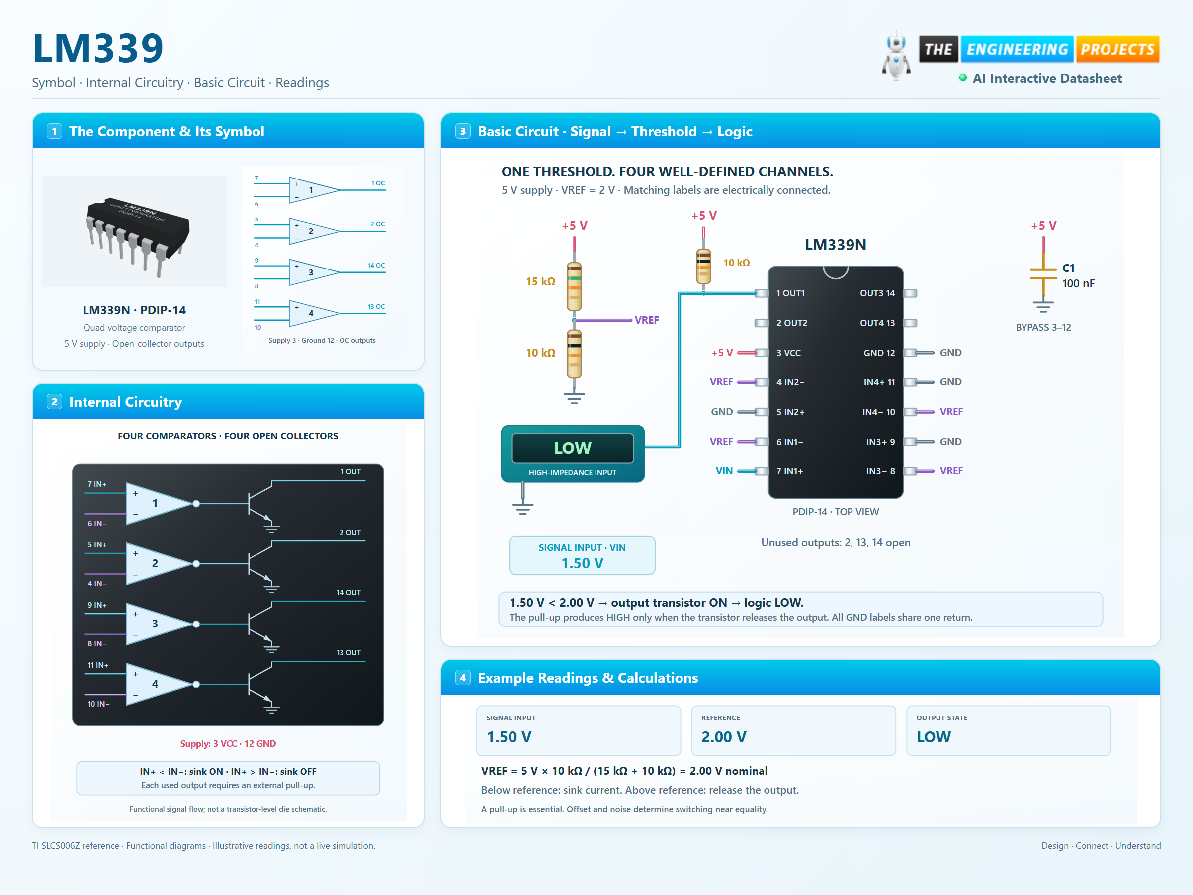
3 stages · Explore one step at a time
Each channel responds to IN+ minus IN−. A sufficiently positive difference releases its output; a negative difference turns the sink transistor on.
An open collector cannot drive HIGH by itself. The pull-up supplies the output node when the transistor is off.
Offset and noise determine the state near the threshold. Add intentional hysteresis when a noisy signal would otherwise cause repeated switching.
Adjust VIN and the reference. Remove the pull-up to see why it matters.
Enable JavaScript to explore the comparator.
Violet: offset-sensitive transition · Amber: input outside the recommended range.
DC teaching model for one classic LM339 channel. The ±9 mV region illustrates possible offset, not built-in hysteresis. A fixed 0.15 V LOW is illustrative; real output voltage depends on sink current and temperature. Timing and noise are not simulated.
A 2 V reference, a pull-up and all unused inputs defined.
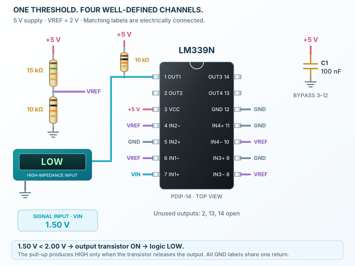
Follow the component values and pin connections
The resistor divider makes 2.0 V nominal from 5 V.
Read the output with a high-impedance logic input or meter.
Bias unused channels away from equality and leave their outputs open.
Four differential comparators, each with an open collector.
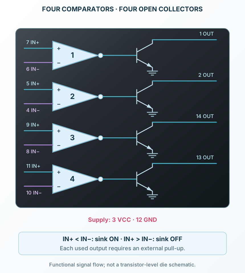
Select a stage to see its role and connections
The input stage responds to the difference between the two voltages.
The output transistor either sinks current or releases the node.
Each comparator has separate inputs and output, with a common supply.
Signal names, electrical functions and connection guidance
Scroll within the table to see all columns and rows.
| Pin | Signal | Type | Function & connection |
|---|---|---|---|
| OUT1 | Open-collector output | Sinks current when IN+ is below IN−. Releases when IN+ is above IN−.Connection guidanceAdd a 10 kΩ pull-up to +5 V and connect a high-impedance logic input. An external pull-up is required for a defined HIGH. | |
| OUT2 | Open-collector output | Sinks current when IN+ is below IN−. Releases when IN+ is above IN−.Connection guidanceLeave open when unused. An external pull-up is required for a defined HIGH. | |
| VCC | Positive supply | Shared positive supply for all four comparators.Connection guidanceUse +5 V with 100 nF bypass to pin 12. Classic LM339: 2–30 V operating range. | |
| IN2− | Inverting input | Negative input for the comparator whose output is pin 2.Connection guidanceConnect to the 2.0 V reference when unused. | |
| IN2+ | Non-inverting input | Positive input for the comparator whose output is pin 2.Connection guidanceConnect to GND when unused. Stay within the common-mode range. | |
| IN1− | Inverting input | Negative input for the comparator whose output is pin 1.Connection guidanceConnect to the 2.0 V reference. | |
| IN1+ | Non-inverting input | Positive input for the comparator whose output is pin 1.Connection guidanceConnect to VIN, the adjustable signal. Stay within the common-mode range. | |
| IN3− | Inverting input | Negative input for the comparator whose output is pin 14.Connection guidanceConnect to the 2.0 V reference when unused. | |
| IN3+ | Non-inverting input | Positive input for the comparator whose output is pin 14.Connection guidanceConnect to GND when unused. Stay within the common-mode range. | |
| IN4− | Inverting input | Negative input for the comparator whose output is pin 13.Connection guidanceConnect to the 2.0 V reference when unused. | |
| IN4+ | Non-inverting input | Positive input for the comparator whose output is pin 13.Connection guidanceConnect to GND when unused. Stay within the common-mode range. | |
| GND | Supply return | Shared negative supply / ground.Connection guidanceConnect to signal and supply returns. | |
| OUT4 | Open-collector output | Sinks current when IN+ is below IN−. Releases when IN+ is above IN−.Connection guidanceLeave open when unused. An external pull-up is required for a defined HIGH. | |
| OUT3 | Open-collector output | Sinks current when IN+ is below IN−. Releases when IN+ is above IN−.Connection guidanceLeave open when unused. An external pull-up is required for a defined HIGH. |
No pins match these filters. Try another signal name or reset the filters.
Classic LM339 · not LM339B
Scroll within the table to see all columns and rows.
| Parameter | Value | Conditions / notes |
|---|---|---|
| Supply | 2–30 V | Single supply |
| Ambient temperature | 0 to 70°C | LM339 grade |
| Input common-mode range | 0 to VCC − 1.5 V | At 25°C |
| Input common-mode range | 0 to VCC − 2 V | Across the full temperature range |
| Total supply current | 0.8 mA typical; 2 mA maximum | Four channels; VO = 2.5 V; no load; 25°C |
No specifications match. Try a parameter name or a unit.
B variants have different supply, offset and temperature limits.
5 V unless stated
Scroll within the table to see all columns and rows.
| Parameter | Value | Conditions / notes |
|---|---|---|
| Input offset | 2 mV typical; 5 mV maximum | At 25°C; specified common-mode condition |
| Input offset across temperature | 9 mV maximum | Classic LM339 |
| Input bias-current magnitude | 25 nA typical; 250 nA maximum | At 25°C |
| Input bias-current magnitude | 400 nA maximum | Across temperature |
| LOW output voltage | 150 mV typical; 400 mV maximum | 4 mA sink; −1 V differential; 25°C |
| LOW output across temperature | 700 mV maximum | 4 mA sink |
| Off-state leakage | 0.1 nA typical; 50 nA maximum | VO = 5 V; 25°C |
| Typical response time | 1.3 µs | 100 mV step; 5 mV overdrive; 5.1 kΩ pull-up; 15 pF |
No specifications match. Try a parameter name or a unit.
Small-signal timing and output voltage depend on overdrive, pull-up, load and temperature.
Physical pin numbers
Scroll within the table to see all columns and rows.
| Parameter | Value | Conditions / notes |
|---|---|---|
| OUT1 pin1 | IN+7 / IN−6 | Used threshold channel |
| OUT2 pin2 | IN+5 / IN−4 | Second independent comparator |
| OUT3 pin14 | IN+9 / IN−8 | Third independent comparator |
| OUT4 pin13 | IN+11 / IN−10 | Fourth independent comparator |
| Shared supply | VCC3 / GND12 | Do not confuse this map with LM324 |
No specifications match. Try a parameter name or a unit.
Some manufacturers swap channel 1 and 2 names. The physical input/output groupings above are unchanged.
5 V · 2 V reference
Scroll within the table to see all columns and rows.
| Parameter | Value | Conditions / notes |
|---|---|---|
| Reference divider | 15 kΩ above, 10 kΩ below | 5 × 10 / (15 + 10) = 2.0 V nominal |
| Signal input | VIN → pin7 | Use 0–3 V for the reviewed full-temperature range |
| Reference input | VREF → pin6 | Same reference also biases unused negative inputs |
| Pull-up | 10 kΩ from output1 to +5 V | Required for logic HIGH |
| Supply bypass | 100 nF from3 to12 | Close to the package |
| Unused comparators | Positive inputs to GND; negative inputs to VREF | Leave their outputs open |
| Below reference | Output LOW | Transistor sinks pull-up current |
| Above reference | Output HIGH through pull-up | Transistor is off |
No specifications match. Try a parameter name or a unit.
Divider accuracy depends on resistor tolerances and input bias. The explorer uses a chosen reference value.
LM339N · PDIP-14
Scroll within the table to see all columns and rows.
| Parameter | Value | Conditions / notes |
|---|---|---|
| Lead pitch | 2.54 mm | Through-hole; top view |
| Supply absolute maximum | 36 V | Classic non-B stress limit |
| Output absolute maximum | 36 V / 20 mA | Stress limits; design within operating conditions |
| Storage temperature | −65 to +150°C | Unpowered |
| Input/output distinction | Outputs can sink; inputs cannot power a load | Use a pull-up sized for the connected logic |
No specifications match. Try a parameter name or a unit.
Output pull-up voltage, input range and supply voltage are separate design constraints.
No matching rowsTry a pin name, parameter, unit or test condition, or reset the filters.
Compare sensor voltages with selected references for warning or control outputs.
Manufacturer application guideUse two comparators to identify whether a signal is inside a voltage band.
Manufacturer application guideFour comparators can compare one signal with four reference levels; each used output needs suitable loading.
Manufacturer application guideFind LM339 in the Components Library to place its schematic symbol and connect its pins.
Reference page · circuit simulation model not yet availableOpen ProTech