 BETA
LM386 Working Principle
Learn how LM386 works with an illustrated explanation and practical readings.
LM386 at a glance
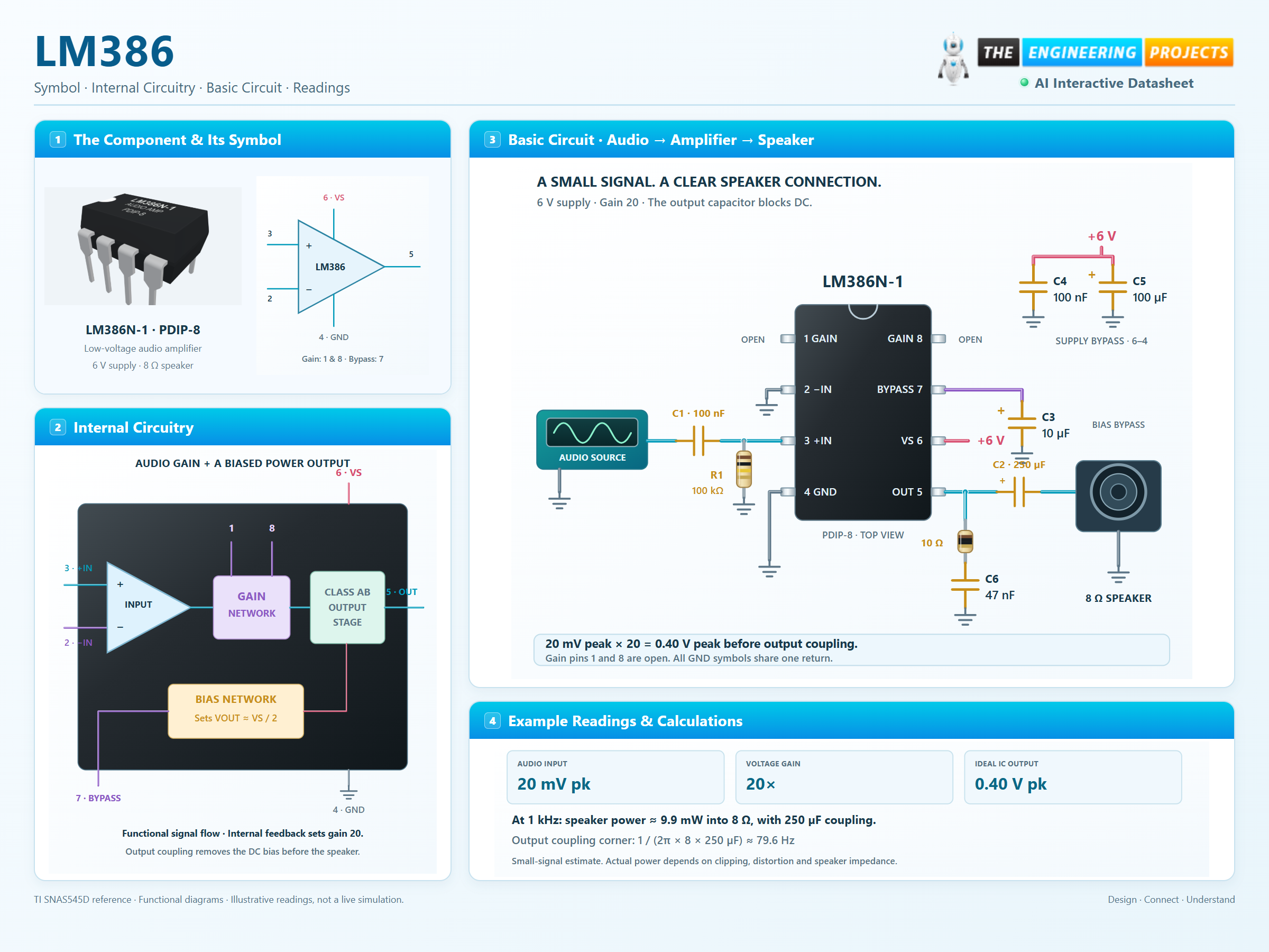
Follow the labeled connections and functional stages
How it works
3 stages · Explore one step at a time
Feed a ground-referenced signal
The input stage accepts a small audio waveform around ground. Coupling and volume control keep the applied level appropriate.
Set the AC gain
Internal feedback sets gain 20. Bypassing the gain network with a capacitor between pins 1 and 8 increases gain; higher gain also amplifies noise.
Remove the DC before the speaker
The output rests near half the supply. A large series capacitor blocks this DC level while passing the changing audio signal.
From millivolts to speaker power
Change gain and frequency to explore amplification and output coupling.
Enable JavaScript to explore audio gain.
Teaching model: ideal gain, an RC output coupling network and an illustrative ±2 V peak output limit. The limit is not a guaranteed LM386 clipping specification. Speaker impedance, bandwidth, noise, distortion and thermal effects are not simulated.