 BETA
LM393 Working Principle
Learn how LM393 works with an illustrated explanation and practical readings.
LM393 at a glance
Follow the labeled connections and functional stages
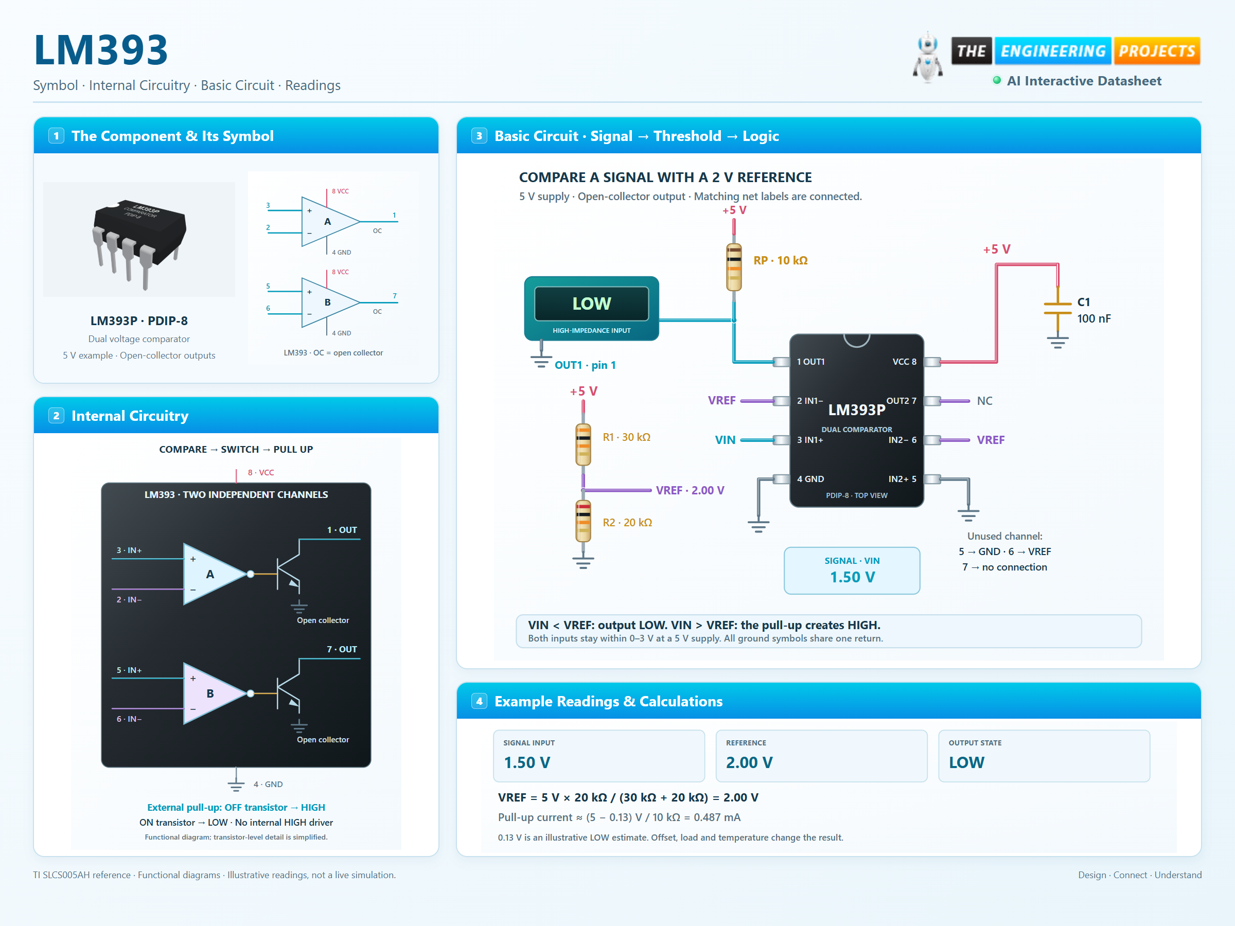
How it works
3 stages · Explore one step at a time
Compare the two inputs
The differential input stage responds to IN+ minus IN−. No analog-to-digital converter or firmware is needed.
Sink current or release the node
A negative input difference turns the output transistor on. A positive difference turns it off. The external pull-up supplies the HIGH level.
Make a stable decision
Keep inputs in their common-mode range. Add positive-feedback hysteresis when a slowly changing or noisy signal would chatter around the threshold.
Find the switching threshold
Adjust VIN and the reference. Remove the pull-up to see why it matters.
Enable JavaScript to explore the comparator.
Violet: offset-sensitive transition · Amber: input outside the recommended range.
DC teaching model for channel A. The ±9 mV band uses the maximum input-offset magnitude over 0–70°C; it is uncertainty, not hysteresis. LOW uses a 0.13 V illustrative estimate. Propagation delay, input bias, leakage and noise are omitted.