Real View
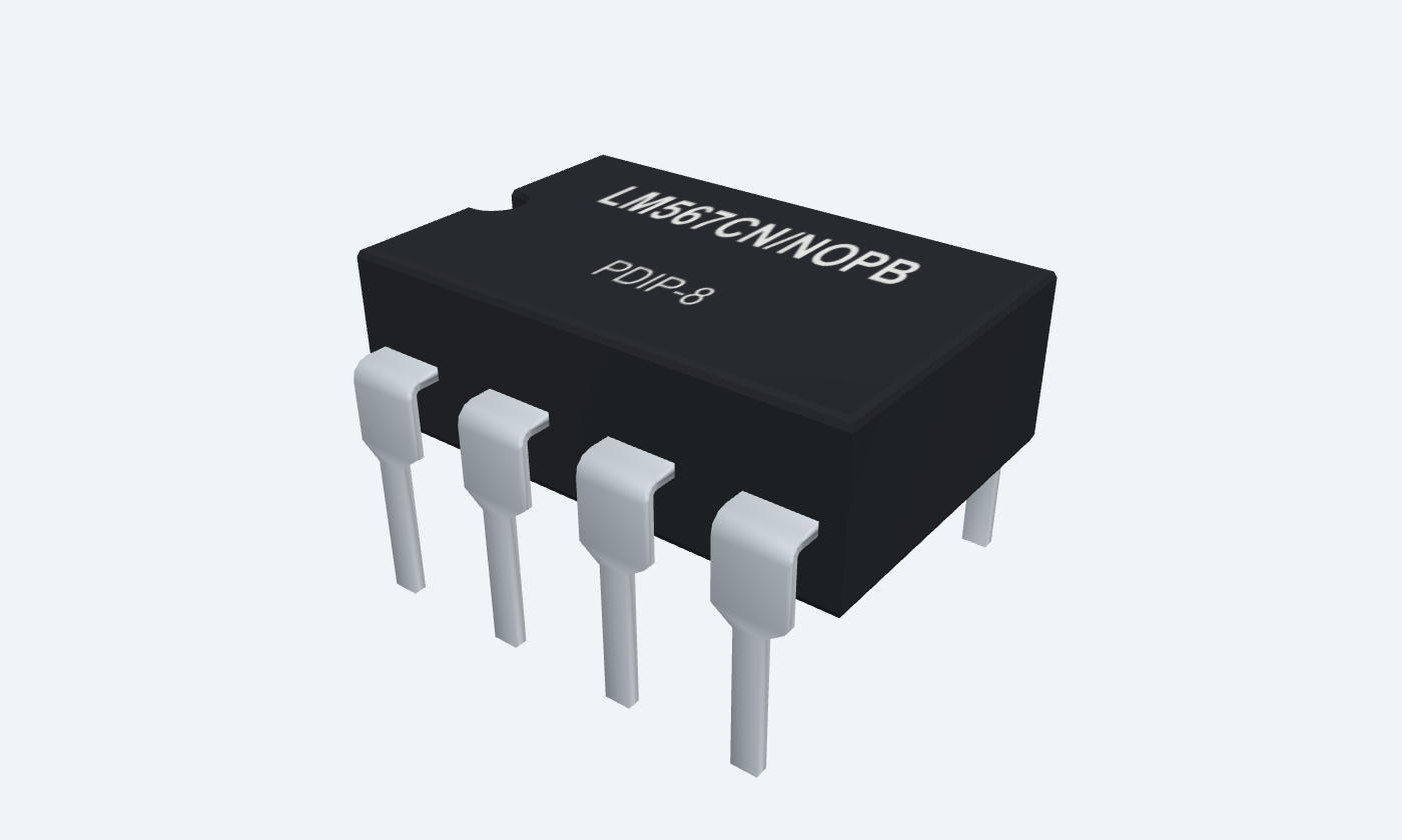
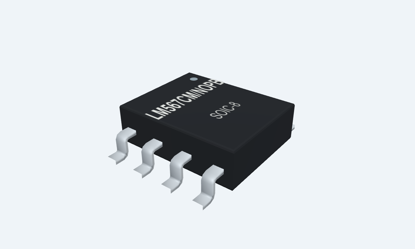
Recognize a tone and turn it into a clear logic signal.
LM567C uses a phase-locked loop to recognize a tone near an externally selected frequency. When a sufficiently strong signal lies inside its detection band, an internal output transistor turns on and pulls OUT low. A pull-up resistor supplies the released HIGH state. A resistor between pins 5 and 6 and a capacitor from pin 6 to ground set the nominal center frequency. Separate capacitors at pins 2 and 1 set loop filtering and output response; they do not replace the timing capacitor. This page covers the LM567CN/NOPB and LM567CM/NOPB commercial parts, rated from 0 to 70°C. The illustrated 5 V circuit uses 10 kΩ and 100 nF for approximately 909 Hz. Component tolerances, signal amplitude, filters and settling determine actual detection.
Select a pin to explore its connection
Click a lead or use the arrow keys. Top view
Sets output filtering and detection delay.
Connect 2.2 µF to ground; positive end at pin 1.
Use C3 at least twice the loop-filter capacitor in the illustrated design.
Filters the phase-locked-loop control signal.
Connect 1 µF to ground; positive end at pin 2.
This capacitor affects capture bandwidth and response time.
Accepts the tone to be detected.
Feed the grounded signal generator through a 100 nF series capacitor.
Use 100 mV RMS near 909 Hz for this example, not a rail-level digital signal.
Powers the decoder circuitry.
Connect regulated +5 V, with 100 nF and 1 µF local bypass to ground.
One side of the oscillator timing resistor.
Connect R1 = 10 kΩ between pins 5 and 6.
The resistor goes between these pins, not from pin 5 to VCC.
Oscillator timing node.
Connect C1 = 100 nF to ground, and the other end of R1 from pin 5.
Use stable timing parts and short traces.
Common supply and signal return.
Join supply negative, filter returns and signal-generator ground.
Sinks current when a sufficient signal is detected in the passband.
Add a 10 kΩ pull-up to +5 V and read with a high-impedance meter.
LOW means detected. Without the pull-up, the released output is not driven HIGH.
The oscillator and phase detectors track an input near the selected center. External filters determine how quickly and selectively the output responds.
LM567CN/NOPB · PDIP-8
| Property | Details |
|---|---|
| Manufacturer | Texas Instruments |
| Part number | LM567CN/NOPB |
| Package | PDIP-8 |
| Connections | 8 pins |
| Mounting | Through-hole |
| Lead pitch | 2.54 mm |
| Package code | dip |
| Thermal reference | θJA 53.0°C/W · manufacturer thermal table |
LM567C · 5 V / 25°C electrical tests
Scroll sideways to see all columns.
| Parameter | Value | Conditions / notes |
|---|---|---|
| Operating supply | 3.5–8.5 V | Recommended operating table; use 5 V for the example |
| Selected ambient | 0 to +70°C | CN / CM ordering options |
| Quiescent supply current | 7 mA typical; 10 mA maximum | RL = 20 kΩ |
| Activated supply current | 12 mA typical; 15 mA maximum | RL = 20 kΩ |
| Input resistance | 15 kΩ minimum; 20 kΩ typical | Tone input pin 3 |
| Smallest detected input | 20 mV RMS typical; 25 mV RMS maximum | Input at center frequency; manufacturer IL = 100 mA condition |
No specifications match. Try a parameter name or a unit.
Detection depends on frequency, amplitude, filtering and the manufacturer test conditions.
External components define the application
Scroll sideways to see all columns.
| Parameter | Value | Conditions / notes |
|---|---|---|
| Approximate center frequency | 1 / (1.1 × R1 × C1) | R in ohms; C in farads; result in hertz |
| Timing resistor | Pins 5 to 6 | 10 kΩ in the example |
| Timing capacitor | Pin 6 to ground | 100 nF in the example |
| Highest center frequency | 100 kHz minimum; 500 kHz typical | 500 kHz is not a guaranteed limit for every unit |
| Largest detection bandwidth | 14% typical; 10–18% limits | Maximum-setting test; not the width of every filter network |
| Fastest on/off cycling | f₀ / 20 typical | Reference condition, not instantaneous detection |
No specifications match. Try a parameter name or a unit.
R/C tolerance shifts the center; filter values and signal amplitude determine the usable detection band.
Pin 8 sinks current on detection
Scroll sideways to see all columns.
| Parameter | Value | Conditions / notes |
|---|---|---|
| Output LOW at 30 mA | 0.2 V typical; 0.4 V maximum | 25 mV test input |
| Output LOW at 100 mA | 0.6 V typical; 1.0 V maximum | 25 mV test input |
| Output leakage | 0.01 µA typical; 25 µA maximum | Output at 15 V |
| Output rise / fall time | 150 ns / 30 ns typical | Electrical test circuit |
| Example pull-up | 10 kΩ to +5 V | Less than 0.5 mA when LOW |
| Released output | HIGH through the pull-up | The IC does not actively source that HIGH voltage |
No specifications match. Try a parameter name or a unit.
Large sink currents increase power dissipation; the lightly loaded example avoids that condition.
Grounded signal generator and regulated 5 V
Scroll sideways to see all columns.
| Parameter | Value | Conditions / notes |
|---|---|---|
| Input tone | 100 mV RMS near 909 Hz | AC-coupled through 100 nF to pin 3 |
| R1 / C1 | 10 kΩ / 100 nF | R1: 5–6; C1: 6–ground |
| C2 loop filter | 1 µF | Pin 2 to ground; positive at the pin |
| C3 output filter | 2.2 µF | Pin 1 to ground; at least 2 × C2 |
| Supply bypass | 100 nF + 1 µF | Across pins 4 and 7, near the package |
| Output reading | LOW after detection settles | High-impedance meter on pin 8 |
| Nominal arithmetic | 909.1 Hz | 1 / (1.1 × 10000 × 100 × 10⁻⁹) |
No specifications match. Try a parameter name or a unit.
This is an illustrative tuned detector, not a specified instrument. Sweep and calibrate the assembled circuit.
LM567CN/NOPB · PDIP-8
Scroll sideways to see all columns.
| Parameter | Value | Conditions / notes |
|---|---|---|
| Pitch / mounting | 2.54 mm | Through-hole |
| Package numbering | 8 physical pins | Top view; counterclockwise from the marker |
| Supply stress limit | 9 V absolute maximum | Do not confuse with 8.5 V recommended maximum |
| Output stress limit | 15 V at pin 8 | External collector voltage; observe dissipation |
| Storage | −65 to +150°C | Unpowered |
| Layout | Short timing and filter returns | Separate output-load currents from the sensitive input path |
No specifications match. Try a parameter name or a unit.
Absolute ratings are stress boundaries. The downloadable land pattern must be checked against the chosen assembly process.
Select a pin for its function, connection guidance and electrical notes.
Follow the labeled connections and functional stages
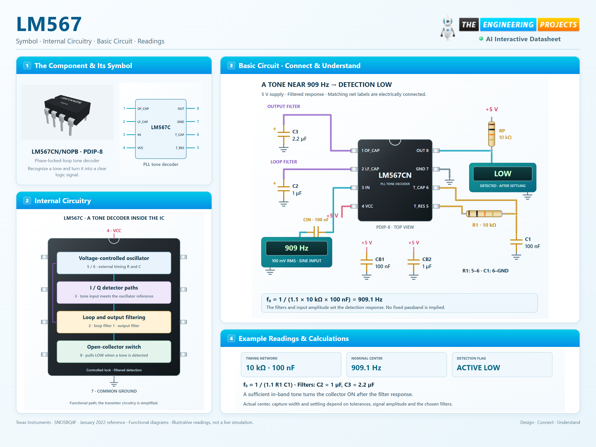
3 stages · Explore one step at a time
Use f₀ ≈ 1 / (1.1 × R1 × C1). With 10 kΩ and 100 nF, the nominal center is 909.1 Hz.
The 1 µF loop capacitor and 2.2 µF output capacitor reduce unwanted responses. Larger filter capacitance generally trades faster response for stronger filtering.
A settled, sufficient tone near the center turns the output transistor on. The 10 kΩ pull-up limits sink current to less than 0.5 mA at 5 V. Out of band, it releases the output.
A physical eight-pin decoder with a complete timing and filter network.
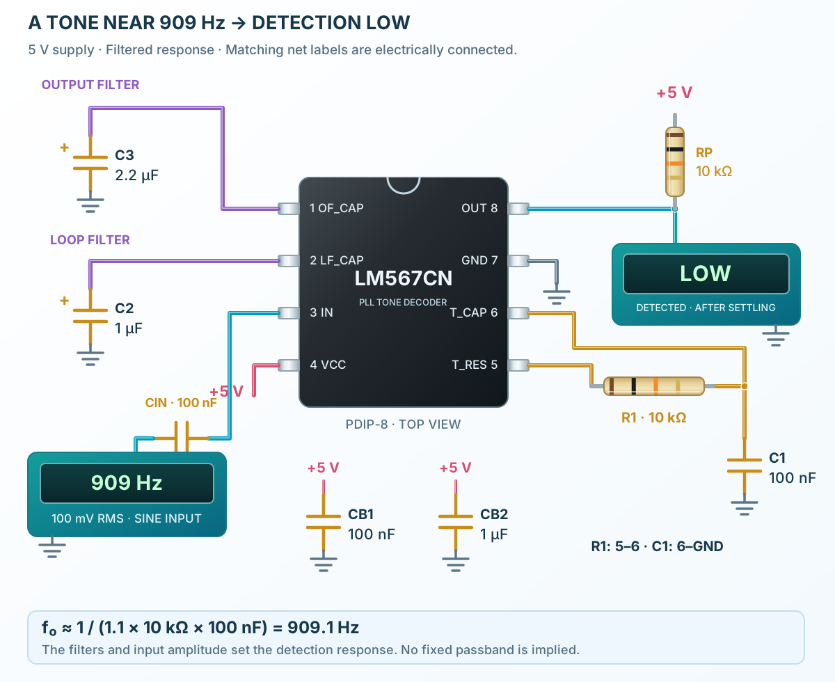
Follow the component values and pin connections
R1 joins pins 5 and 6; C1 joins pin 6 to ground.
Fit C2 at pin 2, C3 at pin 1 and both bypass capacitors across the 5 V supply.
Use a grounded signal generator, start near 909 Hz and observe the active-LOW output after settling.
Oscillator, phase detection and a filtered output in one compact IC.
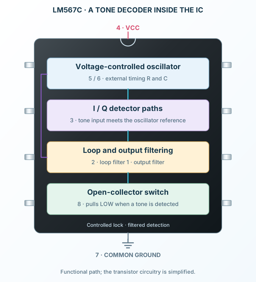
Select a stage to see its role and connections
R1 and C1 set the VCO timing near the desired tone.
I/Q detector paths identify the signal and close the filtered control loop.
The output filter controls the detection response before the transistor sinks pin 8.
Signal names, electrical functions and connection guidance
Scroll within the table to see all columns and rows.
| Pin | Signal | Type | Function & connection |
|---|---|---|---|
| OF_CAP | Output filter | Sets output filtering and detection delay.Connection guidanceConnect 2.2 µF to ground; positive end at pin 1. Use C3 at least twice the loop-filter capacitor in the illustrated design. | |
| LF_CAP | Loop filter | Filters the phase-locked-loop control signal.Connection guidanceConnect 1 µF to ground; positive end at pin 2. This capacitor affects capture bandwidth and response time. | |
| IN | Analog tone input | Accepts the tone to be detected.Connection guidanceFeed the grounded signal generator through a 100 nF series capacitor. Use 100 mV RMS near 909 Hz for this example, not a rail-level digital signal. | |
| VCC | Positive supply | Powers the decoder circuitry.Connection guidanceConnect regulated +5 V, with 100 nF and 1 µF local bypass to ground. | |
| T_RES | Timing resistor | One side of the oscillator timing resistor.Connection guidanceConnect R1 = 10 kΩ between pins 5 and 6. The resistor goes between these pins, not from pin 5 to VCC. | |
| T_CAP | Timing capacitor | Oscillator timing node.Connection guidanceConnect C1 = 100 nF to ground, and the other end of R1 from pin 5. Use stable timing parts and short traces. | |
| GND | Ground return | Common supply and signal return.Connection guidanceJoin supply negative, filter returns and signal-generator ground. | |
| OUT | Open-collector output | Sinks current when a sufficient signal is detected in the passband.Connection guidanceAdd a 10 kΩ pull-up to +5 V and read with a high-impedance meter. LOW means detected. Without the pull-up, the released output is not driven HIGH. |
No pins match these filters. Try another signal name or reset the filters.
LM567C · 5 V / 25°C electrical tests
Scroll within the table to see all columns and rows.
| Parameter | Value | Conditions / notes |
|---|---|---|
| Operating supply | 3.5–8.5 V | Recommended operating table; use 5 V for the example |
| Selected ambient | 0 to +70°C | CN / CM ordering options |
| Quiescent supply current | 7 mA typical; 10 mA maximum | RL = 20 kΩ |
| Activated supply current | 12 mA typical; 15 mA maximum | RL = 20 kΩ |
| Input resistance | 15 kΩ minimum; 20 kΩ typical | Tone input pin 3 |
| Smallest detected input | 20 mV RMS typical; 25 mV RMS maximum | Input at center frequency; manufacturer IL = 100 mA condition |
No specifications match. Try a parameter name or a unit.
Detection depends on frequency, amplitude, filtering and the manufacturer test conditions.
External components define the application
Scroll within the table to see all columns and rows.
| Parameter | Value | Conditions / notes |
|---|---|---|
| Approximate center frequency | 1 / (1.1 × R1 × C1) | R in ohms; C in farads; result in hertz |
| Timing resistor | Pins 5 to 6 | 10 kΩ in the example |
| Timing capacitor | Pin 6 to ground | 100 nF in the example |
| Highest center frequency | 100 kHz minimum; 500 kHz typical | 500 kHz is not a guaranteed limit for every unit |
| Largest detection bandwidth | 14% typical; 10–18% limits | Maximum-setting test; not the width of every filter network |
| Fastest on/off cycling | f₀ / 20 typical | Reference condition, not instantaneous detection |
No specifications match. Try a parameter name or a unit.
R/C tolerance shifts the center; filter values and signal amplitude determine the usable detection band.
Pin 8 sinks current on detection
Scroll within the table to see all columns and rows.
| Parameter | Value | Conditions / notes |
|---|---|---|
| Output LOW at 30 mA | 0.2 V typical; 0.4 V maximum | 25 mV test input |
| Output LOW at 100 mA | 0.6 V typical; 1.0 V maximum | 25 mV test input |
| Output leakage | 0.01 µA typical; 25 µA maximum | Output at 15 V |
| Output rise / fall time | 150 ns / 30 ns typical | Electrical test circuit |
| Example pull-up | 10 kΩ to +5 V | Less than 0.5 mA when LOW |
| Released output | HIGH through the pull-up | The IC does not actively source that HIGH voltage |
No specifications match. Try a parameter name or a unit.
Large sink currents increase power dissipation; the lightly loaded example avoids that condition.
Grounded signal generator and regulated 5 V
Scroll within the table to see all columns and rows.
| Parameter | Value | Conditions / notes |
|---|---|---|
| Input tone | 100 mV RMS near 909 Hz | AC-coupled through 100 nF to pin 3 |
| R1 / C1 | 10 kΩ / 100 nF | R1: 5–6; C1: 6–ground |
| C2 loop filter | 1 µF | Pin 2 to ground; positive at the pin |
| C3 output filter | 2.2 µF | Pin 1 to ground; at least 2 × C2 |
| Supply bypass | 100 nF + 1 µF | Across pins 4 and 7, near the package |
| Output reading | LOW after detection settles | High-impedance meter on pin 8 |
| Nominal arithmetic | 909.1 Hz | 1 / (1.1 × 10000 × 100 × 10⁻⁹) |
No specifications match. Try a parameter name or a unit.
This is an illustrative tuned detector, not a specified instrument. Sweep and calibrate the assembled circuit.
LM567CN/NOPB · PDIP-8
Scroll within the table to see all columns and rows.
| Parameter | Value | Conditions / notes |
|---|---|---|
| Pitch / mounting | 2.54 mm | Through-hole |
| Package numbering | 8 physical pins | Top view; counterclockwise from the marker |
| Supply stress limit | 9 V absolute maximum | Do not confuse with 8.5 V recommended maximum |
| Output stress limit | 15 V at pin 8 | External collector voltage; observe dissipation |
| Storage | −65 to +150°C | Unpowered |
| Layout | Short timing and filter returns | Separate output-load currents from the sensitive input path |
No specifications match. Try a parameter name or a unit.
Absolute ratings are stress boundaries. The downloadable land pattern must be checked against the chosen assembly process.
No matching rowsTry a pin name, parameter, unit or test condition, or reset the filters.
Detect a known audio tone and provide a logic flag after the filtering delay.
Manufacturer application guideMonitor whether a signal lies near a calibrated center frequency.
Manufacturer application guideUse separately tuned channels for distinct tones, with attention to interference and filter response.
Manufacturer application guideFind LM567 in the Components Library to place its schematic symbol and connect its pins.
Reference page · circuit simulation model not yet availableOpen ProTech