LP2950-3.3100 mA low-dropout fixed regulator
A quiet 3.3 V rail with very little standby current.
LP2950-3.3 is a three-terminal low-dropout regulator for a fixed 3.3 V rail, supplying up to 100 mA when input headroom and temperature permit. The low ground current at light load makes it useful for modest battery-powered analog and digital circuits. This page covers TI C-grade LP2950CZ-3.3/NOPB in TO-92 and LP2950CDT-3.3/NOPB in TO-252. Their OUT and IN pin numbers are reversed: TO-92 uses OUT1/GND2/IN3, while TO-252 uses IN1/GND2/OUT3 with a grounded tab. All package views follow that selection. A suitable output capacitor is essential for stability. The illustrated 5 V to 3.3 V supply uses local 1 µF input bypass, a 10 µF output capacitor with verified ESR, and a 330 Ω test load. The related LP2951 adds control functions; the three-pin LP2950 has no shutdown or error output.
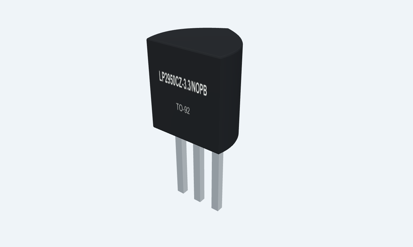
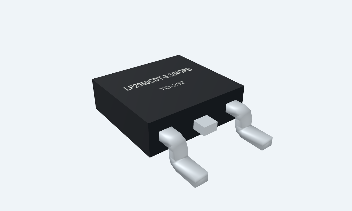

3Physical pins
LP2950CZ-3.3/NOPBTO-92
Manufacturer-referencedTexas Instruments
Pin diagram
Select a pin to explore its connection
Highlight
LP2950-3.3TO-92Front view · flat face toward you · 1 OUT, 2 GND, 3 IN
LP2950-3.3TO-252Front view · leads down · 1 IN, 2 GND, 3 OUT; tab GND
Click a lead or use the arrow keys. Front view · flat face toward you · 1 OUT, 2 GND, 3 IN
PIN 1 · Regulated output
Regulated railOUT
Function
Fixed 3.3 V output; an external stability capacitor is required.
How to connect
Connect to the load and 10 µF output capacitor; return both to GND.
Electrical note
TO-92 pin 1; TO-252 pin 3. Use the selected package map.
PIN 2 · Ground
Common returnGND
Function
Reference and bias-current return for the regulator.
How to connect
Join input return, output capacitor and load grounds locally.
Electrical note
Pin 2 in both packages; TO-252 exposed tab is also GND.
PIN 3 · Supply
Supply inputIN
Function
Supply input for the protected series-pass stage.
How to connect
Use +5 V in the example and local 1 µF bypass.
Electrical note
TO-92 pin 3; TO-252 pin 1. Maximum operating input 30 V; allow design margin.
Key specifications
An internal reference and feedback divider control a series-pass stage. Output capacitance, headroom and ground current remain part of the design.
Fixed output3.3 V · C grade, ±1% at 25°C
Output class100 mA · thermally limited
Light-load ground current75 µA typical at 100 µA load
Junction range−40–125 °C recommended
Package details
LP2950CZ-3.3/NOPB · TO-92
| Property | Details |
|---|---|
| Manufacturer | Texas Instruments |
| Part number | LP2950CZ-3.3/NOPB |
| Package | TO-92 |
| Connections | 3 pins |
| Mounting | Through-hole |
| Lead pitch | 1.27 mm · straight leads |
| Package code | LP |
| Thermal reference | θJA 157.4°C/W under TI board conditions; actual mounting changes temperature rise |
Device and package identity
C-grade fixed 3.3 V parts
Manufacturer specifications 6 parameters
Scroll sideways to see all columns.
| Parameter | Value | Conditions / notes |
|---|---|---|
| Through-hole order | LP2950CZ-3.3/NOPB | TO-92 LP; straight-lead bulk footprint |
| SMD order | LP2950CDT-3.3/NOPB | TO-252 NDP; formed outer leads and grounded tab |
| TO-92 physical pins | OUT1 · GND2 · IN3 | Flat face toward viewer, leads down |
| TO-252 physical pins | IN1 · GND2 · OUT3 | Front face, leads down; tab is GND |
| Accuracy grade | C: ±1% initial | AC-grade values are not substituted |
| Extra controls | No shutdown or error-output lead | These belong to the related LP2951 |
No specifications match. Try a parameter name or a unit.
Verify order suffix and lead form before fabrication.
Operating ranges and stress limits
Temperature and headroom remain essential
Manufacturer specifications 6 parameters
Scroll sideways to see all columns.
| Parameter | Value | Conditions / notes |
|---|---|---|
| Nominal output | 3.3 V | Fixed internally; no external divider |
| Recommended input range | 2.3–30 V family range | 3.3 V regulation additionally needs dropout headroom |
| Maximum input stress | 30 V | Do not design at the stress limit |
| Output-current class | 100 mA | Adequate voltage headroom and cooling required |
| Junction operating temperature | −40–125°C | Device junction, not ambient |
| Minimum external load | Not required for LP2950 regulation | Capacitor stability requirements still apply |
No specifications match. Try a parameter name or a unit.
A 2.3 V input cannot produce a regulated 3.3 V output.
C-grade output accuracy
3.3 V option; source conditions retained
Manufacturer specifications 7 parameters
Scroll sideways to see all columns.
| Parameter | Value | Conditions / notes |
|---|---|---|
| Output at 25°C | 3.267–3.333 V | Nominal 3.3 V |
| Output at −25 to 85°C | 3.251–3.350 V | Manufacturer specified range |
| Output over full temperature | 3.234–3.366 V | −40 to 125°C |
| Across 100 µA–100 mA load | 3.221–3.379 V | Full-temperature limit |
| Temperature coefficient | 50 ppm/°C typical; 150 max. | Output-voltage drift |
| Line regulation at 25°C | 0.04% typical; 0.2% max. | Input from VOUT(nom)+1 V to 30 V |
| Load regulation at 25°C | 0.1% typical; 0.2% max. | Load from 100 µA to 100 mA |
No specifications match. Try a parameter name or a unit.
AC-grade limits are tighter; this page deliberately uses the selected C-grade specification.
Dropout and ground current
Load and temperature change both
Manufacturer specifications 6 parameters
Scroll sideways to see all columns.
| Parameter | Value | Conditions / notes |
|---|---|---|
| Dropout at 100 µA load, 25°C | 50 mV typical; 80 mV max. | 150 mV maximum over full temperature |
| Dropout at 100 mA load, 25°C | 380 mV typical; 450 mV max. | 600 mV maximum over full temperature |
| Ground current at 100 µA load | 75 µA typical; 120 µA max. at 25°C | 140 µA maximum over full temperature |
| Ground current at 100 mA load | 8 mA typical; 12 mA max. at 25°C | 14 mA maximum over full temperature |
| Short-circuit current | 160 mA typical; 200 mA max. at 25°C | 220 mA maximum over full temperature; not a load rating |
| Full-load example headroom | At least 0.6 V for the full-temperature dropout limit | Allow additional tolerance and ripple margin |
No specifications match. Try a parameter name or a unit.
Dropout is measured when output falls 100 mV below its nominal operating value.
Capacitors and stability
Capacitance alone is not enough
Manufacturer specifications 6 parameters
Scroll sideways to see all columns.
| Parameter | Value | Conditions / notes |
|---|---|---|
| 3.3 V minimum output capacitor | 2.2 µF | Observe the stability-versus-ESR curves |
| Illustrated output capacitor | 10 µF tantalum, ≥10 V | Choose ESR in the recommended stable region across temperature |
| ESR guidance for 2.2 µF | Approximately 0.05–5 Ω | TI application guidance; larger capacitors have their own curves |
| Ceramic output capacitor | May need 0.1–2 Ω series resistance | Use X5R/X7R and check effective capacitance after DC bias |
| Local input bypass | 1 µF | Particularly for batteries or long supply wiring |
| Example COUT polarity | Positive to OUT; negative to GND | Check voltage rating and startup behavior |
No specifications match. Try a parameter name or a unit.
10 µF helps mitigate some startup/short-recovery overshoot. It is not a guarantee for arbitrary source impedance or capacitor ESR.
Thermal design and losses
Manufacturer thermal-board conditions
Manufacturer specifications 6 parameters
Scroll sideways to see all columns.
| Parameter | Value | Conditions / notes |
|---|---|---|
| TO-92 θJA | 157.4°C/W | TI reference board; actual assembly varies |
| TO-252 θJA | 51.3°C/W | High-K board with 12 thermal vias |
| TO-252 θJC(bottom) | 2.2°C/W | Grounded exposed tab |
| Total regulator dissipation | (VIN−VOUT)×ILOAD + VIN×IGND | Ground current cannot always be ignored |
| Example 10 mA pass loss | (5−3.3)×0.010 = 17 mW | Add 5×IGND at the actual load |
| Illustrative full-load total | 170 mW + 40 mW = 210 mW | 5 V input, 100 mA load, typical 8 mA ground current |
No specifications match. Try a parameter name or a unit.
Thermal resistance is not an intrinsic promise of available output current.
5 V to 3.3 V working example
A modest test load with clear returns
Manufacturer specifications 6 parameters
Scroll sideways to see all columns.
| Parameter | Value | Conditions / notes |
|---|---|---|
| Supply / input bypass | 5 V / 1 µF | Common GND return |
| Nominal output | 3.3 V | Actual output follows the C-grade limits |
| Test load | 330 Ω, ≥0.25 W | 3.3/330 = 10 mA |
| Load dissipation | 3.3²/330 = 33 mW | Nominal calculation |
| Output capacitor | 10 µF, ≥10 V, ESR verified | Local placement between OUT and GND |
| Pass-stage loss | 17 mW | Does not include load-dependent ground current |
No specifications match. Try a parameter name or a unit.
Calculated illustration; not measured waveforms or an executable simulation.
Connections by function
Select a pin for its function, connection guidance and electrical notes.
Regulated output1 pin
Ground1 pin
Supply1 pin
Supply1 pin
Ground1 pin
Regulated output1 pin
LP2950-3.3 at a glance
Follow the labeled connections and functional stages
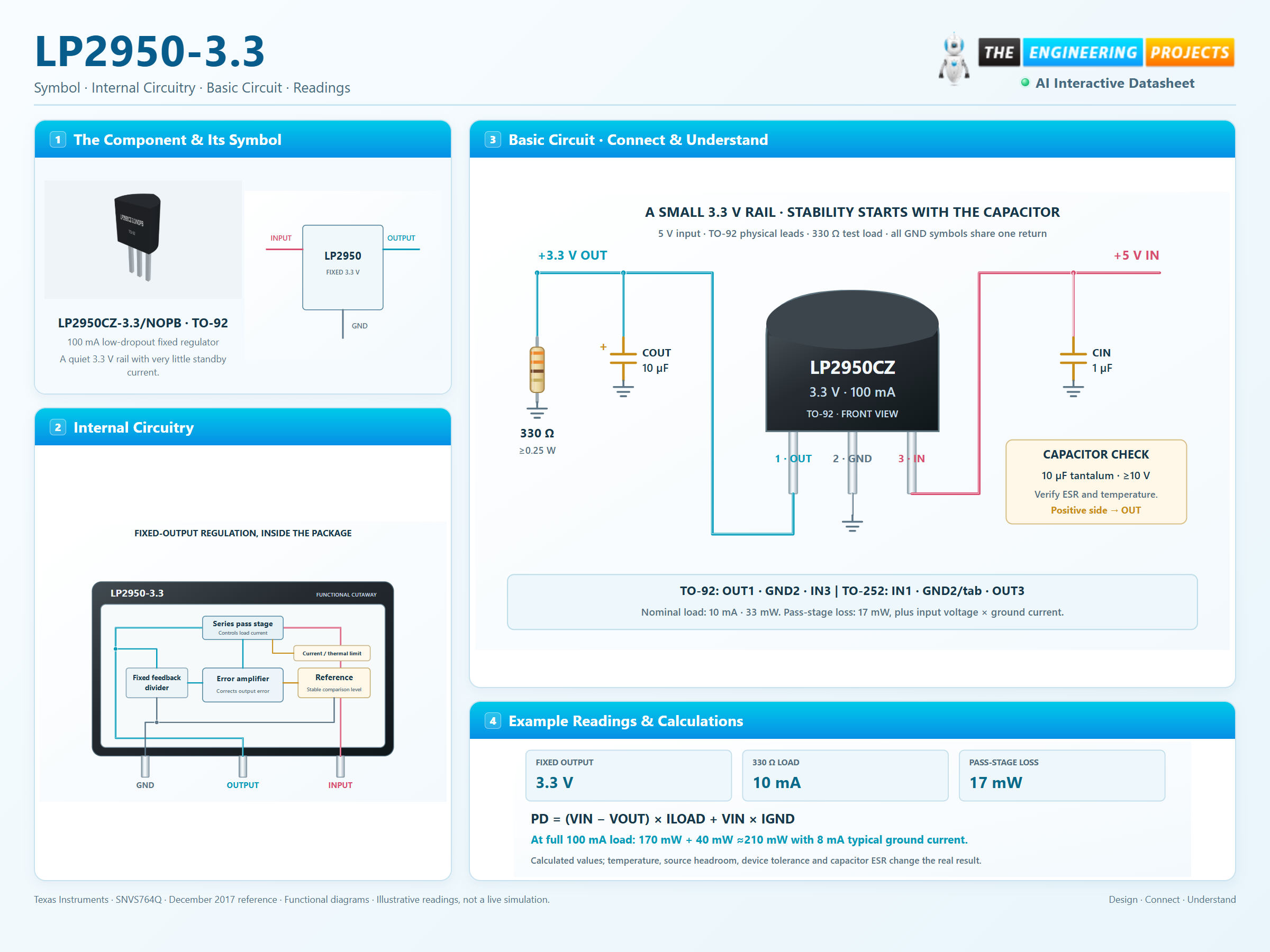
How it works
3 stages · Explore one step at a time
Choose the physical package
TO-92 and TO-252 exchange the IN and OUT pin numbers. The SMD tab belongs to GND.
Stabilize the rail
Place the specified output capacitor close to OUT and GND. Verify effective capacitance and ESR over temperature.
Account for all heat
Use PD=(VIN−VOUT)×ILOAD+VIN×IGND. Ground current rises substantially near full load.
Step 1 of 3
LP2950-3.3 in a circuit
Physical TO-92 leads, golden capacitor symbols and shared ground.
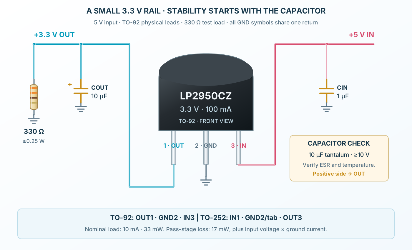
Connect it, step by step
Follow the component values and pin connections
Supply
Apply 5 V to IN3 and common return to GND2.
Stabilize
Fit input bypass and the output capacitor with appropriate ESR.
Load
A 330 Ω load draws nominally 10 mA at 3.3 V.
Inside LP2950-3.3
Reference, feedback and protection inside a compact package.
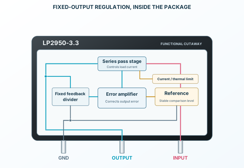
Explore the circuit
Select a stage to see its role and connections
Compare
Compare a fraction of OUT with an internal reference.
Regulate
Control the series-pass stage to hold the 3.3 V rail.
Protect
Current and thermal controls constrain overloads.
Selected packageTO-92LP2950CZ-3.3/NOPB
Physical connections3 pinsPackage-specific numbering
Reference collection8 tables43 parameters & pin functions
Pin reference
Signal names, electrical functions and connection guidance
Physical pin numbers3 pins
Scroll within the table to see all columns and rows.
| Pin | Signal | Type | Function & connection |
|---|---|---|---|
| OUT | Regulated rail | Fixed 3.3 V output; an external stability capacitor is required.Connection guidanceConnect to the load and 10 µF output capacitor; return both to GND. TO-92 pin 1; TO-252 pin 3. Use the selected package map. | |
| GND | Common return | Reference and bias-current return for the regulator.Connection guidanceJoin input return, output capacitor and load grounds locally. Pin 2 in both packages; TO-252 exposed tab is also GND. | |
| IN | Supply input | Supply input for the protected series-pass stage.Connection guidanceUse +5 V in the example and local 1 µF bypass. TO-92 pin 3; TO-252 pin 1. Maximum operating input 30 V; allow design margin. |
No pins match these filters. Try another signal name or reset the filters.
Device and package identity
C-grade fixed 3.3 V parts
Manufacturer-referenced values6 parameters
Scroll within the table to see all columns and rows.
| Parameter | Value | Conditions / notes |
|---|---|---|
| Through-hole order | LP2950CZ-3.3/NOPB | TO-92 LP; straight-lead bulk footprint |
| SMD order | LP2950CDT-3.3/NOPB | TO-252 NDP; formed outer leads and grounded tab |
| TO-92 physical pins | OUT1 · GND2 · IN3 | Flat face toward viewer, leads down |
| TO-252 physical pins | IN1 · GND2 · OUT3 | Front face, leads down; tab is GND |
| Accuracy grade | C: ±1% initial | AC-grade values are not substituted |
| Extra controls | No shutdown or error-output lead | These belong to the related LP2951 |
No specifications match. Try a parameter name or a unit.
Verify order suffix and lead form before fabrication.
Operating ranges and stress limits
Temperature and headroom remain essential
Manufacturer-referenced values6 parameters
Scroll within the table to see all columns and rows.
| Parameter | Value | Conditions / notes |
|---|---|---|
| Nominal output | 3.3 V | Fixed internally; no external divider |
| Recommended input range | 2.3–30 V family range | 3.3 V regulation additionally needs dropout headroom |
| Maximum input stress | 30 V | Do not design at the stress limit |
| Output-current class | 100 mA | Adequate voltage headroom and cooling required |
| Junction operating temperature | −40–125°C | Device junction, not ambient |
| Minimum external load | Not required for LP2950 regulation | Capacitor stability requirements still apply |
No specifications match. Try a parameter name or a unit.
A 2.3 V input cannot produce a regulated 3.3 V output.
C-grade output accuracy
3.3 V option; source conditions retained
Manufacturer-referenced values7 parameters
Scroll within the table to see all columns and rows.
| Parameter | Value | Conditions / notes |
|---|---|---|
| Output at 25°C | 3.267–3.333 V | Nominal 3.3 V |
| Output at −25 to 85°C | 3.251–3.350 V | Manufacturer specified range |
| Output over full temperature | 3.234–3.366 V | −40 to 125°C |
| Across 100 µA–100 mA load | 3.221–3.379 V | Full-temperature limit |
| Temperature coefficient | 50 ppm/°C typical; 150 max. | Output-voltage drift |
| Line regulation at 25°C | 0.04% typical; 0.2% max. | Input from VOUT(nom)+1 V to 30 V |
| Load regulation at 25°C | 0.1% typical; 0.2% max. | Load from 100 µA to 100 mA |
No specifications match. Try a parameter name or a unit.
AC-grade limits are tighter; this page deliberately uses the selected C-grade specification.
Dropout and ground current
Load and temperature change both
Manufacturer-referenced values6 parameters
Scroll within the table to see all columns and rows.
| Parameter | Value | Conditions / notes |
|---|---|---|
| Dropout at 100 µA load, 25°C | 50 mV typical; 80 mV max. | 150 mV maximum over full temperature |
| Dropout at 100 mA load, 25°C | 380 mV typical; 450 mV max. | 600 mV maximum over full temperature |
| Ground current at 100 µA load | 75 µA typical; 120 µA max. at 25°C | 140 µA maximum over full temperature |
| Ground current at 100 mA load | 8 mA typical; 12 mA max. at 25°C | 14 mA maximum over full temperature |
| Short-circuit current | 160 mA typical; 200 mA max. at 25°C | 220 mA maximum over full temperature; not a load rating |
| Full-load example headroom | At least 0.6 V for the full-temperature dropout limit | Allow additional tolerance and ripple margin |
No specifications match. Try a parameter name or a unit.
Dropout is measured when output falls 100 mV below its nominal operating value.
Capacitors and stability
Capacitance alone is not enough
Manufacturer-referenced values6 parameters
Scroll within the table to see all columns and rows.
| Parameter | Value | Conditions / notes |
|---|---|---|
| 3.3 V minimum output capacitor | 2.2 µF | Observe the stability-versus-ESR curves |
| Illustrated output capacitor | 10 µF tantalum, ≥10 V | Choose ESR in the recommended stable region across temperature |
| ESR guidance for 2.2 µF | Approximately 0.05–5 Ω | TI application guidance; larger capacitors have their own curves |
| Ceramic output capacitor | May need 0.1–2 Ω series resistance | Use X5R/X7R and check effective capacitance after DC bias |
| Local input bypass | 1 µF | Particularly for batteries or long supply wiring |
| Example COUT polarity | Positive to OUT; negative to GND | Check voltage rating and startup behavior |
No specifications match. Try a parameter name or a unit.
10 µF helps mitigate some startup/short-recovery overshoot. It is not a guarantee for arbitrary source impedance or capacitor ESR.
Thermal design and losses
Manufacturer thermal-board conditions
Manufacturer-referenced values6 parameters
Scroll within the table to see all columns and rows.
| Parameter | Value | Conditions / notes |
|---|---|---|
| TO-92 θJA | 157.4°C/W | TI reference board; actual assembly varies |
| TO-252 θJA | 51.3°C/W | High-K board with 12 thermal vias |
| TO-252 θJC(bottom) | 2.2°C/W | Grounded exposed tab |
| Total regulator dissipation | (VIN−VOUT)×ILOAD + VIN×IGND | Ground current cannot always be ignored |
| Example 10 mA pass loss | (5−3.3)×0.010 = 17 mW | Add 5×IGND at the actual load |
| Illustrative full-load total | 170 mW + 40 mW = 210 mW | 5 V input, 100 mA load, typical 8 mA ground current |
No specifications match. Try a parameter name or a unit.
Thermal resistance is not an intrinsic promise of available output current.
5 V to 3.3 V working example
A modest test load with clear returns
Manufacturer-referenced values6 parameters
Scroll within the table to see all columns and rows.
| Parameter | Value | Conditions / notes |
|---|---|---|
| Supply / input bypass | 5 V / 1 µF | Common GND return |
| Nominal output | 3.3 V | Actual output follows the C-grade limits |
| Test load | 330 Ω, ≥0.25 W | 3.3/330 = 10 mA |
| Load dissipation | 3.3²/330 = 33 mW | Nominal calculation |
| Output capacitor | 10 µF, ≥10 V, ESR verified | Local placement between OUT and GND |
| Pass-stage loss | 17 mW | Does not include load-dependent ground current |
No specifications match. Try a parameter name or a unit.
Calculated illustration; not measured waveforms or an executable simulation.
No matching rowsTry a pin name, parameter, unit or test condition, or reset the filters.
Small battery rails
Supply low-current electronics with modest dropout and low light-load bias.
Manufacturer application guideAnalog bias supplies
Use the reference accuracy and a stable output network for appropriate analog loads.
Manufacturer application guideStandby electronics
Consider total system leakage and the regulator ground current at the actual load.
Manufacturer application guideTake it into ProTech
Find LP2950-3.3 in the Components Library to place its schematic symbol and connect its pins.
Reference page · circuit simulation model not yet availableOpen ProTech