 BETA
Receive and latch
CLK shifts the command; LOAD selects the destination register.
Explore the internal circuitry and functional stages of MAX7219.
Serial storage, scan control and current drivers inside the IC.
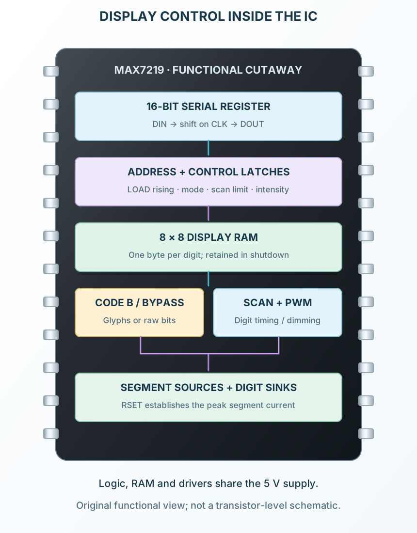
Select a stage to see its role and connections
CLK shifts the command; LOAD selects the destination register.
Each digit has a RAM byte; Code B can be enabled individually.
RSET controls peak segment current; scanning selects digit cathodes.