 BETA
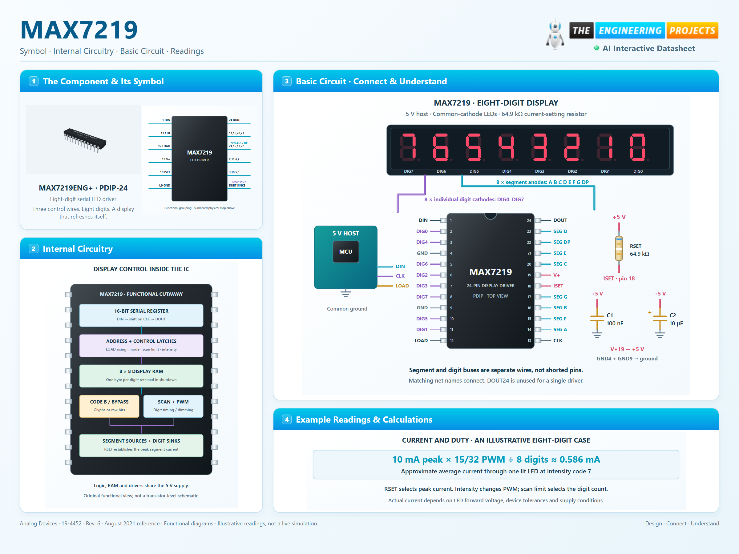
Eight-digit serial LED driver
MAX7219 Working Principle
Learn how MAX7219 works with an illustrated explanation and practical readings.
Package view
MAX7219 at a glance
Follow the labeled connections and functional stages
How it works
3 stages · Explore one step at a time
Wire the display by function
Segment anodes share A–G/DP buses; each digit has its own common cathode.
Load bytes through DIN and CLK
Send address then data, MSB first, and latch with LOAD rising.
Scan and dim in hardware
RAM preserves the pattern while internal scanning and PWM drive the LEDs.
Step 1 of 3