 BETA
Buck / boost / inverting controller
MC34063A Working Principle
Learn how MC34063A works with an illustrated explanation and practical readings.
Package view
MC34063A at a glance
Follow the labeled connections and functional stages
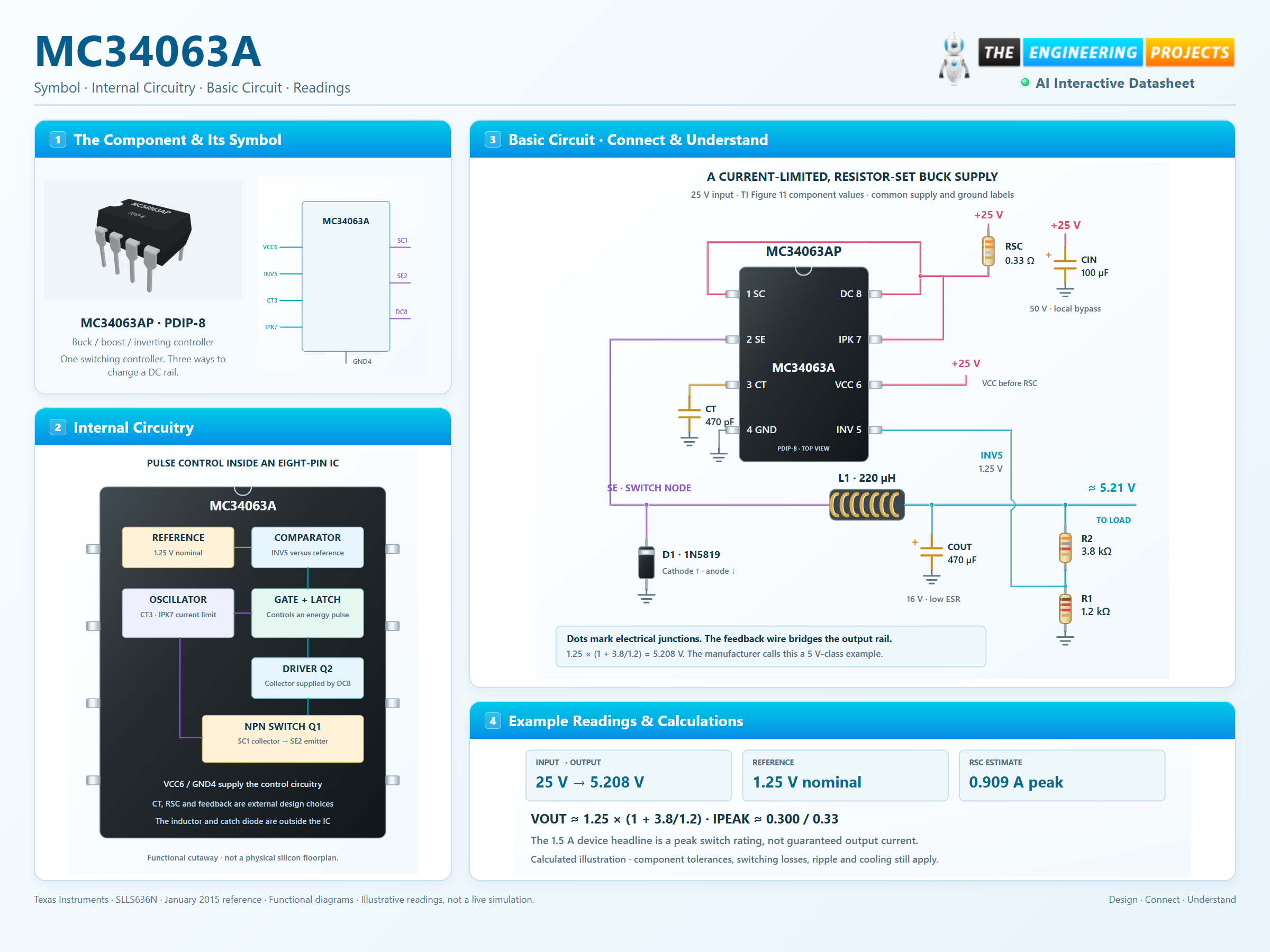
How it works
3 stages · Explore one step at a time
Start an energy pulse
The timing capacitor controls the oscillator. When feedback requests energy, the driver turns the output switch on.
Limit the current
The drop across RSC increases with switch-path current. The sense circuit changes the timing when its threshold is reached.
Hold the output near its setting
Pin 5 compares the divided output against 1.25 V. The inductor and catch diode continue supplying current between switching pulses.
Step 1 of 3