MCP6022Dual rail-to-rail CMOS operational amplifier
Two fast analog channels from a single low-voltage supply.
MCP6022 integrates two CMOS operational amplifiers with rail-to-rail inputs and outputs. Both channels share a 2.5–5.5 V supply, but each has independent signal inputs, feedback and output. The typical gain-bandwidth product is 10 MHz. The example uses a 5 V supply and a common 0.50 V DC input. Channel A has a gain of three and channel B is a voltage follower, producing ideal outputs of 1.50 V and 0.50 V. Local 100 nF bypass and nearby 1 µF bulk storage help keep the supply quiet. This page follows the industrial MCP6022-I/P and MCP6022-I/SN parts, specified from −40 to +85°C. It is the dual amplifier: the reference-voltage output and chip-select feature of certain single-amplifier family members do not exist on MCP6022.

8Physical pins
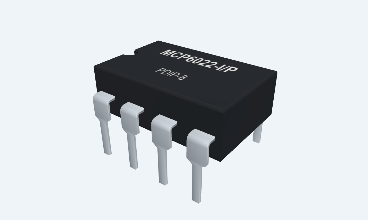
MCP6022-I/PPDIP-8
Manufacturer-referencedMicrochip Technology
Pin diagram
Select a pin to explore its connection
Highlight
MCP6022PDIP-8Top view
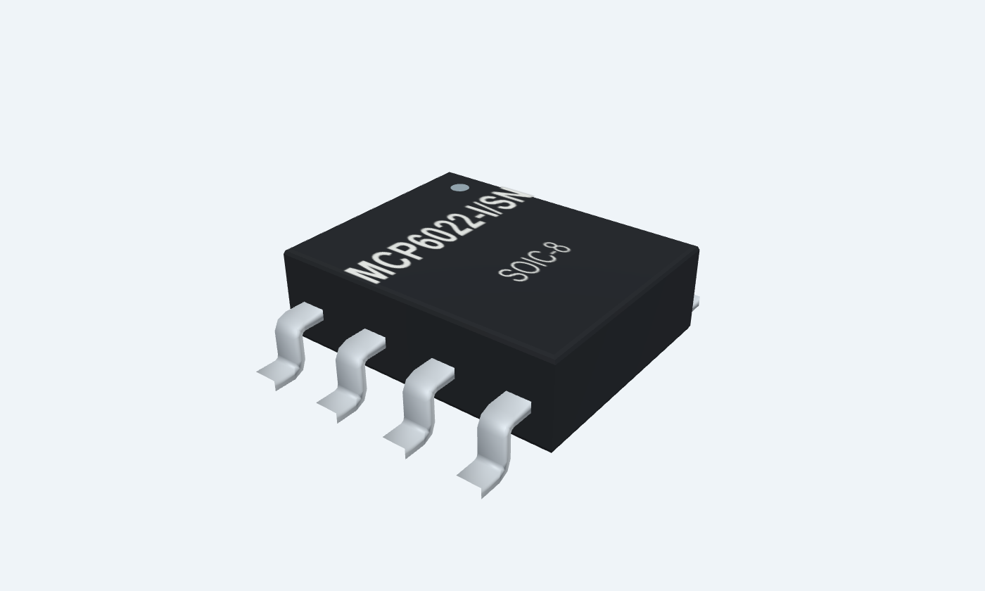
MCP6022SOIC-8Top view
Click a lead or use the arrow keys. Top view
PIN 1 · Analog outputs
Analog outputOUT1
Function
Channel A output.
How to connect
Return to IN1− through 20 kΩ; connect a high-impedance meter.
PIN 2 · Analog inputs
Inverting inputIN1−
Function
Channel A negative-feedback node.
How to connect
Join 20 kΩ from OUT1 and 10 kΩ to signal ground.
PIN 3 · Analog inputs
Non-inverting inputIN1+
Function
Channel A signal input.
How to connect
Apply VIN = 0.50 V relative to ground.
PIN 4 · Ground
Ground returnVSS
Function
Supply return shared by both amplifiers.
How to connect
Connect directly to common ground.
PIN 5 · Analog inputs
Non-inverting inputIN2+
Function
Channel B signal input.
How to connect
Connect to the same VIN in the illustrated follower.
PIN 6 · Analog inputs
Inverting inputIN2−
Function
Channel B feedback input.
How to connect
Connect directly to OUT2 pin 7.
PIN 7 · Analog outputs
Analog outputOUT2
Function
Channel B output.
How to connect
Connect to IN2−; leave unloaded or use a high-impedance instrument.
PIN 8 · Supply
Positive supplyVDD
Function
Positive rail shared by both amplifiers.
How to connect
Connect +5 V; bypass to ground with 100 nF close to pins 8 and 4.
Key specifications
Use independent feedback for each channel, common supply decoupling and clean high-impedance nodes. Allow for source and output loading even in a rail-to-rail circuit.
Supply range2.5–5.5 V
Gain bandwidth10 MHz typical
Voltage noise8.7 nV/√Hz at 10 kHz · typical
Industrial range−40 to +85 °C
Package details
MCP6022-I/P · PDIP-8
| Property | Details |
|---|---|
| Manufacturer | Microchip Technology |
| Part number | MCP6022-I/P |
| Package | PDIP-8 |
| Connections | 8 pins |
| Mounting | Through-hole |
| Lead pitch | 2.54 mm |
| Package code | PDIP-8 |
| Thermal reference | See operating and package limits |
Operating conditions
MCP6022-I/P and MCP6022-I/SN
Manufacturer specifications 7 parameters
Scroll sideways to see all columns.
| Parameter | Value | Conditions / notes |
|---|---|---|
| Supply span | 2.5–5.5 V | VDD minus VSS |
| Industrial ambient range | −40 to +85°C | Selected I-grade parts |
| Input common-mode interval | VSS − 0.3 V to VDD + 0.3 V | Input voltage and current protection limits still apply |
| Example rails | VDD8 = 5 V; VSS4 = 0 V | Supply return is also signal ground |
| Typical current per amplifier | 1.0 mA | 0.5 mA minimum; 1.35 mA maximum, unloaded at 25°C |
| Nominal two-channel current | 2.0 mA | Before external load current |
| No VREF or chip-select pin | MCP6022 has two amplifiers | Do not apply MCP6021/6023 single-amplifier pin functions |
No specifications match. Try a parameter name or a unit.
Unless stated otherwise, electrical values follow the manufacturer 25°C, 2.5–5.5 V, midsupply signal and 10 kΩ-to-midsupply test conditions.
Input accuracy and output swing
Industrial grade · 25°C unless stated
Manufacturer specifications 9 parameters
Scroll sideways to see all columns.
| Parameter | Value | Conditions / notes |
|---|---|---|
| Input offset voltage | ±500 µV maximum | VCM = 0 V; selected industrial grade |
| Typical offset drift | ±3.5 µV/°C | Characterized over −40 to +125°C |
| Input bias current | 1 pA typical | Room temperature |
| Bias current at +85°C | 30 pA typical; 150 pA maximum | Industrial temperature parts |
| Input offset current | ±1 pA typical | Room temperature |
| CMRR over full common-mode range | 74 dB minimum; 90 dB typical | VDD = 5 V; VCM = −0.3 to 5.3 V |
| Supply rejection | 74 dB minimum; 90 dB typical | VCM = 0 V |
| Open-loop gain | 90 dB minimum; 110 dB typical | VCM = 0; VOUT = VSS + 0.3 to VDD − 0.3 V |
| Output swing endpoints | VSS + 15 mV to VDD − 20 mV | 10 kΩ to midsupply; 0.5 V differential overdrive |
No specifications match. Try a parameter name or a unit.
The swing test uses input overdrive; do not treat its endpoints as precision closed-loop headroom at arbitrary load.
Speed and noise
Typical values at manufacturer AC conditions
Manufacturer specifications 8 parameters
Scroll sideways to see all columns.
| Parameter | Value | Conditions / notes |
|---|---|---|
| Gain-bandwidth product | 10 MHz | Closed-loop bandwidth depends on noise gain |
| Slew rate | 7.0 V/µs | Large-signal slope limit |
| Phase margin | 65° | Gain +1; CL = 60 pF |
| Settling to 0.2% | 250 ns | Gain +1; 100 mV peak-to-peak output |
| Voltage-noise density | 8.7 nV/√Hz | 10 kHz |
| Integrated low-frequency noise | 2.9 µV peak-to-peak | 0.1–10 Hz |
| Current-noise density | 3 fA/√Hz | 1 kHz |
| THD + noise | 0.00053% | 1 kHz; gain +1; VDD 5 V; output 0.25–3.25 V; 22 kHz bandwidth |
No specifications match. Try a parameter name or a unit.
Small-signal bandwidth, large-signal slew and settling describe different limitations.
Supply and feedback layout
A fast CMOS amplifier needs short loops
Manufacturer specifications 7 parameters
Scroll sideways to see all columns.
| Parameter | Value | Conditions / notes |
|---|---|---|
| Local bypass | 100 nF in the example | Manufacturer recommends 10–100 nF within 2 mm of VDD |
| Nearby bulk storage | 1 µF or larger | Within 100 mm; may be shared by nearby analog parts |
| Feedback network | Short routes around each input/output pair | The 20 kΩ / 10 kΩ example is a low-frequency demonstration |
| Parasitic capacitance | Check feedback resistance against input and board capacitance | High-frequency noise gain can rise and phase margin can fall |
| Capacitive loads | Choose an isolation network for the actual load | Do not assume stable direct drive of long cables |
| Input leakage | Clean high-impedance nodes | Temperature, moisture and contamination increase errors |
| Unused channel | Stable negative feedback to a valid reference | Do not leave its inputs floating |
No specifications match. Try a parameter name or a unit.
Use the manufacturer capacitive-load and feedback-capacitance guidance for high-frequency designs.
Stress limits and grade distinction
Absolute ratings are not normal operating targets
Manufacturer specifications 6 parameters
Scroll sideways to see all columns.
| Parameter | Value | Conditions / notes |
|---|---|---|
| Absolute supply | 7.0 V | Normal operating upper limit is 5.5 V |
| Analog-input current | ±2 mA absolute maximum | Provide the specified protection if inputs can exceed safe voltage limits |
| Output / supply-pin current | ±30 mA absolute maximum | Not a recommended continuous load current |
| Junction / storage | 150°C maximum / −65 to +150°C | Do not substitute these for ambient operating limits |
| Extended E-grade offset | ±250 µV at 25°C, VDD 5 V, VCM 0 V | A different grade; not used as the I-grade limit here |
| Extended E-grade ambient | −40 to +125°C | The selected I-grade page uses −40 to +85°C |
No specifications match. Try a parameter name or a unit.
Power dissipation and board thermal conditions can constrain usable current before an absolute limit is reached.
Two-channel amplifier example
5 V single supply · common ground
Manufacturer specifications 8 parameters
Scroll sideways to see all columns.
| Parameter | Value | Conditions / notes |
|---|---|---|
| Input VIN | 0.50 V | Pins 3 and 5; common signal ground |
| Channel A feedback | 20 kΩ | OUT1 pin 1 to IN1− pin 2 |
| Channel A ground resistor | 10 kΩ | IN1− pin 2 to 0 V |
| Channel A ideal output | 1.50 V | 0.50 × (1 + 20 / 10) |
| Channel B feedback | Direct connection | OUT2 pin 7 to IN2− pin 6 |
| Channel B ideal output | 0.50 V | Unity-gain follower |
| Bypass capacitors | 100 nF | VDD pin 8 to ground pin 4 |
| Bulk bypass | 1 µF minimum | Nearby between +5 V and GND; may be shared |
No specifications match. Try a parameter name or a unit.
The supply return and signal ground are common. Keep the bypass loop short.
Physical pin reference
MCP6022-I/P · PDIP-8
Manufacturer specifications 5 parameters
Scroll sideways to see all columns.
| Parameter | Value | Conditions / notes |
|---|---|---|
| Lead pitch | 2.54 mm | Through-hole |
| Channel A | OUT1 1; IN1− 2; IN1+ 3 | Independent feedback loop |
| Channel B | IN2+ 5; IN2− 6; OUT2 7 | Independent feedback loop |
| Supply | VSS 4; VDD 8 | Shared by both channels |
| Package orientation | Top view; pin 1 at the marker | Counterclockwise numbering |
No specifications match. Try a parameter name or a unit.
This dual-amplifier pinout differs from single amplifiers such as TL081 or LM741.
Connections by function
Select a pin for its function, connection guidance and electrical notes.
Analog outputs2 pins
Analog inputs4 pins
Ground1 pin
Supply1 pin
Analog outputs2 pins
Analog inputs4 pins
Ground1 pin
Supply1 pin
MCP6022 at a glance
Follow the labeled connections and functional stages
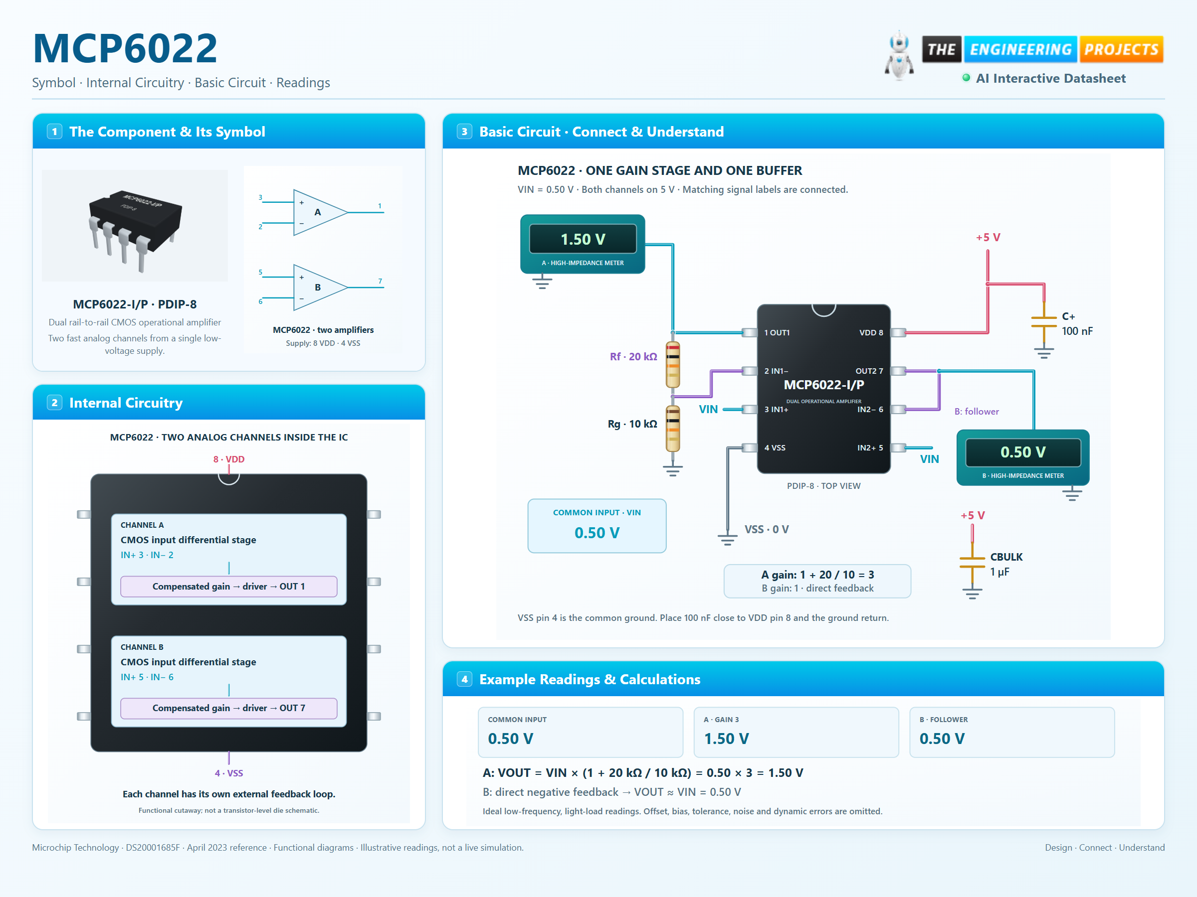
How it works
3 stages · Explore one step at a time
Compare each input pair
Complementary CMOS input paths cover the common-mode range near both supply rails. Their offset and bias behavior still varies with common-mode voltage and temperature; rail-to-rail does not remove input protection limits.
Set two different gains
Channel A uses 20 kΩ feedback and 10 kΩ to the common ground, giving a gain of three. Channel B directly feeds its output back to its negative input, giving unity gain.
Check headroom and speed
With a 0.50 V input, the ideal outputs are 1.50 V and 0.50 V. Real output also depends on input offset, resistor accuracy, loading, noise and signal frequency.
Step 1 of 3
MCP6022 in a circuit
A gain-of-three channel beside a unity-gain follower.
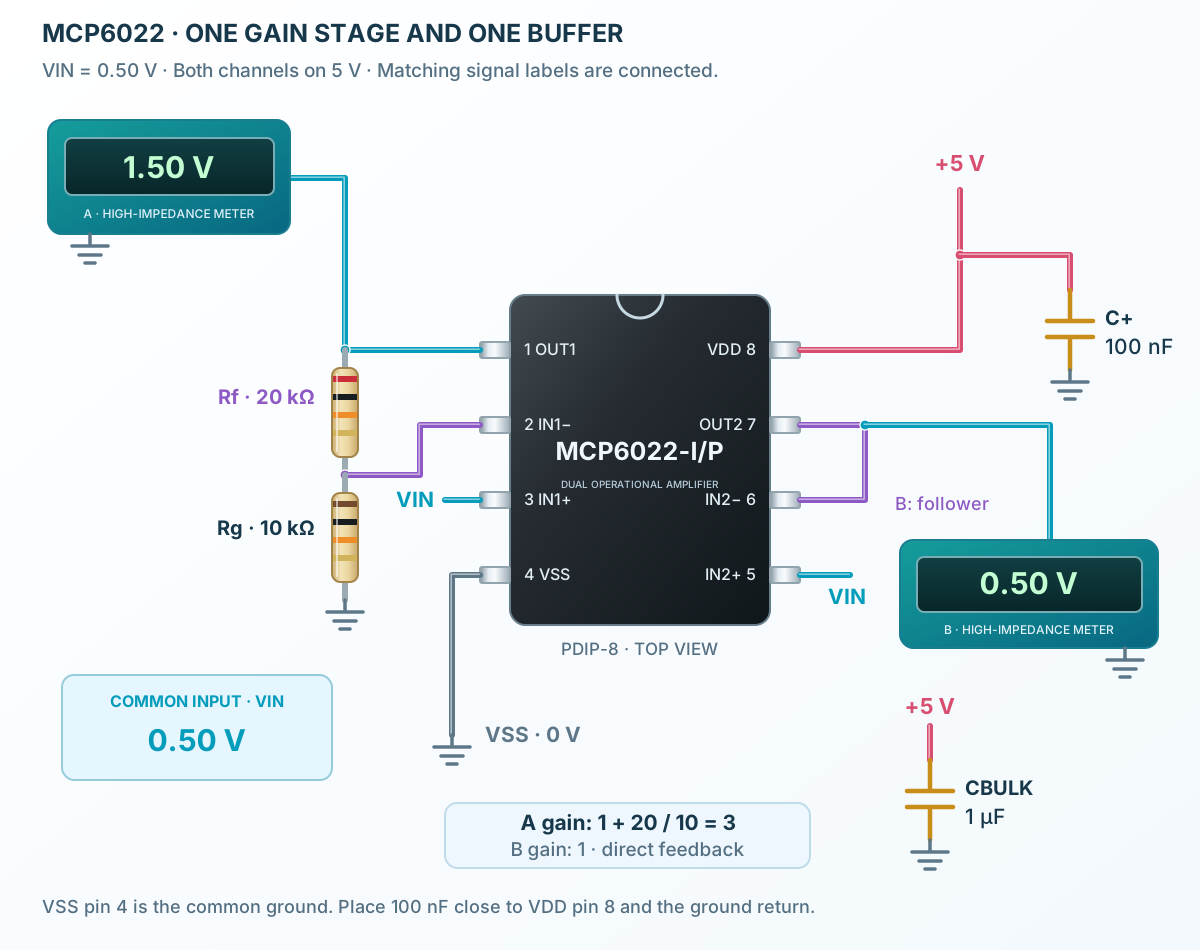
Connect it, step by step
Follow the component values and pin connections
Connect power
Use +5 V at VDD pin 8 and ground at VSS pin 4, with 100 nF between them.
Wire the feedback
Add the 20 kΩ / 10 kΩ network to channel A and join pins 7 and 6 for channel B.
Read both outputs
At a nominal input of 0.50 V, expect about 1.50 V from A and 0.50 V from B under light DC loading.
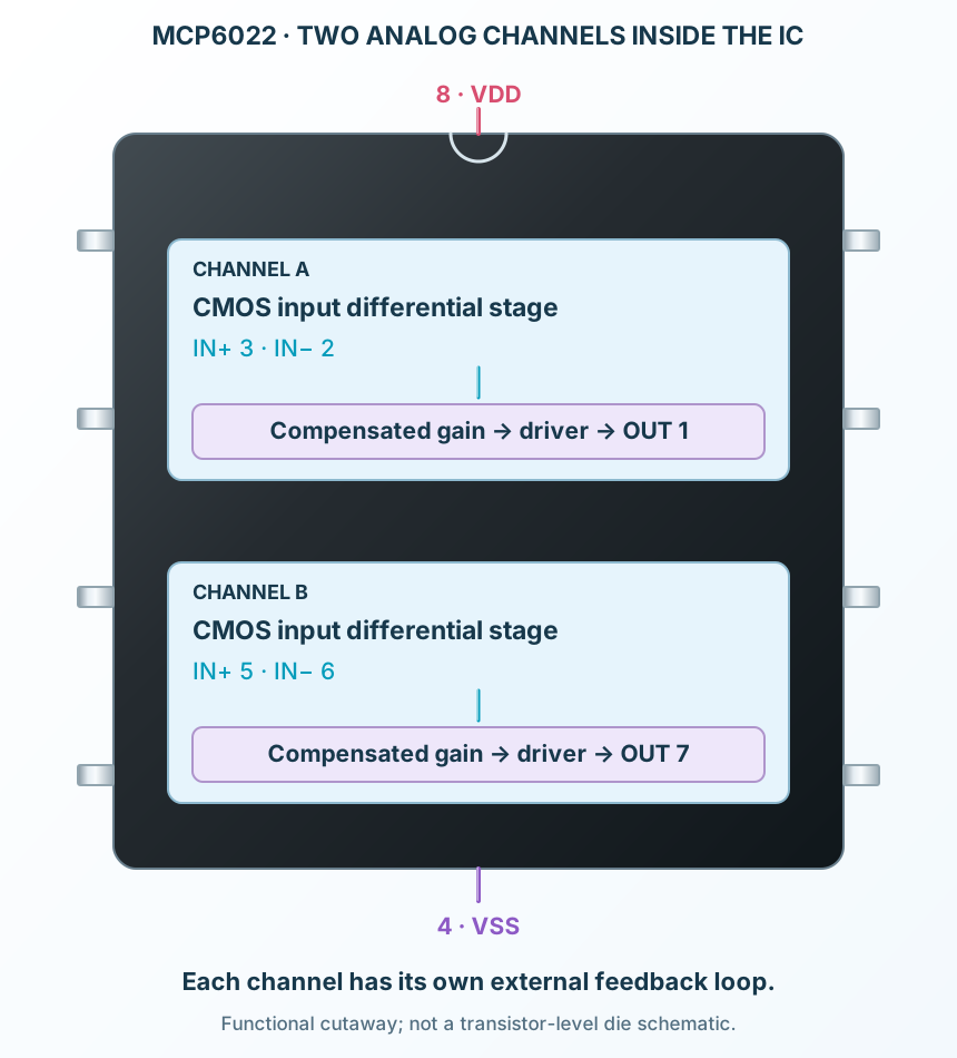
Inside MCP6022
Two CMOS input stages, compensated voltage gain and rail-to-rail output drivers.
Explore the circuit
Select a stage to see its role and connections
Input stages
Complementary CMOS input paths cover the common-mode range near both supply rails. Their offset and bias behavior still varies with common-mode voltage and temperature; rail-to-rail does not remove input protection limits.
Gain and compensation
Each channel has an internal voltage-gain path and frequency compensation.
Output drivers
Each channel drives a compatible load close to its rails. The remaining headroom depends on load and current direction. The short-circuit current is a fault characteristic, not a normal drive-current promise.
Selected packagePDIP-8MCP6022-I/P
Physical connections8 pinsPackage-specific numbering
Reference collection8 tables50 parameters & pin functions
Pin reference
Signal names, electrical functions and connection guidance
Physical pin numbers8 pins
Scroll within the table to see all columns and rows.
| Pin | Signal | Type | Function & connection |
|---|---|---|---|
| OUT1 | Analog output | Channel A output.Connection guidanceReturn to IN1− through 20 kΩ; connect a high-impedance meter. | |
| IN1− | Inverting input | Channel A negative-feedback node.Connection guidanceJoin 20 kΩ from OUT1 and 10 kΩ to signal ground. | |
| IN1+ | Non-inverting input | Channel A signal input.Connection guidanceApply VIN = 0.50 V relative to ground. | |
| VSS | Ground return | Supply return shared by both amplifiers.Connection guidanceConnect directly to common ground. | |
| IN2+ | Non-inverting input | Channel B signal input.Connection guidanceConnect to the same VIN in the illustrated follower. | |
| IN2− | Inverting input | Channel B feedback input.Connection guidanceConnect directly to OUT2 pin 7. | |
| OUT2 | Analog output | Channel B output.Connection guidanceConnect to IN2−; leave unloaded or use a high-impedance instrument. | |
| VDD | Positive supply | Positive rail shared by both amplifiers.Connection guidanceConnect +5 V; bypass to ground with 100 nF close to pins 8 and 4. |
No pins match these filters. Try another signal name or reset the filters.
Operating conditions
MCP6022-I/P and MCP6022-I/SN
Manufacturer-referenced values7 parameters
Scroll within the table to see all columns and rows.
| Parameter | Value | Conditions / notes |
|---|---|---|
| Supply span | 2.5–5.5 V | VDD minus VSS |
| Industrial ambient range | −40 to +85°C | Selected I-grade parts |
| Input common-mode interval | VSS − 0.3 V to VDD + 0.3 V | Input voltage and current protection limits still apply |
| Example rails | VDD8 = 5 V; VSS4 = 0 V | Supply return is also signal ground |
| Typical current per amplifier | 1.0 mA | 0.5 mA minimum; 1.35 mA maximum, unloaded at 25°C |
| Nominal two-channel current | 2.0 mA | Before external load current |
| No VREF or chip-select pin | MCP6022 has two amplifiers | Do not apply MCP6021/6023 single-amplifier pin functions |
No specifications match. Try a parameter name or a unit.
Unless stated otherwise, electrical values follow the manufacturer 25°C, 2.5–5.5 V, midsupply signal and 10 kΩ-to-midsupply test conditions.
Input accuracy and output swing
Industrial grade · 25°C unless stated
Manufacturer-referenced values9 parameters
Scroll within the table to see all columns and rows.
| Parameter | Value | Conditions / notes |
|---|---|---|
| Input offset voltage | ±500 µV maximum | VCM = 0 V; selected industrial grade |
| Typical offset drift | ±3.5 µV/°C | Characterized over −40 to +125°C |
| Input bias current | 1 pA typical | Room temperature |
| Bias current at +85°C | 30 pA typical; 150 pA maximum | Industrial temperature parts |
| Input offset current | ±1 pA typical | Room temperature |
| CMRR over full common-mode range | 74 dB minimum; 90 dB typical | VDD = 5 V; VCM = −0.3 to 5.3 V |
| Supply rejection | 74 dB minimum; 90 dB typical | VCM = 0 V |
| Open-loop gain | 90 dB minimum; 110 dB typical | VCM = 0; VOUT = VSS + 0.3 to VDD − 0.3 V |
| Output swing endpoints | VSS + 15 mV to VDD − 20 mV | 10 kΩ to midsupply; 0.5 V differential overdrive |
No specifications match. Try a parameter name or a unit.
The swing test uses input overdrive; do not treat its endpoints as precision closed-loop headroom at arbitrary load.
Speed and noise
Typical values at manufacturer AC conditions
Manufacturer-referenced values8 parameters
Scroll within the table to see all columns and rows.
| Parameter | Value | Conditions / notes |
|---|---|---|
| Gain-bandwidth product | 10 MHz | Closed-loop bandwidth depends on noise gain |
| Slew rate | 7.0 V/µs | Large-signal slope limit |
| Phase margin | 65° | Gain +1; CL = 60 pF |
| Settling to 0.2% | 250 ns | Gain +1; 100 mV peak-to-peak output |
| Voltage-noise density | 8.7 nV/√Hz | 10 kHz |
| Integrated low-frequency noise | 2.9 µV peak-to-peak | 0.1–10 Hz |
| Current-noise density | 3 fA/√Hz | 1 kHz |
| THD + noise | 0.00053% | 1 kHz; gain +1; VDD 5 V; output 0.25–3.25 V; 22 kHz bandwidth |
No specifications match. Try a parameter name or a unit.
Small-signal bandwidth, large-signal slew and settling describe different limitations.
Supply and feedback layout
A fast CMOS amplifier needs short loops
Manufacturer-referenced values7 parameters
Scroll within the table to see all columns and rows.
| Parameter | Value | Conditions / notes |
|---|---|---|
| Local bypass | 100 nF in the example | Manufacturer recommends 10–100 nF within 2 mm of VDD |
| Nearby bulk storage | 1 µF or larger | Within 100 mm; may be shared by nearby analog parts |
| Feedback network | Short routes around each input/output pair | The 20 kΩ / 10 kΩ example is a low-frequency demonstration |
| Parasitic capacitance | Check feedback resistance against input and board capacitance | High-frequency noise gain can rise and phase margin can fall |
| Capacitive loads | Choose an isolation network for the actual load | Do not assume stable direct drive of long cables |
| Input leakage | Clean high-impedance nodes | Temperature, moisture and contamination increase errors |
| Unused channel | Stable negative feedback to a valid reference | Do not leave its inputs floating |
No specifications match. Try a parameter name or a unit.
Use the manufacturer capacitive-load and feedback-capacitance guidance for high-frequency designs.
Stress limits and grade distinction
Absolute ratings are not normal operating targets
Manufacturer-referenced values6 parameters
Scroll within the table to see all columns and rows.
| Parameter | Value | Conditions / notes |
|---|---|---|
| Absolute supply | 7.0 V | Normal operating upper limit is 5.5 V |
| Analog-input current | ±2 mA absolute maximum | Provide the specified protection if inputs can exceed safe voltage limits |
| Output / supply-pin current | ±30 mA absolute maximum | Not a recommended continuous load current |
| Junction / storage | 150°C maximum / −65 to +150°C | Do not substitute these for ambient operating limits |
| Extended E-grade offset | ±250 µV at 25°C, VDD 5 V, VCM 0 V | A different grade; not used as the I-grade limit here |
| Extended E-grade ambient | −40 to +125°C | The selected I-grade page uses −40 to +85°C |
No specifications match. Try a parameter name or a unit.
Power dissipation and board thermal conditions can constrain usable current before an absolute limit is reached.
Two-channel amplifier example
5 V single supply · common ground
Manufacturer-referenced values8 parameters
Scroll within the table to see all columns and rows.
| Parameter | Value | Conditions / notes |
|---|---|---|
| Input VIN | 0.50 V | Pins 3 and 5; common signal ground |
| Channel A feedback | 20 kΩ | OUT1 pin 1 to IN1− pin 2 |
| Channel A ground resistor | 10 kΩ | IN1− pin 2 to 0 V |
| Channel A ideal output | 1.50 V | 0.50 × (1 + 20 / 10) |
| Channel B feedback | Direct connection | OUT2 pin 7 to IN2− pin 6 |
| Channel B ideal output | 0.50 V | Unity-gain follower |
| Bypass capacitors | 100 nF | VDD pin 8 to ground pin 4 |
| Bulk bypass | 1 µF minimum | Nearby between +5 V and GND; may be shared |
No specifications match. Try a parameter name or a unit.
The supply return and signal ground are common. Keep the bypass loop short.
Physical pin reference
MCP6022-I/P · PDIP-8
Manufacturer-referenced values5 parameters
Scroll within the table to see all columns and rows.
| Parameter | Value | Conditions / notes |
|---|---|---|
| Lead pitch | 2.54 mm | Through-hole |
| Channel A | OUT1 1; IN1− 2; IN1+ 3 | Independent feedback loop |
| Channel B | IN2+ 5; IN2− 6; OUT2 7 | Independent feedback loop |
| Supply | VSS 4; VDD 8 | Shared by both channels |
| Package orientation | Top view; pin 1 at the marker | Counterclockwise numbering |
No specifications match. Try a parameter name or a unit.
This dual-amplifier pinout differs from single amplifiers such as TL081 or LM741.
No matching rowsTry a pin name, parameter, unit or test condition, or reset the filters.
Sensor gain and buffering
Amplify compatible low-voltage sensor signals while checking bandwidth and ADC settling.
Manufacturer application guideActive filtering
Build two-channel or cascaded filters with adequate noise-gain and phase-margin allowance.
Manufacturer application guideAudio and test equipment
Use the low-noise dual amplifier with suitable bias, loading and supply bypass.
Manufacturer application guideTake it into ProTech
Find MCP6022 in the Components Library to place its schematic symbol and connect its pins.
Reference page · circuit simulation model not yet availableOpen ProTech