Real View
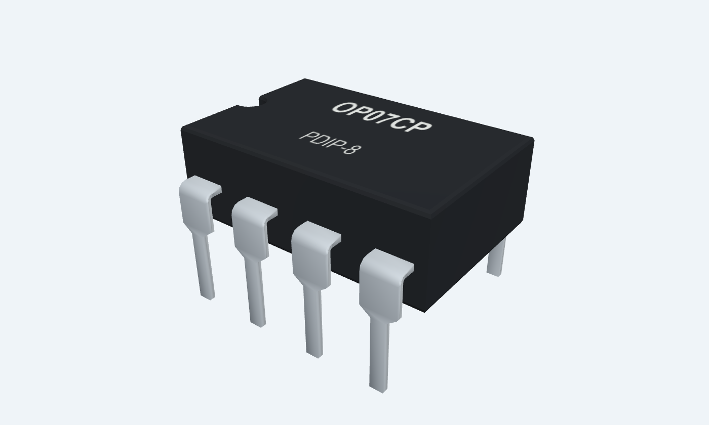
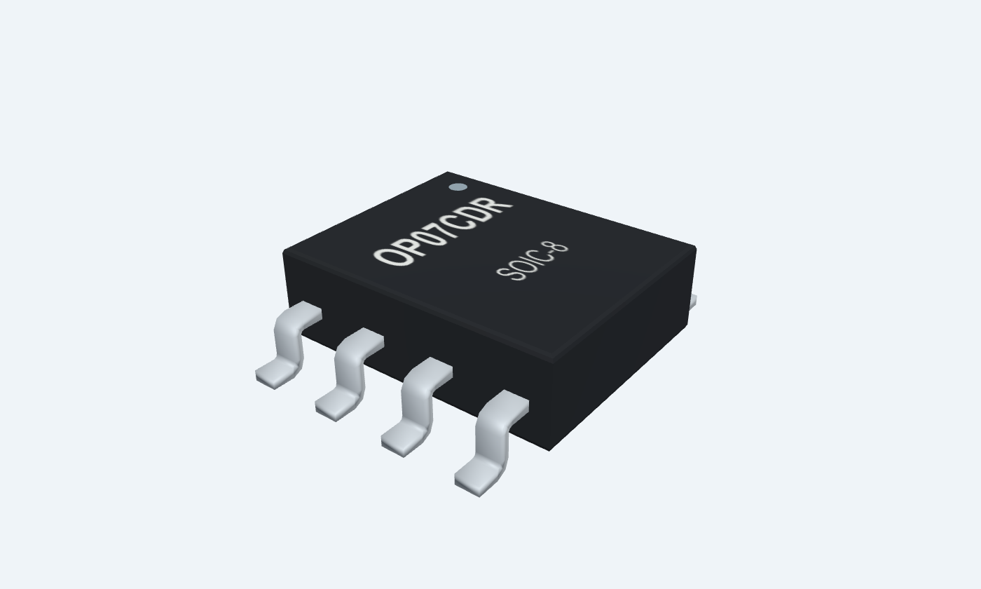
Small input errors matter. Build a clearer precision signal path.
OP07 is a precision operational-amplifier family using a low-noise bipolar input stage and internal compensation. Negative feedback produces a controlled analog gain while low offset and drift help preserve small DC signals. It is a precision amplifier rather than a rail-to-rail or high-speed device. This page selects TI OP07CP in PDIP-8 and OP07CDR in SOIC-8, both commercial C-grade parts. Offset trim uses pins 1 and 8; pin 5 is unconnected. Package views and footprints preserve this mapping, which differs from the familiar LM741 trim arrangement. The example uses ±15 V rails, 90 kΩ feedback and 10 kΩ to the 0 V midpoint. A 0.20 V input gives an ideal 2.00 V output. The reference tables distinguish typical values from guaranteed limits; precision also depends on resistor accuracy, leakage, thermal gradients and the measurement setup.
Select a pin to explore its connection
Click a lead or use the arrow keys. Top view
First terminal of the optional input-offset trim network.
Leave open in the illustrated circuit.
Use TI’s trim network only when needed; its other end is pin 8.
Negative-feedback summing node.
Connect the 90 kΩ/10 kΩ resistor junction.
Positive signal input.
Apply 0.20 V relative to the 0 V supply midpoint.
Negative power rail.
Connect −15 V; bypass locally to 0 V with 100 nF.
Not signal ground in this circuit.
No electrical connection is specified for this pin.
Leave unconnected.
Amplifier output and feedback source.
Connect 90 kΩ to IN− 2 and a high-impedance output meter.
Positive power rail.
Connect +15 V; bypass locally to 0 V with 100 nF.
Second terminal of the optional input-offset trim network.
Leave open in the illustrated circuit.
Paired with pin 1; this is not the LM741 null-pin arrangement.
Input offset is only one error term. Include bias-current drops, resistor ratios, thermal gradients and loading before treating a result as accurate.
OP07CP · PDIP-8
| Property | Details |
|---|---|
| Manufacturer | Texas Instruments |
| Part number | OP07CP |
| Package | PDIP-8 |
| Connections | 8 pins |
| Mounting | Through-hole |
| Lead pitch | 2.54 mm |
| Package code | dip |
| Thermal reference | θJA85°C/W on TI reference board |
TI OP07C reference
Scroll sideways to see all columns.
| Parameter | Value | Conditions / notes |
|---|---|---|
| Recommended split supply | ±3 to±18 V | 6–36 V total span |
| Example rails | ±15 V | 0 V midpoint is signal ground |
| Ambient range | 0–70°C | Selected commercial C grade |
| Common-mode recommended at±15 V | −13 to+13 V | Do not infer rail-to-rail operation |
| Absolute supply maximum | ±22 V | Stress limit, not an operating target |
| Input absolute limit note | Magnitude no greater than supply or15 V, whichever is less | Manufacturer footnote applies |
| Local bypass | 100 nF per rail to 0 V | Short return paths near pins 7 and 4 |
No specifications match. Try a parameter name or a unit.
Do not substitute the absolute stress values for recommended operation.
±15 V,25°C unless stated; column labels retained
Scroll sideways to see all columns.
| Parameter | Value | Conditions / notes |
|---|---|---|
| Input offset voltage | ±60 µV typical | ±85 µV typical across0–70°C |
| Offset drift | ±0.5 µV/°C typical | C grade; not a guaranteed maximum |
| Long-term offset drift | ±0.4 µV/month typical estimate | Average trend after first30 days; not individually guaranteed |
| Input bias current | ±1.8 nA typical | ±2.2 nA typical across0–70°C |
| Input offset current | ±0.8 nA typical | ±1.6 nA typical across0–70°C |
| Bias-current drift | ±18 pA/°C typical | C-grade table |
| Offset adjustment range | ±4 mV typical | Rs20 kΩ; optional manufacturer trim network |
No specifications match. Try a parameter name or a unit.
TI revision H places these C-grade values in the typical column. They are not maximum-error guarantees.
Use the bandwidth and source conditions
Scroll sideways to see all columns.
| Parameter | Value | Conditions / notes |
|---|---|---|
| Voltage noise,0.1–10 Hz | 0.38 µV peak-to-peak typical | Not RMS |
| Voltage noise density at10 Hz | 10.5 nV/√Hz typical | Input-referred |
| Voltage noise density at1 kHz | 9.8 nV/√Hz typical | Input-referred |
| Current noise density at1 kHz | 0.13 pA/√Hz typical | Source resistance converts it to voltage noise |
| C-grade CMRR at25°C | 100 dB minimum;120 dB typical | VCM±13 V |
| C-grade CMRR over0–70°C | 97 dB minimum;120 dB typical | VCM±13 V |
| Supply sensitivity at25°C | 7 µV/V typical;32 µV/V maximum | VS±3 to±18 V |
| Supply sensitivity over0–70°C | 10 µV/V typical;51 µV/V maximum | Lower is better; table usesµV/V |
No specifications match. Try a parameter name or a unit.
Noise densities must be integrated over the circuit bandwidth.
Manufacturer test conditions
Scroll sideways to see all columns.
| Parameter | Value | Conditions / notes |
|---|---|---|
| Unity-gain bandwidth | 0.4 MHz minimum;0.6 MHz typical | Standard table conditions |
| Slew rate | 0.3 V/µs typical | VS5 V;RL2 kΩ per source table |
| Output swing at25°C,RL2 kΩ | ±11.5 V minimum;±12.8 V typical | VS±15 V |
| Output swing over0–70°C,RL2 kΩ | ±11 V minimum;±12.6 V typical | VS±15 V |
| Output swing atRL10 kΩ | ±12 V minimum;±13 V typical | VS±15 V |
| No-load device power at±15 V | 80 mW typical;150 mW maximum | Not output power |
| No-load device power at±3 V | 4 mW typical;8 mW maximum | Lower-supply condition |
No specifications match. Try a parameter name or a unit.
Check headroom and settling; this is not a high-speed amplifier.
Calculated DC illustration
Scroll sideways to see all columns.
| Parameter | Value | Conditions / notes |
|---|---|---|
| VIN | 0.20 V | Non-inverting pin 3 |
| Feedback resistor | 90 kΩ | OUT 6 to IN− 2 |
| Ground resistor | 10 kΩ | IN− 2 to 0 V midpoint |
| Ideal gain | 10 V/V | 1+90/10 |
| Ideal output | 2.00 V | 0.20×10 |
| Typical offset contribution | About0.60 mV at output | 60 µV×noise gain 10; not total error |
| Unused trim / NC | 1 and 8 open; 5 unconnected | Optional offset adjustment omitted |
No specifications match. Try a parameter name or a unit.
Select resistor ratio tolerance for the required accuracy; the illustration is not calibrated hardware.
OP07CP ·PDIP-8
Scroll sideways to see all columns.
| Parameter | Value | Conditions / notes |
|---|---|---|
| Lead pitch | 2.54 mm | Through-hole |
| Input pair | 2 IN−;3 IN+ | Keep leakage and contamination low |
| Supply | 4 V−;7 V+ | Both locally bypassed |
| Output | 6 | Return feedback close to the input network |
| Optional trim | 1 NULL1;8 NULL2 | Follow the exact manufacturer circuit |
| No connection | 5 | Leave open |
| Thermal layout | Avoid uneven heating near input nodes | Thermoelectric voltages can matter at µV levels |
No specifications match. Try a parameter name or a unit.
Top view, counterclockwise numbering; pin 1 at the marker.
Select a pin for its function, connection guidance and electrical notes.
Follow the labeled connections and functional stages
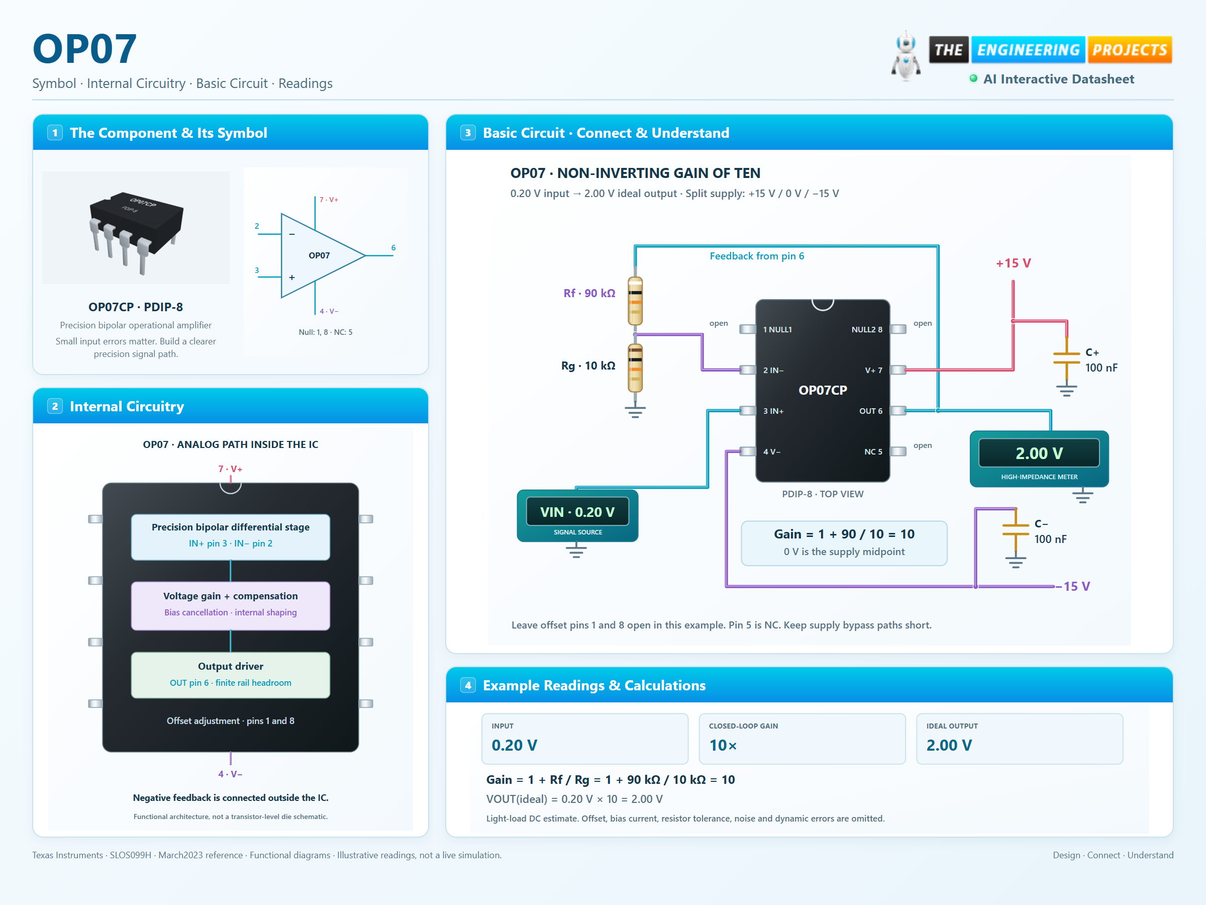
3 stages · Explore one step at a time
The bipolar input stage responds to the difference between pins 3 and 2.
90 kΩ from OUT 6 to IN− 2 and 10 kΩ from IN− 2 to 0 V give a noise gain of ten.
Check offset, input currents, resistor tolerance, temperature and settling before reading a small signal.
A physical eight-pin IC, feedback resistors and local bypass.
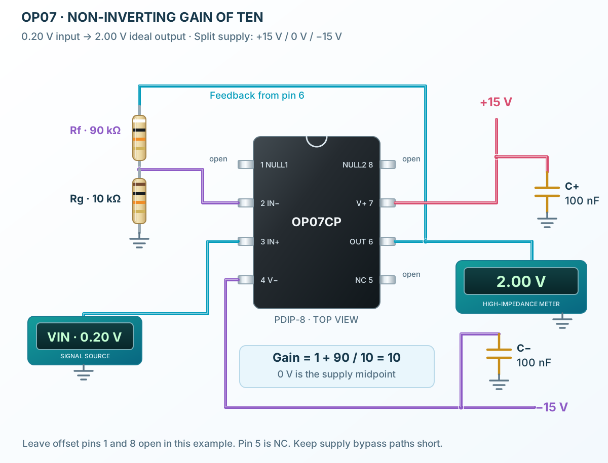
Follow the component values and pin connections
Apply ±15 V to7 and 4; bypass both rails to 0 V.
Use 90 kΩ/10 kΩ for gain ten.
Read near 2.00 V with a high-impedance meter; include device and resistor errors.
Precision bipolar inputs and compensated gain within the IC.
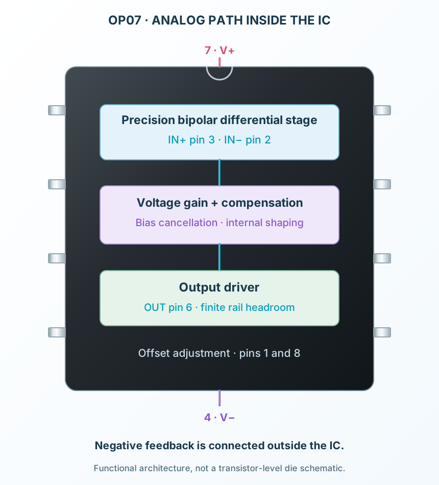
Select a stage to see its role and connections
The input stage senses a small differential voltage with bias-current cancellation.
Internally compensated gain supports ordinary closed-loop operation.
The output stage drives the feedback network and compatible load.
Signal names, electrical functions and connection guidance
Scroll within the table to see all columns and rows.
| Pin | Signal | Type | Function & connection |
|---|---|---|---|
| NULL1 | Optional offset adjustment | First terminal of the optional input-offset trim network.Connection guidanceLeave open in the illustrated circuit. Use TI’s trim network only when needed; its other end is pin 8. | |
| IN− | Inverting input | Negative-feedback summing node.Connection guidanceConnect the 90 kΩ/10 kΩ resistor junction. | |
| IN+ | Non-inverting input | Positive signal input.Connection guidanceApply 0.20 V relative to the 0 V supply midpoint. | |
| V− | Negative supply | Negative power rail.Connection guidanceConnect −15 V; bypass locally to 0 V with 100 nF. Not signal ground in this circuit. | |
| NC | No connection | No electrical connection is specified for this pin.Connection guidanceLeave unconnected. | |
| OUT | Analog output | Amplifier output and feedback source.Connection guidanceConnect 90 kΩ to IN− 2 and a high-impedance output meter. | |
| V+ | Positive supply | Positive power rail.Connection guidanceConnect +15 V; bypass locally to 0 V with 100 nF. | |
| NULL2 | Optional offset adjustment | Second terminal of the optional input-offset trim network.Connection guidanceLeave open in the illustrated circuit. Paired with pin 1; this is not the LM741 null-pin arrangement. |
No pins match these filters. Try another signal name or reset the filters.
TI OP07C reference
Scroll within the table to see all columns and rows.
| Parameter | Value | Conditions / notes |
|---|---|---|
| Recommended split supply | ±3 to±18 V | 6–36 V total span |
| Example rails | ±15 V | 0 V midpoint is signal ground |
| Ambient range | 0–70°C | Selected commercial C grade |
| Common-mode recommended at±15 V | −13 to+13 V | Do not infer rail-to-rail operation |
| Absolute supply maximum | ±22 V | Stress limit, not an operating target |
| Input absolute limit note | Magnitude no greater than supply or15 V, whichever is less | Manufacturer footnote applies |
| Local bypass | 100 nF per rail to 0 V | Short return paths near pins 7 and 4 |
No specifications match. Try a parameter name or a unit.
Do not substitute the absolute stress values for recommended operation.
±15 V,25°C unless stated; column labels retained
Scroll within the table to see all columns and rows.
| Parameter | Value | Conditions / notes |
|---|---|---|
| Input offset voltage | ±60 µV typical | ±85 µV typical across0–70°C |
| Offset drift | ±0.5 µV/°C typical | C grade; not a guaranteed maximum |
| Long-term offset drift | ±0.4 µV/month typical estimate | Average trend after first30 days; not individually guaranteed |
| Input bias current | ±1.8 nA typical | ±2.2 nA typical across0–70°C |
| Input offset current | ±0.8 nA typical | ±1.6 nA typical across0–70°C |
| Bias-current drift | ±18 pA/°C typical | C-grade table |
| Offset adjustment range | ±4 mV typical | Rs20 kΩ; optional manufacturer trim network |
No specifications match. Try a parameter name or a unit.
TI revision H places these C-grade values in the typical column. They are not maximum-error guarantees.
Use the bandwidth and source conditions
Scroll within the table to see all columns and rows.
| Parameter | Value | Conditions / notes |
|---|---|---|
| Voltage noise,0.1–10 Hz | 0.38 µV peak-to-peak typical | Not RMS |
| Voltage noise density at10 Hz | 10.5 nV/√Hz typical | Input-referred |
| Voltage noise density at1 kHz | 9.8 nV/√Hz typical | Input-referred |
| Current noise density at1 kHz | 0.13 pA/√Hz typical | Source resistance converts it to voltage noise |
| C-grade CMRR at25°C | 100 dB minimum;120 dB typical | VCM±13 V |
| C-grade CMRR over0–70°C | 97 dB minimum;120 dB typical | VCM±13 V |
| Supply sensitivity at25°C | 7 µV/V typical;32 µV/V maximum | VS±3 to±18 V |
| Supply sensitivity over0–70°C | 10 µV/V typical;51 µV/V maximum | Lower is better; table usesµV/V |
No specifications match. Try a parameter name or a unit.
Noise densities must be integrated over the circuit bandwidth.
Manufacturer test conditions
Scroll within the table to see all columns and rows.
| Parameter | Value | Conditions / notes |
|---|---|---|
| Unity-gain bandwidth | 0.4 MHz minimum;0.6 MHz typical | Standard table conditions |
| Slew rate | 0.3 V/µs typical | VS5 V;RL2 kΩ per source table |
| Output swing at25°C,RL2 kΩ | ±11.5 V minimum;±12.8 V typical | VS±15 V |
| Output swing over0–70°C,RL2 kΩ | ±11 V minimum;±12.6 V typical | VS±15 V |
| Output swing atRL10 kΩ | ±12 V minimum;±13 V typical | VS±15 V |
| No-load device power at±15 V | 80 mW typical;150 mW maximum | Not output power |
| No-load device power at±3 V | 4 mW typical;8 mW maximum | Lower-supply condition |
No specifications match. Try a parameter name or a unit.
Check headroom and settling; this is not a high-speed amplifier.
Calculated DC illustration
Scroll within the table to see all columns and rows.
| Parameter | Value | Conditions / notes |
|---|---|---|
| VIN | 0.20 V | Non-inverting pin 3 |
| Feedback resistor | 90 kΩ | OUT 6 to IN− 2 |
| Ground resistor | 10 kΩ | IN− 2 to 0 V midpoint |
| Ideal gain | 10 V/V | 1+90/10 |
| Ideal output | 2.00 V | 0.20×10 |
| Typical offset contribution | About0.60 mV at output | 60 µV×noise gain 10; not total error |
| Unused trim / NC | 1 and 8 open; 5 unconnected | Optional offset adjustment omitted |
No specifications match. Try a parameter name or a unit.
Select resistor ratio tolerance for the required accuracy; the illustration is not calibrated hardware.
OP07CP ·PDIP-8
Scroll within the table to see all columns and rows.
| Parameter | Value | Conditions / notes |
|---|---|---|
| Lead pitch | 2.54 mm | Through-hole |
| Input pair | 2 IN−;3 IN+ | Keep leakage and contamination low |
| Supply | 4 V−;7 V+ | Both locally bypassed |
| Output | 6 | Return feedback close to the input network |
| Optional trim | 1 NULL1;8 NULL2 | Follow the exact manufacturer circuit |
| No connection | 5 | Leave open |
| Thermal layout | Avoid uneven heating near input nodes | Thermoelectric voltages can matter at µV levels |
No specifications match. Try a parameter name or a unit.
Top view, counterclockwise numbering; pin 1 at the marker.
No matching rowsTry a pin name, parameter, unit or test condition, or reset the filters.
Condition small, slow signals with a complete offset and resistor error budget.
Manufacturer application guideBuffer compatible voltage references while accounting for loading and input current.
Manufacturer application guideAmplify low-frequency sensor outputs while controlling leakage and thermal gradients.
Manufacturer application guideFind OP07 in the Components Library to place its schematic symbol and connect its pins.
Reference page · circuit simulation model not yet availableOpen ProTech