 BETA
First PNP stage
Base current controls the first transistor.
Explore the internal circuitry and functional stages of TIP127.
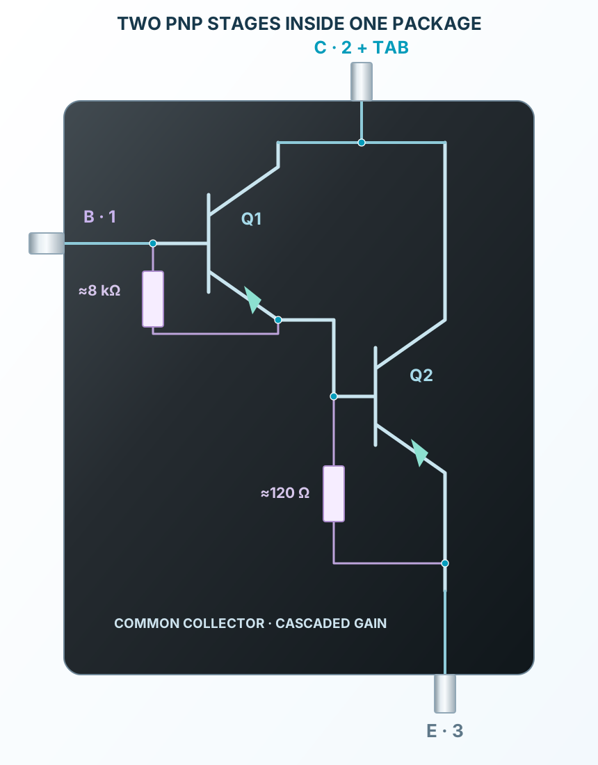
Two PNP stages, common collector and internal discharge resistors.
Select a stage to see its role and connections
Base current controls the first transistor.
The first emitter feeds the second base; both collectors are joined.
TIP127’s reference shows approximately 8 kΩ and 120 Ω shunts; this is a functional schematic.