Real View
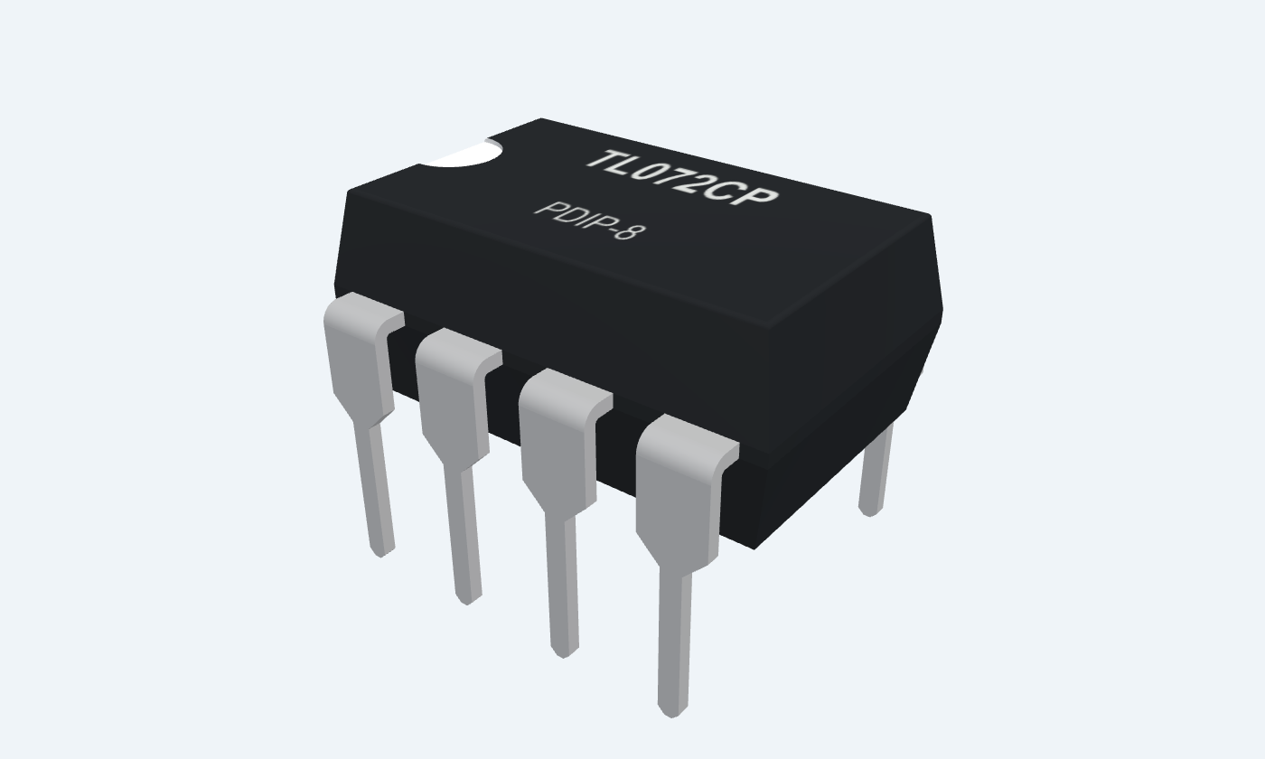
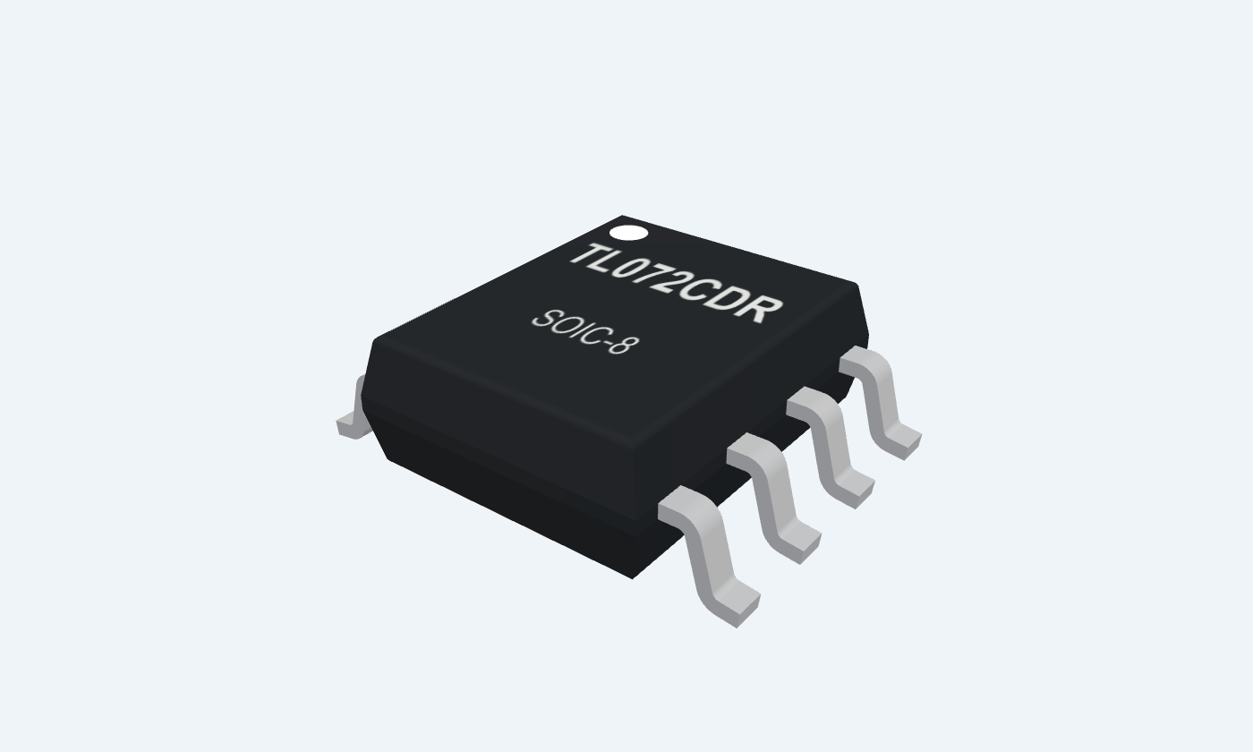
Two high-impedance analog channels in one compact IC.
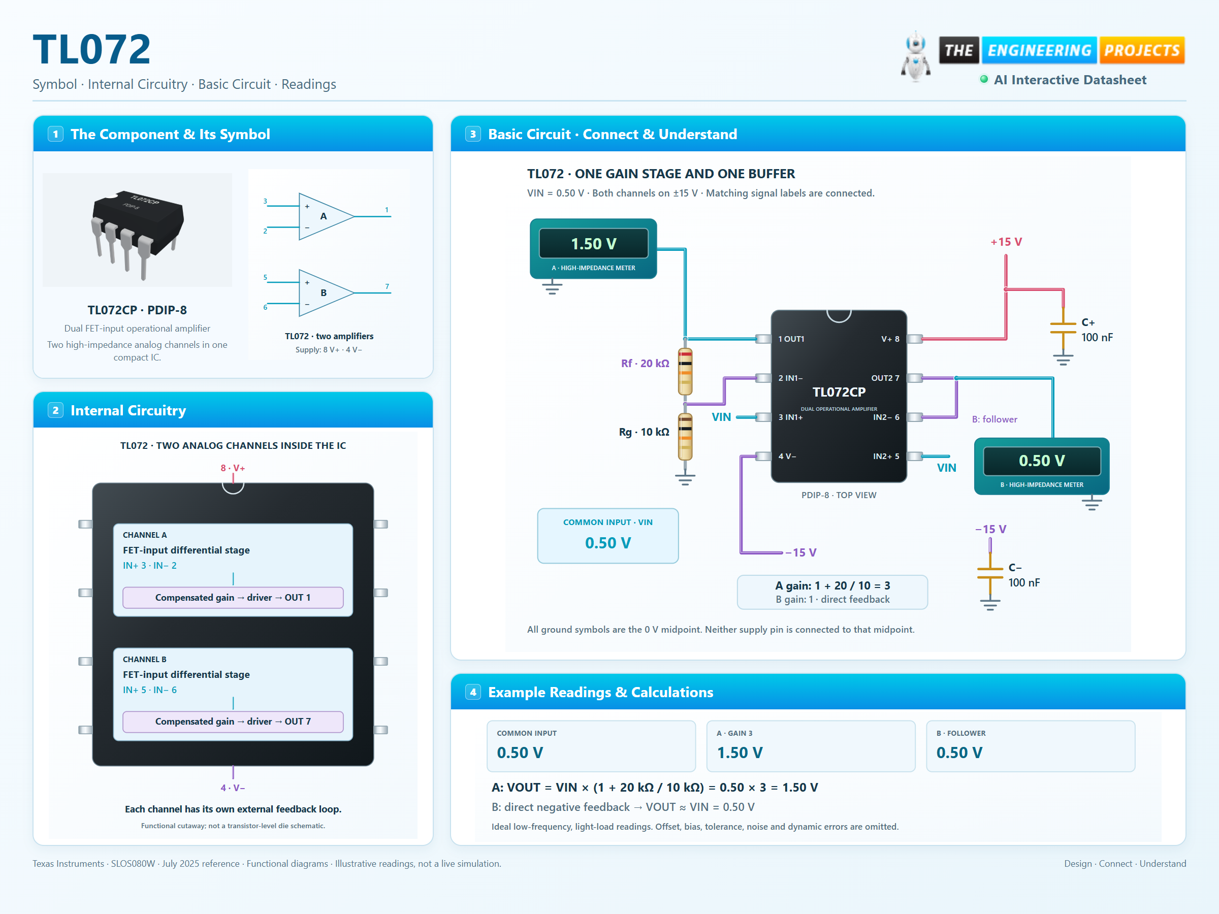
TL072 integrates two FET-input operational amplifiers. Each channel compares a pair of input voltages and uses external negative feedback to control its gain. The physical example uses channel A as a gain-of-three amplifier and channel B as a voltage follower. A shared 0.50 V input gives ideal outputs of 1.50 V and 0.50 V from a ±15 V supply. This page follows TI’s July 2025 reference for the C-grade P and D packages. Its revised P/D specifications differ from the legacy PS package; the manufacturer’s package-specific columns are kept separate.
Click a lead or use the arrow keys. Top view
Channel A output.
Return to IN1− through 20 kΩ; connect a high-impedance meter.
Channel A negative-feedback node.
Join 20 kΩ from OUT1 and 10 kΩ to signal ground.
Channel A signal input.
Apply VIN = 0.50 V relative to the 0 V midpoint.
Negative rail shared by both amplifiers.
Connect −15 V; bypass locally to 0 V with 100 nF.
Channel B signal input.
Connect to the same VIN in the illustrated follower.
Channel B feedback input.
Connect directly to OUT2 pin 7.
Channel B output.
Connect to IN2−; leave unloaded or use a high-impedance instrument.
Positive rail shared by both amplifiers.
Connect +15 V; bypass locally to 0 V with 100 nF.
Dual FET-input operational amplifier
High input impedance suits voltage buffering and active filters. Each channel needs its own negative-feedback path.
TL072CP
Key parameters and their test conditions
Follows the selected physical package
Select a pin to open its function, electrical notes and wiring guidance.
The FET input stage draws very little bias current at room temperature. Source resistance, board leakage and temperature still affect the input error.
Channel A uses 20 kΩ feedback and 10 kΩ to the 0 V midpoint, giving a gain of three. Channel B directly feeds its output back to its negative input, giving unity gain.
With a 0.50 V input, the ideal outputs are 1.50 V and 0.50 V. Real output also depends on input offset, resistor accuracy, loading, noise and signal frequency.
Both channels share the supply rails but have independent feedback paths. The diagram shows a low-frequency, light-load example; use the specified limits for your actual circuit.
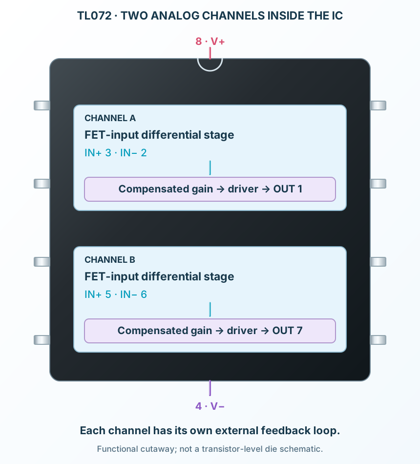
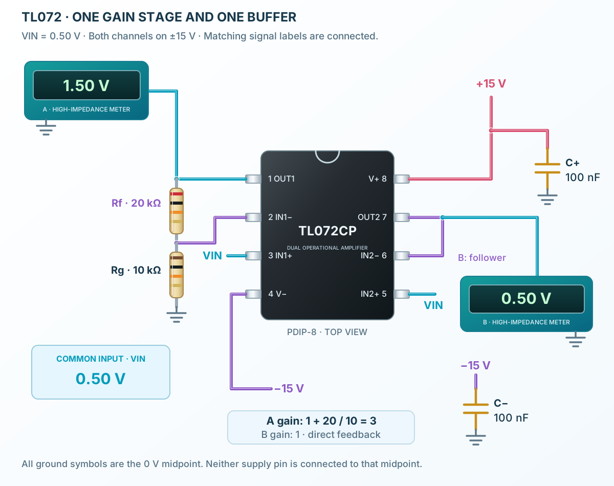
Select a pin to explore its function and connection.
| Pin | Signal | Type | Function |
|---|---|---|---|
| OUT1 | Analog output | Channel A output. | |
| IN1− | Inverting input | Channel A negative-feedback node. | |
| IN1+ | Non-inverting input | Channel A signal input. | |
| V− | Negative supply | Negative rail shared by both amplifiers. | |
| IN2+ | Non-inverting input | Channel B signal input. | |
| IN2− | Inverting input | Channel B feedback input. | |
| OUT2 | Analog output | Channel B output. | |
| V+ | Positive supply | Positive rail shared by both amplifiers. |
No pins match. Try a signal name or choose All pins.
TI TL072C · P/D package columns
| Parameter | Value | Conditions / notes |
|---|---|---|
| Total supply span | 4.5–40 V | V+ minus V−; Rev W, all except NS/PS/M |
| Ambient temperature | 0 to +70°C | TL072C grade |
| Recommended input range | V− + 4 V to V+ + 0.1 V | Observe supply and signal restrictions |
| Example supply | +15 V / −15 V | 0 V is the midpoint |
| Legacy PS package | 10–30 V total supply | Different column; not the package illustrated here |
No specifications match. Try a parameter name or a unit.
Values follow the stated revision and package. Do not apply current P/D limits to an unidentified older die.
±15 V · 25°C unless stated
| Parameter | Value | Conditions / notes |
|---|---|---|
| Input offset voltage | 3 mV typical; 10 mV maximum | TL072C; RS = 50 Ω |
| Input offset, full temperature | 13 mV maximum | 0–70°C |
| Input bias current | 65 pA typical; 200 pA maximum | 7 nA maximum over temperature |
| Input offset current | 5 pA typical; 100 pA maximum | 10 nA maximum over temperature |
| Supply current per amplifier | 1.4 mA typical; 2.5 mA maximum | No load; output at 0 V |
| Common-mode range | ±11 V minimum; −12 to +15 V typical | ±15 V test supply |
| Output swing | ±12 V minimum; ±13.5 V typical | RL = 10 kΩ |
No specifications match. Try a parameter name or a unit.
Typical values describe representative devices; use specified limits for error budgets.
TI Rev W · P/D packages
| Parameter | Value | Conditions / notes |
|---|---|---|
| Gain-bandwidth product | 5.25 MHz typical | P/D package column |
| Slew rate | 8 V/µs minimum; 20 V/µs typical | 10 V input; CL = 100 pF; RL = 2 kΩ |
| Input voltage noise at 1 kHz | 37 nV/√Hz typical | All except PS/NS/M |
| Input voltage noise at 10 kHz | 21 nV/√Hz typical | P/D package column |
| Phase margin | 56° typical | Gain +1; RL = 10 kΩ; CL = 20 pF |
No specifications match. Try a parameter name or a unit.
Bandwidth, slew rate and settling behavior are different limits; check all three for a changing signal.
±15 V rails · 0 V signal reference
| Parameter | Value | Conditions / notes |
|---|---|---|
| Input VIN | 0.50 V | Pins 3 and 5; common signal ground |
| Channel A feedback | 20 kΩ | OUT1 pin 1 to IN1− pin 2 |
| Channel A ground resistor | 10 kΩ | IN1− pin 2 to 0 V |
| Channel A ideal output | 1.50 V | 0.50 × (1 + 20 / 10) |
| Channel B feedback | Direct connection | OUT2 pin 7 to IN2− pin 6 |
| Channel B ideal output | 0.50 V | Unity-gain follower |
| Bypass capacitors | 100 nF per rail | Each supply rail to the 0 V midpoint |
No specifications match. Try a parameter name or a unit.
The 0 V reference is not the negative supply pin. Keep both rail-bypass loops short.
TL072CP · PDIP-8
| Parameter | Value | Conditions / notes |
|---|---|---|
| Lead pitch | 2.54 mm | Through-hole |
| Channel A | OUT1 1; IN1− 2; IN1+ 3 | Independent feedback loop |
| Channel B | IN2+ 5; IN2− 6; OUT2 7 | Independent feedback loop |
| Supply | V− 4; V+ 8 | Shared by both channels |
| Package orientation | Top view; pin 1 at the marker | Counterclockwise numbering |
No specifications match. Try a parameter name or a unit.
This dual-amplifier pinout differs from single amplifiers such as TL081 or LM741.
Buffer suitable high-resistance signal sources with attention to input leakage and common-mode range.
Manufacturer application guideUse separate feedback networks to build two filter stages, or a filter and an output buffer.
Manufacturer application guideBuild gain or mixing stages with appropriate coupling, supply decoupling and load headroom.
Manufacturer application guideFind TL072 in the Components Library to place its schematic symbol and connect its pins.
Reference page · circuit simulation model not yet availableOpen ProTech