 BETA
Single JFET-input operational amplifier
TL081 Working Principle
Learn how TL081 works with an illustrated explanation and practical readings.
Package view
TL081 at a glance
Follow the labeled connections and functional stages
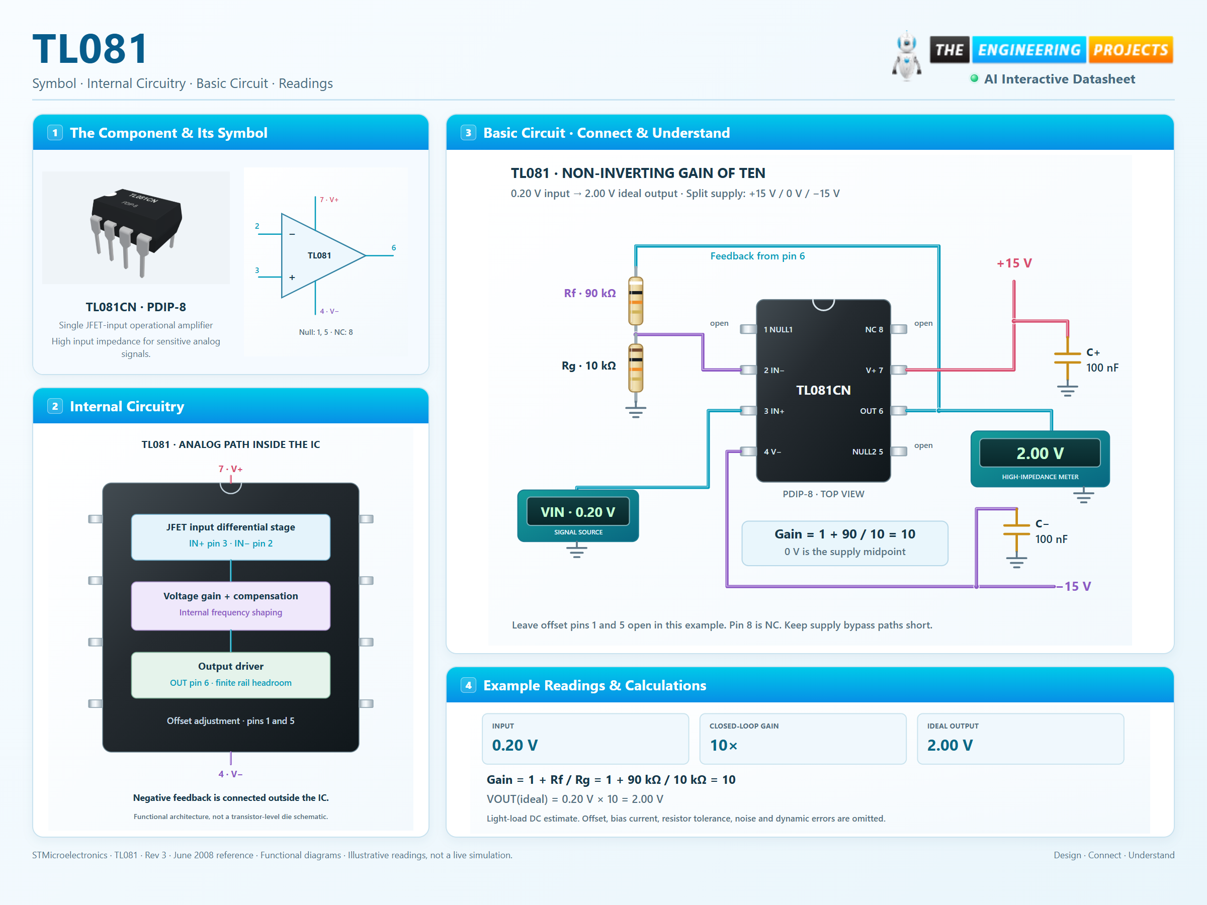
How it works
3 stages · Explore one step at a time
Sense with JFET inputs
The differential input stage has a high input impedance. Leakage still rises with temperature, so a high-impedance source needs careful board cleanliness and bias analysis.
Close the feedback loop
A 90 kΩ resistor returns the output to IN− and a 10 kΩ resistor connects that node to 0 V. Their ratio sets a nominal non-inverting gain of ten.
Allow headroom and bandwidth
The amplifier needs input and output headroom. At higher frequencies, gain-bandwidth and slew rate limit the signal independently of the resistor ratio.
Step 1 of 3