 BETA
Compare REF
The error amplifier compares REF against the internal reference.
Explore the internal circuitry and functional stages of TL431.
Reference, error amplifier and controlled shunt path.
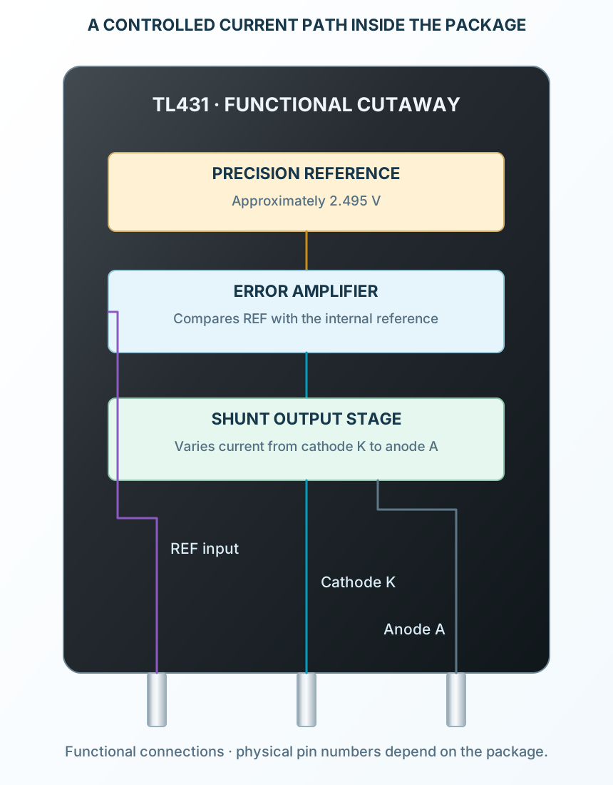
Select a stage to see its role and connections
The error amplifier compares REF against the internal reference.
The output stage sinks more or less current from K to A.
The external divider and feed resistor make that current regulate the output.