 BETA
Wire the load
Connect the coil from +12 V to O1 pin 18 and join pin 9 to the common return.
Build a basic ULN2803A circuit with labeled pins, component values and connection guidance.
A physical 18-pin array switches the low side of a 12 V coil.
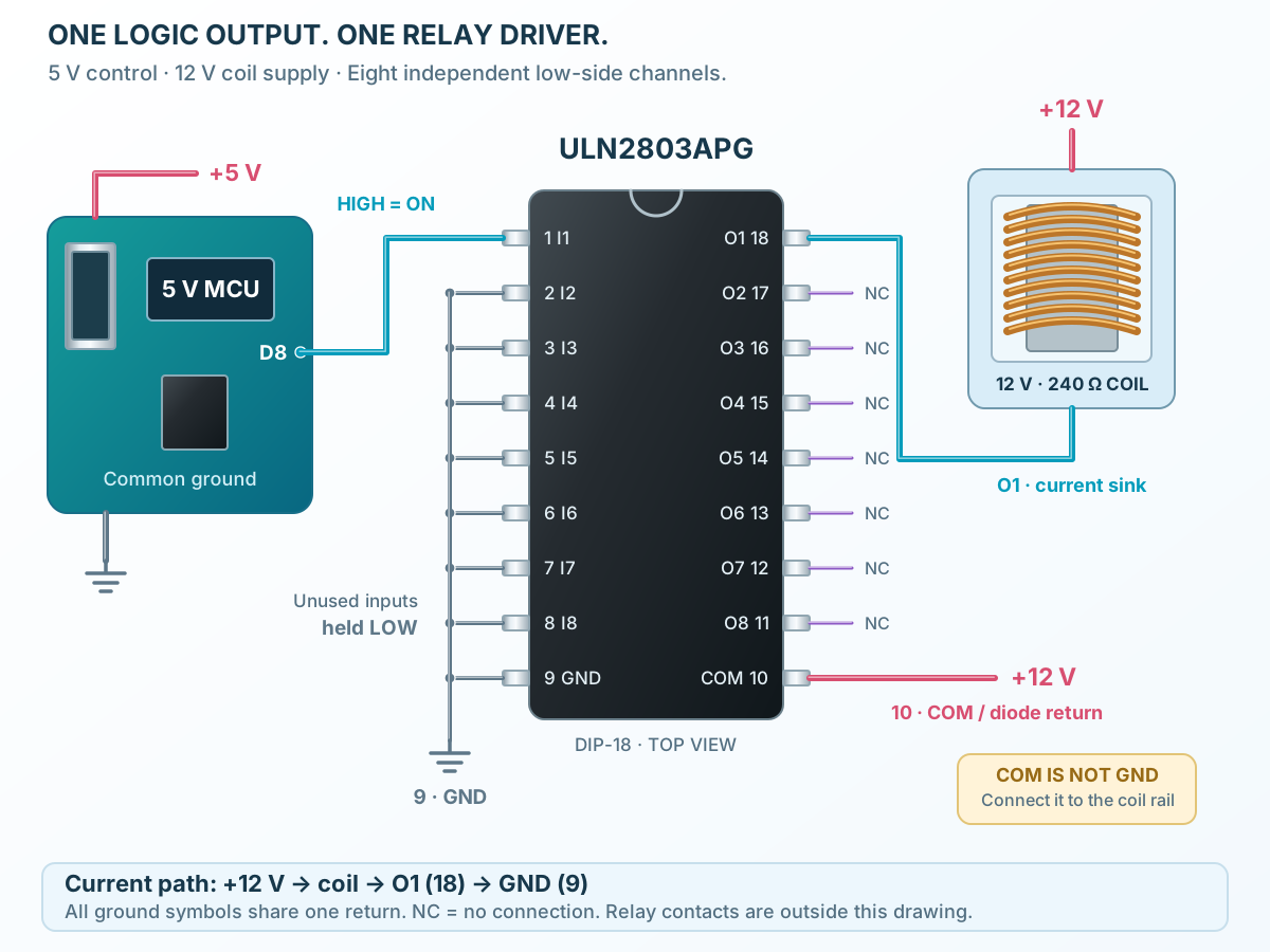
Follow the component values and pin connections
Connect the coil from +12 V to O1 pin 18 and join pin 9 to the common return.
Connect COM pin 10 to +12 V at the load supply.
Drive I1 pin 1 HIGH to energize the coil and LOW to release it. Hold unused inputs LOW.