 BETA
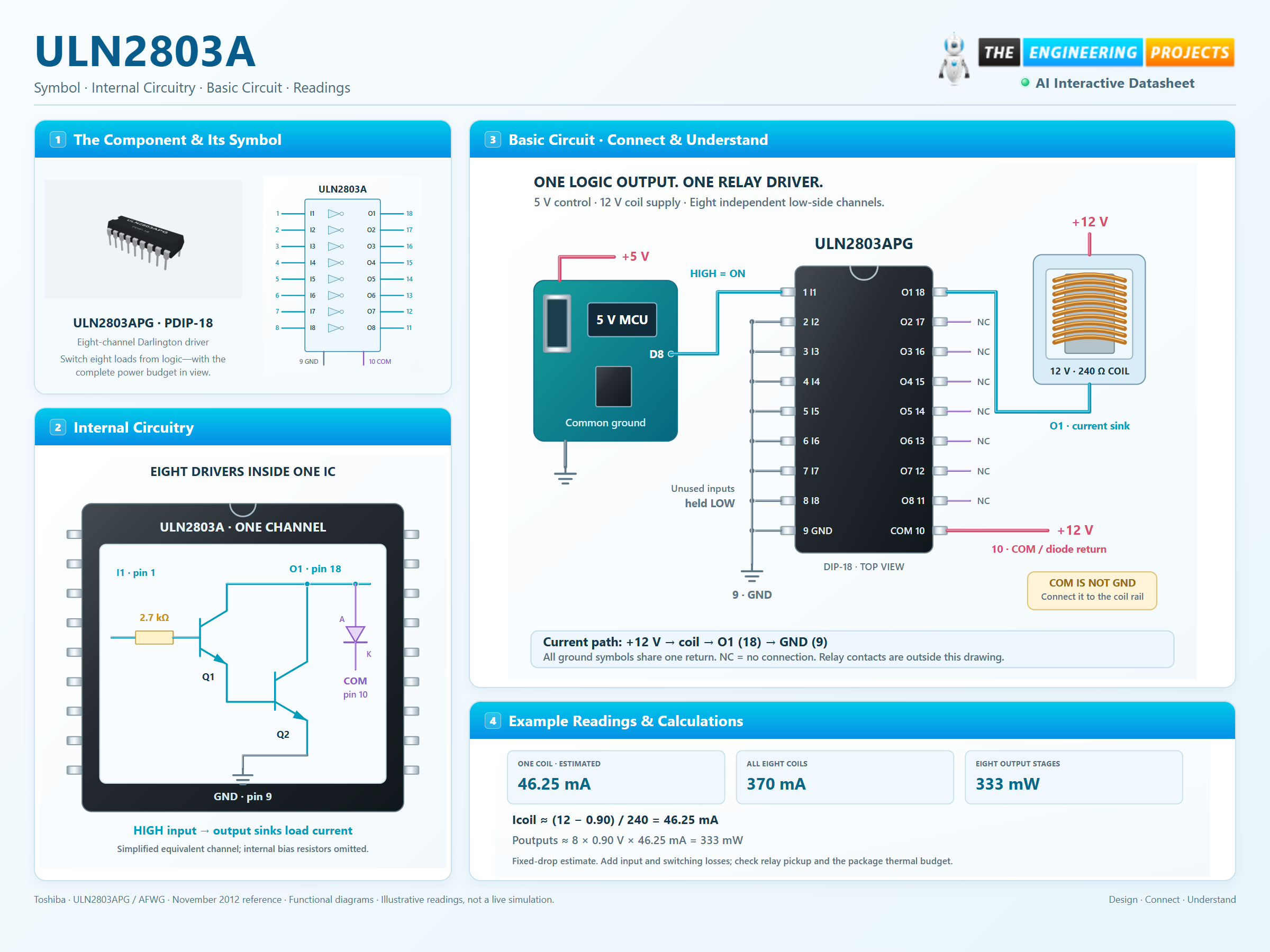
ULN2803A Working Principle
Learn how ULN2803A works with an illustrated explanation and practical readings.
ULN2803A at a glance
Follow the labeled connections and functional stages
How it works
3 stages · Explore one step at a time
Apply a logic level
Input current passes through the internal resistor and drives a pair of transistors. A HIGH input enables its corresponding collector sink.
Complete the load path
Current flows from the external positive supply, through the load, through the output transistor and back to pin 9.
Account for turn-off and heat
Coil current returns through the internal diode to COM after switch-off. Add dissipation from every active channel and consider the selected package and board.
Switch 8 loads independently
Click an input. Follow its collector current and the combined power budget.
Enable JavaScript to try the drivers.
Illustrative DC loads: 240 Ω coils, a 12 V rail and a fixed 0.90 V driver drop. COM is tied to the coil rail. The calculation excludes input-stage power, flyback transients, relay mechanics and temperature rise; it is not a safe-current guarantee.