Real View
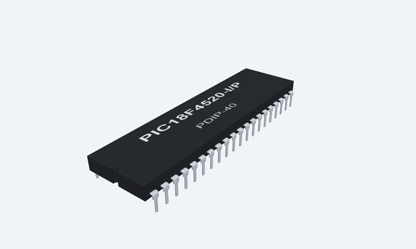
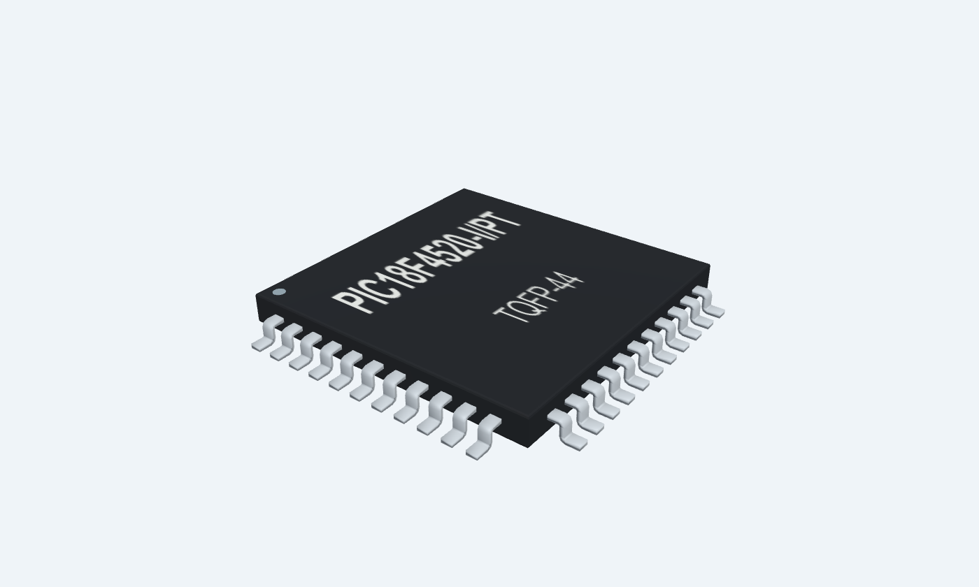
More memory, flexible clocks and carefully shared peripheral pins.
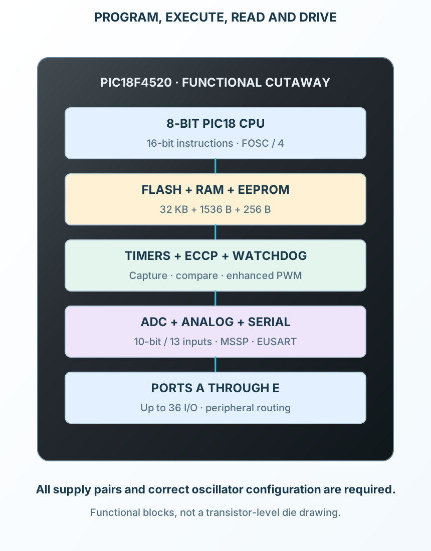
PIC18F4520 is an eight-bit microcontroller with 32 KB of Flash program memory, 1536 bytes of RAM and 256 bytes of data EEPROM. Its PIC18 core adds an eight-by-eight hardware multiplier, interrupt priorities and output latch registers. Up to 36 I/O lines share connections with timers, communication interfaces and a thirteen-channel ADC. The selected F-device operates from 4.2 to 5.5 V; the LF variant has different low-voltage limits. An internal oscillator can supply 31 kHz through 8 MHz, with a PLL option for higher internal-clock operation. A 40 MHz external oscillator gives up to 10 million instruction cycles per second because the instruction clock is FOSC divided by four. The reference circuit uses regulated 5 V, the internal 8 MHz oscillator, both supply pairs, ICSP and a resistor-limited LED on RB0. Firmware must disable unwanted analog functions and configure latches, direction and clock selection. PDIP and TQFP use different physical pin numbers, which the package selector keeps mapped consistently.
Click a lead or use the arrow keys. Top view
Active-low reset and programming voltage input; RE3 is input-only when MCLR is disabled.
10 kΩ pull-up to 5 V; preserve ICSP VPP access.
Multiplexed port and named peripheral functions. Set direction, analog selection and peripheral routing explicitly.
Use supply-compatible signals and define unused inputs.
ADCON1 selects analog/digital functions; AN8–AN12 are on PORTB.
Multiplexed port and named peripheral functions. Set direction, analog selection and peripheral routing explicitly.
Use supply-compatible signals and define unused inputs.
ADCON1 selects analog/digital functions; AN8–AN12 are on PORTB.
Multiplexed port and named peripheral functions. Set direction, analog selection and peripheral routing explicitly.
Use supply-compatible signals and define unused inputs.
ADCON1 selects analog/digital functions; AN8–AN12 are on PORTB.
Multiplexed port and named peripheral functions. Set direction, analog selection and peripheral routing explicitly.
Use supply-compatible signals and define unused inputs.
ADCON1 selects analog/digital functions; AN8–AN12 are on PORTB.
Multiplexed port and named peripheral functions. Set direction, analog selection and peripheral routing explicitly.
Use supply-compatible signals and define unused inputs.
Multiplexed port and named peripheral functions. Set direction, analog selection and peripheral routing explicitly.
Use supply-compatible signals and define unused inputs.
ADCON1 selects analog/digital functions; AN8–AN12 are on PORTB.
Multiplexed port and named peripheral functions. Set direction, analog selection and peripheral routing explicitly.
Use supply-compatible signals and define unused inputs.
ADCON1 selects analog/digital functions; AN8–AN12 are on PORTB.
Multiplexed port and named peripheral functions. Set direction, analog selection and peripheral routing explicitly.
Use supply-compatible signals and define unused inputs.
ADCON1 selects analog/digital functions; AN8–AN12 are on PORTB.
Multiplexed port and named peripheral functions. Set direction, analog selection and peripheral routing explicitly.
Use supply-compatible signals and define unused inputs.
ADCON1 selects analog/digital functions; AN8–AN12 are on PORTB.
Positive supply; connect both VDD pins.
Regulated 5 V with a local 100 nF capacitor to VSS.
Ground return; connect both VSS pins.
Common ground plane.
External oscillator or GPIO, depending on the oscillator configuration.
The internal 8 MHz example leaves these available as RA7 / RA6 with the matching configuration.
External oscillator or GPIO, depending on the oscillator configuration.
The internal 8 MHz example leaves these available as RA7 / RA6 with the matching configuration.
Multiplexed port and named peripheral functions. Set direction, analog selection and peripheral routing explicitly.
Use supply-compatible signals and define unused inputs.
Multiplexed port and named peripheral functions. Set direction, analog selection and peripheral routing explicitly.
Use supply-compatible signals and define unused inputs.
CCP2MX selects RC1 or RB3 for CCP2.
Multiplexed port and named peripheral functions. Set direction, analog selection and peripheral routing explicitly.
Use supply-compatible signals and define unused inputs.
Multiplexed port and named peripheral functions. Set direction, analog selection and peripheral routing explicitly.
Use supply-compatible signals and define unused inputs.
Multiplexed port and named peripheral functions. Set direction, analog selection and peripheral routing explicitly.
Use supply-compatible signals and define unused inputs.
Multiplexed port and named peripheral functions. Set direction, analog selection and peripheral routing explicitly.
Use supply-compatible signals and define unused inputs.
Multiplexed port and named peripheral functions. Set direction, analog selection and peripheral routing explicitly.
Use supply-compatible signals and define unused inputs.
Multiplexed port and named peripheral functions. Set direction, analog selection and peripheral routing explicitly.
Use supply-compatible signals and define unused inputs.
Multiplexed port and named peripheral functions. Set direction, analog selection and peripheral routing explicitly.
Use supply-compatible signals and define unused inputs.
Multiplexed port and named peripheral functions. Set direction, analog selection and peripheral routing explicitly.
Use supply-compatible signals and define unused inputs.
Multiplexed port and named peripheral functions. Set direction, analog selection and peripheral routing explicitly.
Use supply-compatible signals and define unused inputs.
Multiplexed port and named peripheral functions. Set direction, analog selection and peripheral routing explicitly.
Use supply-compatible signals and define unused inputs.
Multiplexed port and named peripheral functions. Set direction, analog selection and peripheral routing explicitly.
Use supply-compatible signals and define unused inputs.
Multiplexed port and named peripheral functions. Set direction, analog selection and peripheral routing explicitly.
Use supply-compatible signals and define unused inputs.
Multiplexed port and named peripheral functions. Set direction, analog selection and peripheral routing explicitly.
Use supply-compatible signals and define unused inputs.
Multiplexed port and named peripheral functions. Set direction, analog selection and peripheral routing explicitly.
Use supply-compatible signals and define unused inputs.
Ground return; connect both VSS pins.
Common ground plane.
Positive supply; connect both VDD pins.
Regulated 5 V with a local 100 nF capacitor to VSS.
Multiplexed port and named peripheral functions. Set direction, analog selection and peripheral routing explicitly.
Example: RB0 through 1 kΩ and a red LED to ground.
ADCON1 selects analog/digital functions; AN8–AN12 are on PORTB.
Multiplexed port and named peripheral functions. Set direction, analog selection and peripheral routing explicitly.
Use supply-compatible signals and define unused inputs.
ADCON1 selects analog/digital functions; AN8–AN12 are on PORTB.
Multiplexed port and named peripheral functions. Set direction, analog selection and peripheral routing explicitly.
Use supply-compatible signals and define unused inputs.
ADCON1 selects analog/digital functions; AN8–AN12 are on PORTB.
Multiplexed port and named peripheral functions. Set direction, analog selection and peripheral routing explicitly.
Use supply-compatible signals and define unused inputs.
CCP2 on RB3 is the alternate CCP2MX routing.
Multiplexed port and named peripheral functions. Set direction, analog selection and peripheral routing explicitly.
Use supply-compatible signals and define unused inputs.
ADCON1 selects analog/digital functions; AN8–AN12 are on PORTB.
Multiplexed port and named peripheral functions. Set direction, analog selection and peripheral routing explicitly.
Use supply-compatible signals and define unused inputs.
RB5 is PGM when low-voltage programming is enabled; define it or deliberately disable LVP.
Multiplexed port and named peripheral functions. Set direction, analog selection and peripheral routing explicitly.
Connect to ICSP programmer with VPP, VDD and VSS.
Multiplexed port and named peripheral functions. Set direction, analog selection and peripheral routing explicitly.
Connect to ICSP programmer with VPP, VDD and VSS.
Unused physical lead in the TQFP package.
Leave unconnected.
Unused physical lead in the TQFP package.
Leave unconnected.
Unused physical lead in the TQFP package.
Leave unconnected.
Unused physical lead in the TQFP package.
Leave unconnected.
8-bit PIC18 microcontroller with 40/44-pin packages
Ports share analog, timing and communication functions; the selected configuration determines which function reaches each pad.
PIC18F4520-I/P
Key parameters and their test conditions
Follows the selected physical package
Select a pin to open its function, electrical notes and wiring guidance.
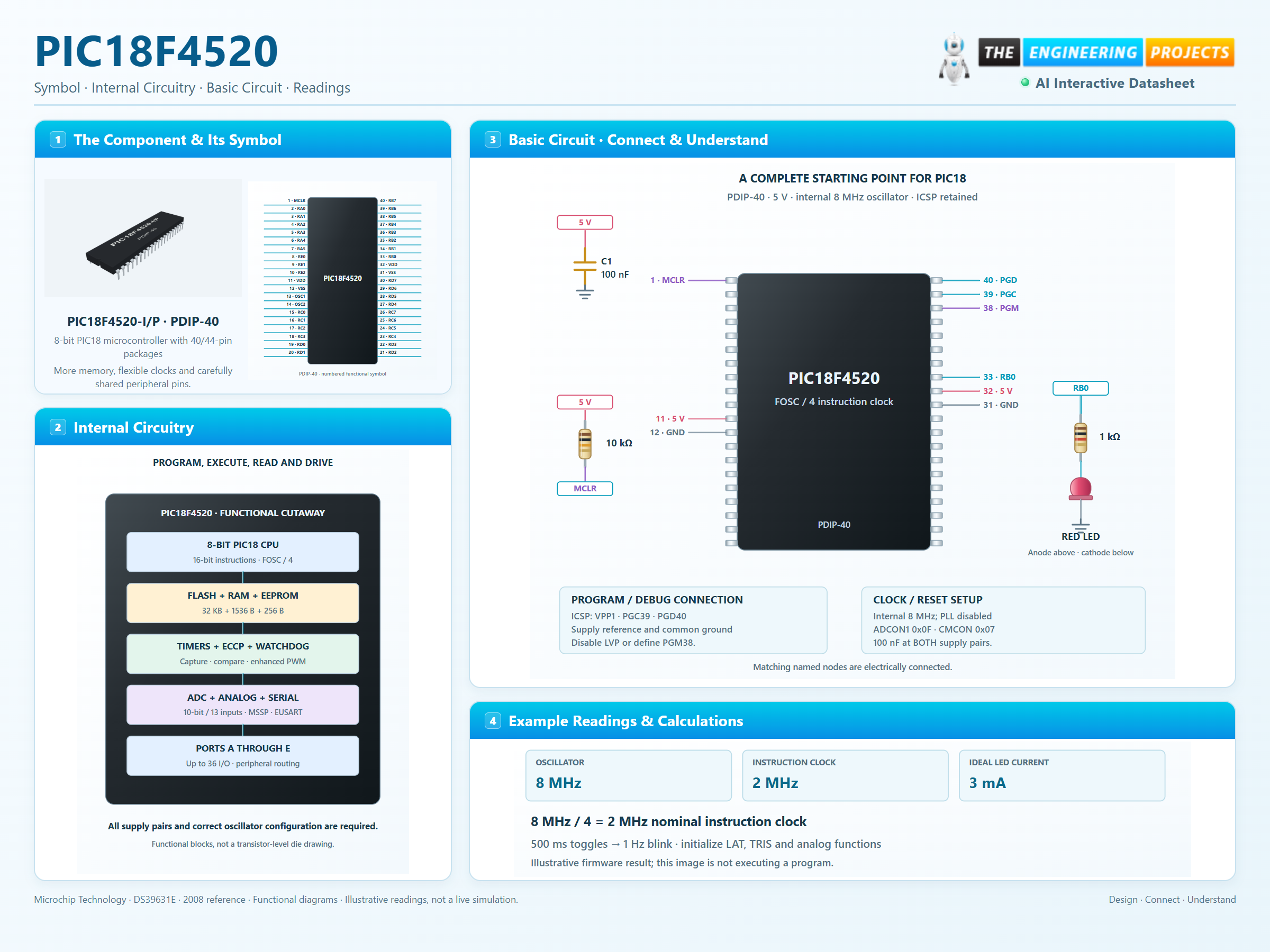
Connect both VDD and VSS pairs with nearby bypass capacitors.
Select the internal oscillator and its 8 MHz setting.
Set analog functions, output latches and direction before running the example.
The 8 MHz internal-clock example has a nominal 2 MHz instruction clock. Toggle every 500 ms for a 1 Hz full blink cycle.
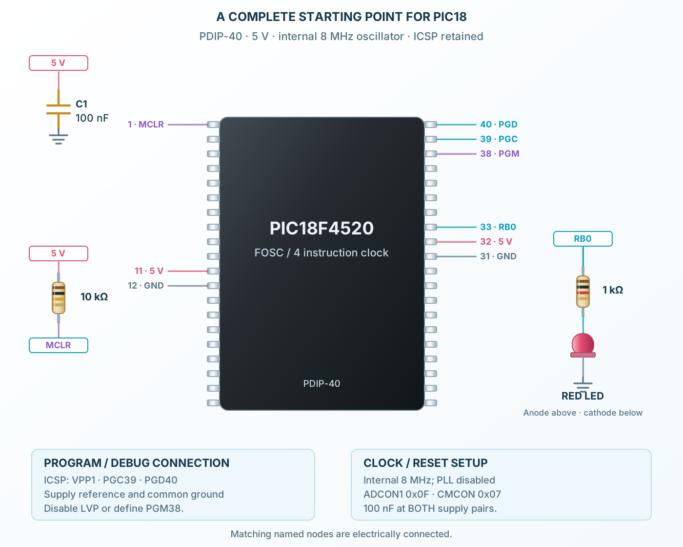
Select a pin to explore its function and connection.
| Pin | Signal | Type | Function |
|---|---|---|---|
| MCLR / VPP / RE3 | Reset / programming | Active-low reset and programming voltage input; RE3 is input-only when MCLR is disabled. | |
| RA0 / AN0 | GPIO / peripheral | Multiplexed port and named peripheral functions. Set direction, analog selection and peripheral routing explicitly. | |
| RA1 / AN1 | GPIO / peripheral | Multiplexed port and named peripheral functions. Set direction, analog selection and peripheral routing explicitly. | |
| RA2 / AN2 / VREF− / CVREF | GPIO / peripheral | Multiplexed port and named peripheral functions. Set direction, analog selection and peripheral routing explicitly. | |
| RA3 / AN3 / VREF+ | GPIO / peripheral | Multiplexed port and named peripheral functions. Set direction, analog selection and peripheral routing explicitly. | |
| RA4 / T0CKI / C1OUT | GPIO / peripheral | Multiplexed port and named peripheral functions. Set direction, analog selection and peripheral routing explicitly. | |
| RA5 / AN4 / SS / HLVDIN / C2OUT | GPIO / peripheral | Multiplexed port and named peripheral functions. Set direction, analog selection and peripheral routing explicitly. | |
| RE0 / RD / AN5 | GPIO / peripheral | Multiplexed port and named peripheral functions. Set direction, analog selection and peripheral routing explicitly. | |
| RE1 / WR / AN6 | GPIO / peripheral | Multiplexed port and named peripheral functions. Set direction, analog selection and peripheral routing explicitly. | |
| RE2 / CS / AN7 | GPIO / peripheral | Multiplexed port and named peripheral functions. Set direction, analog selection and peripheral routing explicitly. | |
| VDD | Supply | Positive supply; connect both VDD pins. | |
| VSS | Supply | Ground return; connect both VSS pins. | |
| OSC1 / CLKI / RA7 | Oscillator / GPIO | External oscillator or GPIO, depending on the oscillator configuration. | |
| OSC2 / CLKO / RA6 | Oscillator / GPIO | External oscillator or GPIO, depending on the oscillator configuration. | |
| RC0 / T1OSO / T13CKI | GPIO / peripheral | Multiplexed port and named peripheral functions. Set direction, analog selection and peripheral routing explicitly. | |
| RC1 / T1OSI / CCP2 | GPIO / peripheral | Multiplexed port and named peripheral functions. Set direction, analog selection and peripheral routing explicitly. | |
| RC2 / CCP1 / P1A | GPIO / peripheral | Multiplexed port and named peripheral functions. Set direction, analog selection and peripheral routing explicitly. | |
| RC3 / SCK / SCL | GPIO / peripheral | Multiplexed port and named peripheral functions. Set direction, analog selection and peripheral routing explicitly. | |
| RD0 / PSP0 | GPIO / peripheral | Multiplexed port and named peripheral functions. Set direction, analog selection and peripheral routing explicitly. | |
| RD1 / PSP1 | GPIO / peripheral | Multiplexed port and named peripheral functions. Set direction, analog selection and peripheral routing explicitly. | |
| RD2 / PSP2 | GPIO / peripheral | Multiplexed port and named peripheral functions. Set direction, analog selection and peripheral routing explicitly. | |
| RD3 / PSP3 | GPIO / peripheral | Multiplexed port and named peripheral functions. Set direction, analog selection and peripheral routing explicitly. | |
| RC4 / SDI / SDA | GPIO / peripheral | Multiplexed port and named peripheral functions. Set direction, analog selection and peripheral routing explicitly. | |
| RC5 / SDO | GPIO / peripheral | Multiplexed port and named peripheral functions. Set direction, analog selection and peripheral routing explicitly. | |
| RC6 / TX / CK | GPIO / peripheral | Multiplexed port and named peripheral functions. Set direction, analog selection and peripheral routing explicitly. | |
| RC7 / RX / DT | GPIO / peripheral | Multiplexed port and named peripheral functions. Set direction, analog selection and peripheral routing explicitly. | |
| RD4 / PSP4 | GPIO / peripheral | Multiplexed port and named peripheral functions. Set direction, analog selection and peripheral routing explicitly. | |
| RD5 / PSP5 / P1B | GPIO / peripheral | Multiplexed port and named peripheral functions. Set direction, analog selection and peripheral routing explicitly. | |
| RD6 / PSP6 / P1C | GPIO / peripheral | Multiplexed port and named peripheral functions. Set direction, analog selection and peripheral routing explicitly. | |
| RD7 / PSP7 / P1D | GPIO / peripheral | Multiplexed port and named peripheral functions. Set direction, analog selection and peripheral routing explicitly. | |
| VSS | Supply | Ground return; connect both VSS pins. | |
| VDD | Supply | Positive supply; connect both VDD pins. | |
| RB0 / INT0 / FLT0 / AN12 | GPIO / peripheral | Multiplexed port and named peripheral functions. Set direction, analog selection and peripheral routing explicitly. | |
| RB1 / INT1 / AN10 | GPIO / peripheral | Multiplexed port and named peripheral functions. Set direction, analog selection and peripheral routing explicitly. | |
| RB2 / INT2 / AN8 | GPIO / peripheral | Multiplexed port and named peripheral functions. Set direction, analog selection and peripheral routing explicitly. | |
| RB3 / AN9 / CCP2 | GPIO / peripheral | Multiplexed port and named peripheral functions. Set direction, analog selection and peripheral routing explicitly. | |
| RB4 / KBI0 / AN11 | GPIO / peripheral | Multiplexed port and named peripheral functions. Set direction, analog selection and peripheral routing explicitly. | |
| RB5 / KBI1 / PGM | GPIO / peripheral | Multiplexed port and named peripheral functions. Set direction, analog selection and peripheral routing explicitly. | |
| RB6 / KBI2 / PGC | GPIO / peripheral | Multiplexed port and named peripheral functions. Set direction, analog selection and peripheral routing explicitly. | |
| RB7 / KBI3 / PGD | GPIO / peripheral | Multiplexed port and named peripheral functions. Set direction, analog selection and peripheral routing explicitly. | |
| NC | No connection | Unused physical lead in the TQFP package. | |
| NC | No connection | Unused physical lead in the TQFP package. | |
| NC | No connection | Unused physical lead in the TQFP package. | |
| NC | No connection | Unused physical lead in the TQFP package. |
No pins match. Try a signal name or choose All pins.
Selected PIC18F4520
| Parameter | Value | Conditions / notes |
|---|---|---|
| Program Flash | 32 KB | 16K 16-bit words; some instructions occupy two words |
| Data RAM | 1536 bytes | Access-bank and banked addressing |
| Data EEPROM | 256 bytes | Nonvolatile application storage |
| Hardware multiplier | 8 × 8 bits | Single instruction cycle multiply |
| Return stack | 31 levels | Hardware return-address stack |
| Instruction clock | FOSC / 4 | Up to 10 MIPS at 40 MHz |
No specifications match. Try a parameter name or a unit.
Instruction timing and branch costs still matter in software delays.
F-device industrial selection
| Parameter | Value | Conditions / notes |
|---|---|---|
| VDD range | 4.2–5.5 V | Use regulated 5 V in this example |
| PDIP supplies | VDD11/32; VSS12/31 | Connect and bypass both pairs |
| TQFP supplies | VDD7/28; VSS6/29 | Same functions, different physical numbers |
| MCLR / VPP | PDIP1; TQFP18 | 10 kΩ reset pull-up; ICSP access retained |
| RE3 | Input-only alternate function | Available when MCLR is disabled |
| Industrial temperature | −40 to +85°C | I-grade orderables |
No specifications match. Try a parameter name or a unit.
PIC18LF4520 low-voltage limits must not be substituted for the selected PIC18F4520.
Internal oscillator and external options
| Parameter | Value | Conditions / notes |
|---|---|---|
| Internal oscillator block | 31 kHz through 8 MHz | IRCF selects the nominal frequency |
| Internal example | 8 MHz, PLL disabled | 2 MHz nominal instruction clock |
| OSCCON example | 0x72 | IRCF=111; SCS selects the internal oscillator |
| Internal PLL option | Up to 32 MHz | Follow OSCTUNE and oscillator configuration requirements |
| Maximum external FOSC | 40 MHz | 10 MIPS instruction rate |
| RA6 / RA7 | Available with suitable internal-oscillator configuration | OSC2/OSC1 share these pads |
No specifications match. Try a parameter name or a unit.
Use the compiler clock setting and configuration bits that match the actual oscillator.
Avoid inherited assumptions from older PICs
| Parameter | Value | Conditions / notes |
|---|---|---|
| Maximum I/O | 36 lines | Includes RE3 input-only and oscillator-pin GPIO when available |
| TRIS | 1 input; 0 output | Set the output latch before enabling output |
| LAT registers | Use LATx for output updates | Avoid read-modify-write effects from reading pin levels |
| All-digital example | ADCON1 = 0x0F | AN0 through AN12 become digital |
| Comparators disabled | CMCON = 0x07 | Example uses ordinary GPIO |
| PORTB analog reset | PBADEN configuration matters | Explicitly initialize ADCON1 |
| CCP2 routing | RC1 or RB3 | Selected by CCP2MX |
No specifications match. Try a parameter name or a unit.
RA4 and RA5 capabilities must be read from this PIC18 device, not copied from PIC16F877A.
Multiplexed hardware functions
| Parameter | Value | Conditions / notes |
|---|---|---|
| ADC | 10-bit, 13 channels | AN0–AN12; references selectable |
| ADC acquisition | Set settling and conversion timing | Depends on source impedance, clock and reference |
| Timer0 | 8- or 16-bit | Programmable prescaler and clock source |
| Timer1 / Timer3 | 16-bit | Independent timing resources |
| Timer2 | 8-bit with period register | PWM timebase |
| ECCP1 / CCP2 | Enhanced PWM plus capture/compare/PWM | P1A–P1D share port pads |
| MSSP | SPI or I²C | RC3/RC4/RC5 and SS routing |
| EUSART | Synchronous or asynchronous | RC6 TX/CK and RC7 RX/DT |
| Comparators / HLVD | Two comparators and voltage detect | Selected analog functions |
No specifications match. Try a parameter name or a unit.
One pad cannot perform incompatible peripheral functions simultaneously.
Keep programming paths accessible
| Parameter | Value | Conditions / notes |
|---|---|---|
| PDIP ICSP | VPP1, PGC39, PGD40 | Add VDD and VSS reference |
| TQFP ICSP | VPP18, PGC16, PGD17 | Verify the package selector before wiring |
| LVP entry | RB5 / PGM | PDIP38; TQFP15 |
| LVP choice | Disable deliberately or define PGM | Do not copy PIC16 RB3/PGM wiring |
| Watchdog / brown-out | Configure intentionally | An enabled unserviced watchdog resets firmware |
| Internal-clock setup | INTIO configuration with RA6/RA7 as GPIO | Keep OSCTUNE PLL disabled for the 8 MHz example |
No specifications match. Try a parameter name or a unit.
Use a compatible programmer and keep programming voltage separate from normal GPIO levels.
PDIP-40, regulated 5 V
| Parameter | Value | Conditions / notes |
|---|---|---|
| Power | VDD11/32; VSS12/31 | 100 nF at each pair |
| Reset | MCLR1 with 10 kΩ to 5 V | ICSP VPP remains available |
| Clock | Internal 8 MHz | No crystal is required for this example |
| LED | RB0 pin33 → 1 kΩ → red LED → GND | About 3 mA for an ideal 2 V LED |
| Firmware initialization | ADCON1=0x0F; CMCON=0x07 | Initialize LATB0, then TRISB0=0 |
| Blink period | Toggle LATB0 every 500 ms | 1 Hz full cycle at the configured clock |
No specifications match. Try a parameter name or a unit.
The illustration is a firmware teaching circuit; timing readings are nominal and are not a running processor model.
Combine digital control with multiple analog channels.
Manufacturer application guideUse MSSP and EUSART for external devices.
Manufacturer application guideDrive external power stages through properly rated interfaces.
Manufacturer application guideFind PIC18F4520 in the Components Library to place its schematic symbol and connect its pins.
Reference page · circuit simulation model not yet availableOpen ProTech