STM32F103C8T632-bit Arm Cortex-M3 microcontroller
A 72 MHz controller with a compact, versatile peripheral set.
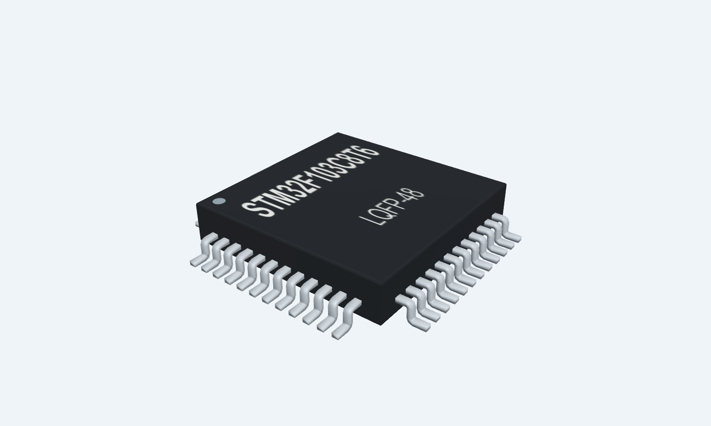
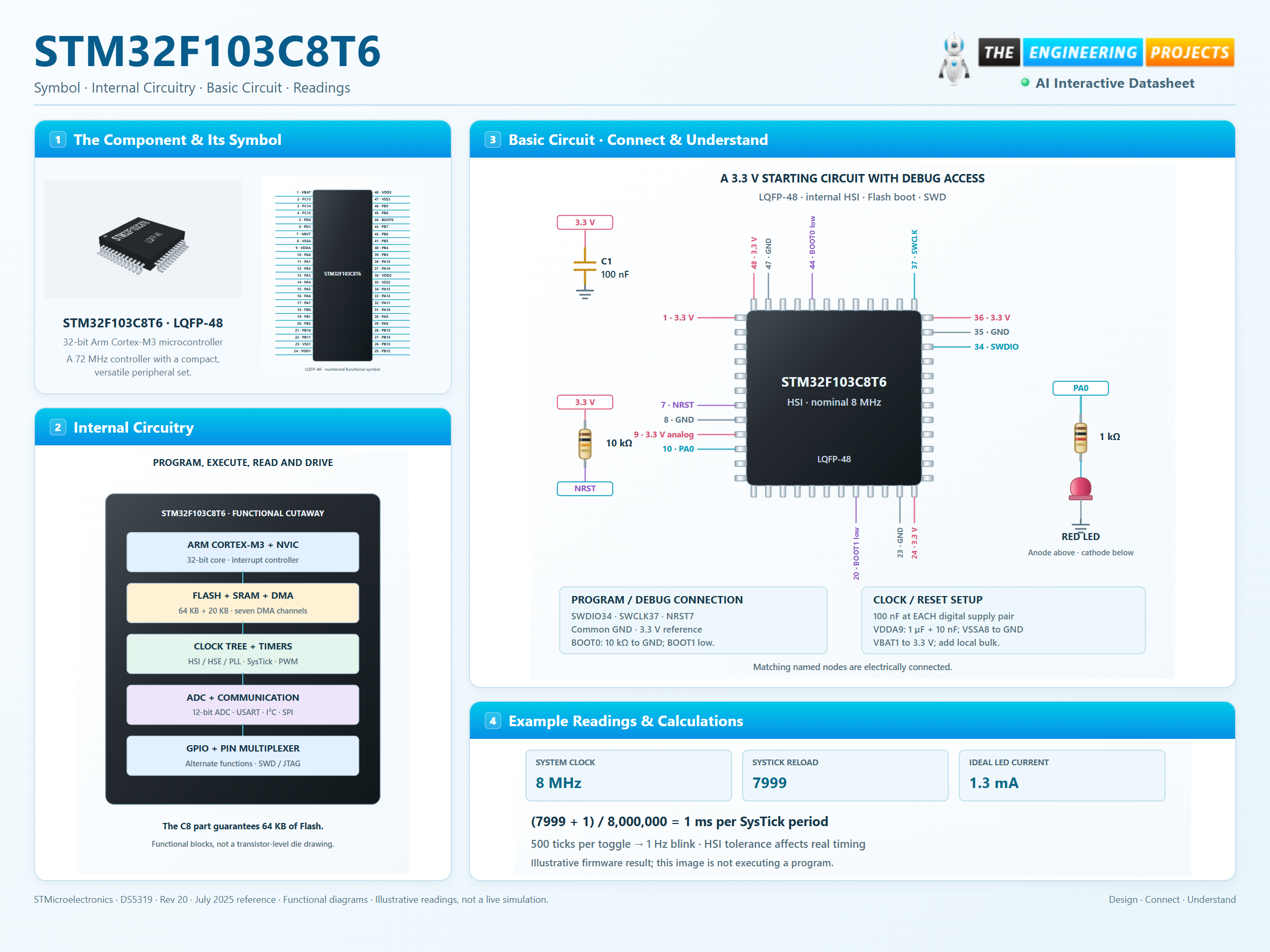
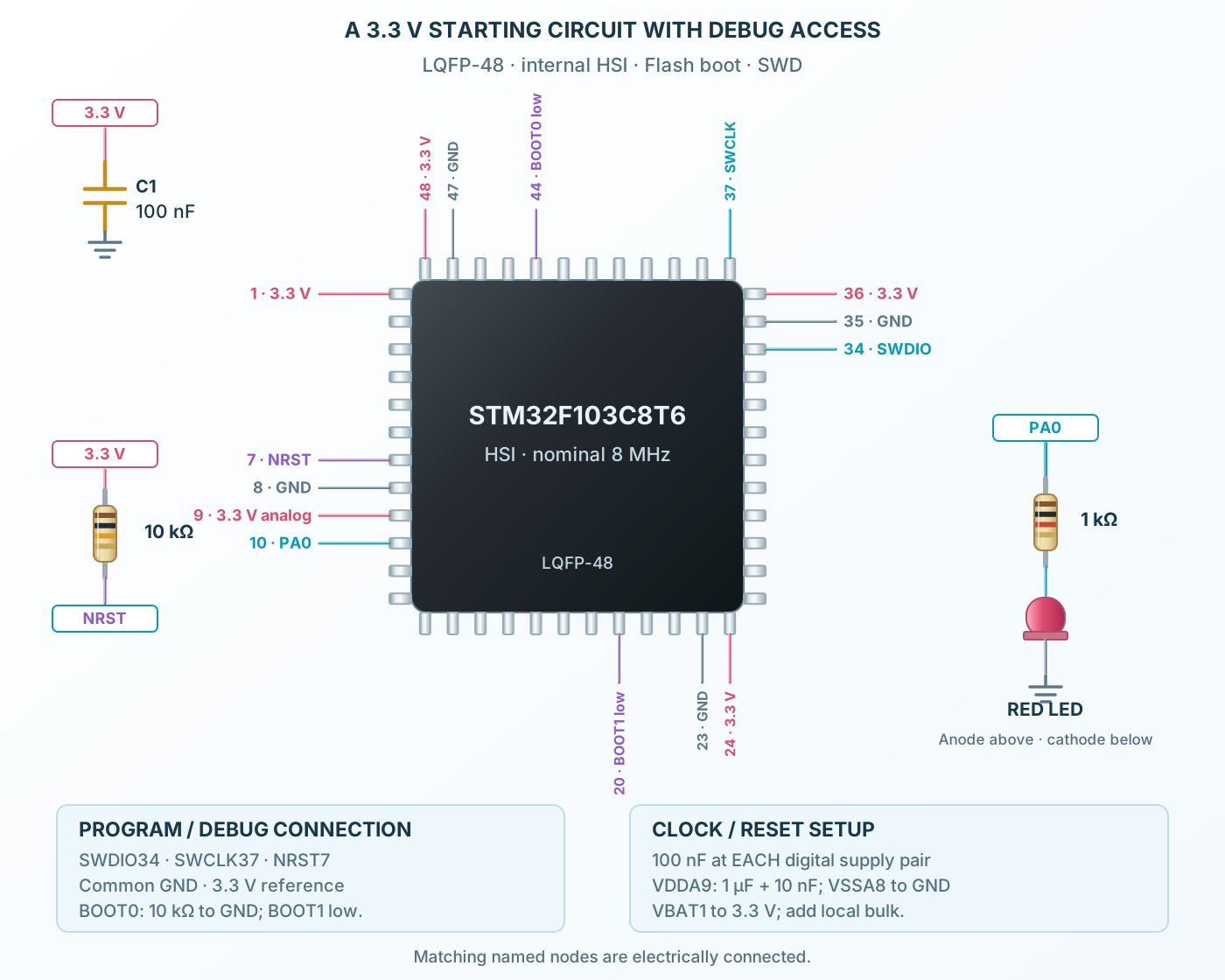
STM32F103C8T6 is a 32-bit Arm Cortex-M3 microcontroller in a 48-lead LQFP package. The C8 device has 64 KB of specified Flash and 20 KB of SRAM, with timers, DMA, serial interfaces and two twelve-bit ADCs. Its maximum system frequency is 72 MHz with a correctly configured clock tree. The part operates from 2.0 to 3.6 V, with additional analog supply conditions when using the ADC. Every digital supply pair, the analog rail and the backup input need deliberate connections. Some digital pins tolerate 5 V under specified conditions, but this does not apply to every pin or to analog inputs. The reference circuit uses 3.3 V and the reset-default 8 MHz internal oscillator, so its simple LED demonstration needs no external crystal. SWD remains accessible, BOOT0 is held low and firmware starts from Flash. Higher-speed, USB and precision-timing applications need their own reviewed clock configuration.

Digital, analog and backup suppliesDigital GPIO and alternate functionsOscillator connectionsReset and boot selectionADC-capable GPIOSWD / JTAG access
STM32F103C8T6LQFP-48Top view
Click a lead or use the arrow keys. Top view
PIN 1 · Digital, analog and backup supplies
SupplyVBAT
Function
Supply connection for the named power domain.
How to connect
Connect to 3.3 V when no separate backup battery is fitted.
Electrical note
Connect every supply domain; do not leave VDDA or VBAT floating.
PIN 2 · Digital GPIO and alternate functions
Multiplexed pinPC13 / TAMPER
Function
Multiplexed GPIO and the named default alternate function; remapping and peripheral configuration may change its use.
How to connect
Connect only to compatible signal levels and configure the pin mode.
Electrical note
PC13–PC15 have restricted drive: do not use as LED current sources; observe 3 mA switch and speed limits.
PIN 3 · Oscillator connections
Multiplexed pinPC14 / OSC32_IN
Function
GPIO multiplexed with the selected crystal oscillator function.
How to connect
Leave oscillator pins unused when running only from HSI; add correctly loaded crystals when selected.
Electrical note
PC13–PC15 have restricted drive: do not use as LED current sources; observe 3 mA switch and speed limits.
PIN 4 · Oscillator connections
Multiplexed pinPC15 / OSC32_OUT
Function
GPIO multiplexed with the selected crystal oscillator function.
How to connect
Leave oscillator pins unused when running only from HSI; add correctly loaded crystals when selected.
Electrical note
PC13–PC15 have restricted drive: do not use as LED current sources; observe 3 mA switch and speed limits.
PIN 5 · Oscillator connections
Multiplexed pinPD0 / OSC_IN
Function
GPIO multiplexed with the selected crystal oscillator function.
How to connect
Leave oscillator pins unused when running only from HSI; add correctly loaded crystals when selected.
Electrical note
Check the datasheet pin type before applying 5 V; tolerance depends on pin and operating mode.
PIN 6 · Oscillator connections
Multiplexed pinPD1 / OSC_OUT
Function
GPIO multiplexed with the selected crystal oscillator function.
How to connect
Leave oscillator pins unused when running only from HSI; add correctly loaded crystals when selected.
Electrical note
Check the datasheet pin type before applying 5 V; tolerance depends on pin and operating mode.
PIN 7 · Reset and boot selection
Multiplexed pinNRST
Function
Active-low device reset.
How to connect
Expose to the SWD header; optional reset button to ground.
Electrical note
Check the datasheet pin type before applying 5 V; tolerance depends on pin and operating mode.
PIN 8 · Digital, analog and backup supplies
SupplyVSSA
Function
Supply connection for the named power domain.
How to connect
Connect to common ground.
Electrical note
Connect every supply domain; do not leave VDDA or VBAT floating.
PIN 9 · Digital, analog and backup supplies
SupplyVDDA
Function
Supply connection for the named power domain.
How to connect
Connect to 3.3 V with local 1 µF and 10 nF analog bypass.
Electrical note
Connect every supply domain; do not leave VDDA or VBAT floating.
PIN 10 · ADC-capable GPIO
Multiplexed pinPA0 / WKUP
Function
Multiplexed GPIO and the named default alternate function; remapping and peripheral configuration may change its use.
How to connect
Example LED output through 1 kΩ to ground.
Electrical note
ADC input channel 0; not a 5 V-tolerant analog input. Keep analog voltage within VSSA–VDDA.
PIN 11 · ADC-capable GPIO
Multiplexed pinPA1
Function
Multiplexed GPIO and the named default alternate function; remapping and peripheral configuration may change its use.
How to connect
Connect only to compatible signal levels and configure the pin mode.
Electrical note
ADC input channel 1; not a 5 V-tolerant analog input. Keep analog voltage within VSSA–VDDA.
PIN 12 · ADC-capable GPIO
Multiplexed pinPA2 / USART2_TX
Function
Multiplexed GPIO and the named default alternate function; remapping and peripheral configuration may change its use.
How to connect
Connect only to compatible signal levels and configure the pin mode.
Electrical note
ADC input channel 2; not a 5 V-tolerant analog input. Keep analog voltage within VSSA–VDDA.
PIN 13 · ADC-capable GPIO
Multiplexed pinPA3 / USART2_RX
Function
Multiplexed GPIO and the named default alternate function; remapping and peripheral configuration may change its use.
How to connect
Connect only to compatible signal levels and configure the pin mode.
Electrical note
ADC input channel 3; not a 5 V-tolerant analog input. Keep analog voltage within VSSA–VDDA.
PIN 14 · ADC-capable GPIO
Multiplexed pinPA4 / SPI1_NSS
Function
Multiplexed GPIO and the named default alternate function; remapping and peripheral configuration may change its use.
How to connect
Connect only to compatible signal levels and configure the pin mode.
Electrical note
ADC input channel 4; not a 5 V-tolerant analog input. Keep analog voltage within VSSA–VDDA.
PIN 15 · ADC-capable GPIO
Multiplexed pinPA5 / SPI1_SCK
Function
Multiplexed GPIO and the named default alternate function; remapping and peripheral configuration may change its use.
How to connect
Connect only to compatible signal levels and configure the pin mode.
Electrical note
ADC input channel 5; not a 5 V-tolerant analog input. Keep analog voltage within VSSA–VDDA.
PIN 16 · ADC-capable GPIO
Multiplexed pinPA6 / SPI1_MISO
Function
Multiplexed GPIO and the named default alternate function; remapping and peripheral configuration may change its use.
How to connect
Connect only to compatible signal levels and configure the pin mode.
Electrical note
ADC input channel 6; not a 5 V-tolerant analog input. Keep analog voltage within VSSA–VDDA.
PIN 17 · ADC-capable GPIO
Multiplexed pinPA7 / SPI1_MOSI
Function
Multiplexed GPIO and the named default alternate function; remapping and peripheral configuration may change its use.
How to connect
Connect only to compatible signal levels and configure the pin mode.
Electrical note
ADC input channel 7; not a 5 V-tolerant analog input. Keep analog voltage within VSSA–VDDA.
PIN 18 · ADC-capable GPIO
Multiplexed pinPB0
Function
Multiplexed GPIO and the named default alternate function; remapping and peripheral configuration may change its use.
How to connect
Connect only to compatible signal levels and configure the pin mode.
Electrical note
ADC input channel 8; not a 5 V-tolerant analog input. Keep analog voltage within VSSA–VDDA.
PIN 19 · ADC-capable GPIO
Multiplexed pinPB1
Function
Multiplexed GPIO and the named default alternate function; remapping and peripheral configuration may change its use.
How to connect
Connect only to compatible signal levels and configure the pin mode.
Electrical note
ADC input channel 9; not a 5 V-tolerant analog input. Keep analog voltage within VSSA–VDDA.
PIN 20 · Reset and boot selection
Multiplexed pinPB2 / BOOT1
Function
Multiplexed GPIO and the named default alternate function; remapping and peripheral configuration may change its use.
How to connect
Define BOOT1 level; use low for the reference circuit.
Electrical note
Check the datasheet pin type before applying 5 V; tolerance depends on pin and operating mode.
PIN 21 · Digital GPIO and alternate functions
Multiplexed pinPB10 / I2C2_SCL
Function
Multiplexed GPIO and the named default alternate function; remapping and peripheral configuration may change its use.
How to connect
Connect only to compatible signal levels and configure the pin mode.
Electrical note
Check the datasheet pin type before applying 5 V; tolerance depends on pin and operating mode.
PIN 22 · Digital GPIO and alternate functions
Multiplexed pinPB11 / I2C2_SDA
Function
Multiplexed GPIO and the named default alternate function; remapping and peripheral configuration may change its use.
How to connect
Connect only to compatible signal levels and configure the pin mode.
Electrical note
Check the datasheet pin type before applying 5 V; tolerance depends on pin and operating mode.
PIN 23 · Digital, analog and backup supplies
SupplyVSS1
Function
Supply connection for the named power domain.
How to connect
Connect to common ground.
Electrical note
Connect every supply domain; do not leave VDDA or VBAT floating.
PIN 24 · Digital, analog and backup supplies
SupplyVDD1
Function
Supply connection for the named power domain.
How to connect
Connect to 3.3 V and bypass locally with 100 nF.
Electrical note
Connect every supply domain; do not leave VDDA or VBAT floating.
PIN 25 · Digital GPIO and alternate functions
Multiplexed pinPB12 / SPI2_NSS
Function
Multiplexed GPIO and the named default alternate function; remapping and peripheral configuration may change its use.
How to connect
Connect only to compatible signal levels and configure the pin mode.
Electrical note
Check the datasheet pin type before applying 5 V; tolerance depends on pin and operating mode.
PIN 26 · Digital GPIO and alternate functions
Multiplexed pinPB13 / SPI2_SCK
Function
Multiplexed GPIO and the named default alternate function; remapping and peripheral configuration may change its use.
How to connect
Connect only to compatible signal levels and configure the pin mode.
Electrical note
Check the datasheet pin type before applying 5 V; tolerance depends on pin and operating mode.
PIN 27 · Digital GPIO and alternate functions
Multiplexed pinPB14 / SPI2_MISO
Function
Multiplexed GPIO and the named default alternate function; remapping and peripheral configuration may change its use.
How to connect
Connect only to compatible signal levels and configure the pin mode.
Electrical note
Check the datasheet pin type before applying 5 V; tolerance depends on pin and operating mode.
PIN 28 · Digital GPIO and alternate functions
Multiplexed pinPB15 / SPI2_MOSI
Function
Multiplexed GPIO and the named default alternate function; remapping and peripheral configuration may change its use.
How to connect
Connect only to compatible signal levels and configure the pin mode.
Electrical note
Check the datasheet pin type before applying 5 V; tolerance depends on pin and operating mode.
PIN 29 · Digital GPIO and alternate functions
Multiplexed pinPA8 / MCO
Function
Multiplexed GPIO and the named default alternate function; remapping and peripheral configuration may change its use.
How to connect
Connect only to compatible signal levels and configure the pin mode.
Electrical note
Check the datasheet pin type before applying 5 V; tolerance depends on pin and operating mode.
PIN 30 · Digital GPIO and alternate functions
Multiplexed pinPA9 / USART1_TX
Function
Multiplexed GPIO and the named default alternate function; remapping and peripheral configuration may change its use.
How to connect
Connect only to compatible signal levels and configure the pin mode.
Electrical note
Check the datasheet pin type before applying 5 V; tolerance depends on pin and operating mode.
PIN 31 · Digital GPIO and alternate functions
Multiplexed pinPA10 / USART1_RX
Function
Multiplexed GPIO and the named default alternate function; remapping and peripheral configuration may change its use.
How to connect
Connect only to compatible signal levels and configure the pin mode.
Electrical note
Check the datasheet pin type before applying 5 V; tolerance depends on pin and operating mode.
PIN 32 · Digital GPIO and alternate functions
Multiplexed pinPA11 / USB_DM
Function
Multiplexed GPIO and the named default alternate function; remapping and peripheral configuration may change its use.
How to connect
Connect only to compatible signal levels and configure the pin mode.
Electrical note
USB data pins are not general 5 V-tolerant inputs. USB needs its specified clock and external interface network.
PIN 33 · Digital GPIO and alternate functions
Multiplexed pinPA12 / USB_DP
Function
Multiplexed GPIO and the named default alternate function; remapping and peripheral configuration may change its use.
How to connect
Connect only to compatible signal levels and configure the pin mode.
Electrical note
USB data pins are not general 5 V-tolerant inputs. USB needs its specified clock and external interface network.
PIN 34 · SWD / JTAG access
Debug / GPIOPA13 / SWDIO
Function
Debug port function at reset; some pins can be released to GPIO with software configuration.
How to connect
Connect to a 3.3 V-compatible SWD programmer.
Electrical note
Check the datasheet pin type before applying 5 V; tolerance depends on pin and operating mode.
PIN 35 · Digital, analog and backup supplies
SupplyVSS2
Function
Supply connection for the named power domain.
How to connect
Connect to common ground.
Electrical note
Connect every supply domain; do not leave VDDA or VBAT floating.
PIN 36 · Digital, analog and backup supplies
SupplyVDD2
Function
Supply connection for the named power domain.
How to connect
Connect to 3.3 V and bypass locally with 100 nF.
Electrical note
Connect every supply domain; do not leave VDDA or VBAT floating.
PIN 37 · SWD / JTAG access
Debug / GPIOPA14 / SWCLK
Function
Debug port function at reset; some pins can be released to GPIO with software configuration.
How to connect
Connect to a 3.3 V-compatible SWD programmer.
Electrical note
Check the datasheet pin type before applying 5 V; tolerance depends on pin and operating mode.
PIN 38 · SWD / JTAG access
Debug / GPIOPA15 / JTDI
Function
Debug port function at reset; some pins can be released to GPIO with software configuration.
How to connect
Connect only to compatible signal levels and configure the pin mode.
Electrical note
Check the datasheet pin type before applying 5 V; tolerance depends on pin and operating mode.
PIN 39 · SWD / JTAG access
Debug / GPIOPB3 / JTDO
Function
Debug port function at reset; some pins can be released to GPIO with software configuration.
How to connect
Connect only to compatible signal levels and configure the pin mode.
Electrical note
Check the datasheet pin type before applying 5 V; tolerance depends on pin and operating mode.
PIN 40 · SWD / JTAG access
Debug / GPIOPB4 / NJTRST
Function
Debug port function at reset; some pins can be released to GPIO with software configuration.
How to connect
Connect only to compatible signal levels and configure the pin mode.
Electrical note
Check the datasheet pin type before applying 5 V; tolerance depends on pin and operating mode.
PIN 41 · Digital GPIO and alternate functions
Multiplexed pinPB5
Function
Multiplexed GPIO and the named default alternate function; remapping and peripheral configuration may change its use.
How to connect
Connect only to compatible signal levels and configure the pin mode.
Electrical note
Check the datasheet pin type before applying 5 V; tolerance depends on pin and operating mode.
PIN 42 · Digital GPIO and alternate functions
Multiplexed pinPB6 / I2C1_SCL
Function
Multiplexed GPIO and the named default alternate function; remapping and peripheral configuration may change its use.
How to connect
Connect only to compatible signal levels and configure the pin mode.
Electrical note
Check the datasheet pin type before applying 5 V; tolerance depends on pin and operating mode.
PIN 43 · Digital GPIO and alternate functions
Multiplexed pinPB7 / I2C1_SDA
Function
Multiplexed GPIO and the named default alternate function; remapping and peripheral configuration may change its use.
How to connect
Connect only to compatible signal levels and configure the pin mode.
Electrical note
Check the datasheet pin type before applying 5 V; tolerance depends on pin and operating mode.
PIN 44 · Reset and boot selection
Multiplexed pinBOOT0
Function
Boot-mode selection sampled at reset.
How to connect
10 kΩ pull-down to ground for normal Flash boot.
Electrical note
Check the datasheet pin type before applying 5 V; tolerance depends on pin and operating mode.
PIN 45 · Digital GPIO and alternate functions
Multiplexed pinPB8
Function
Multiplexed GPIO and the named default alternate function; remapping and peripheral configuration may change its use.
How to connect
Connect only to compatible signal levels and configure the pin mode.
Electrical note
Check the datasheet pin type before applying 5 V; tolerance depends on pin and operating mode.
PIN 46 · Digital GPIO and alternate functions
Multiplexed pinPB9
Function
Multiplexed GPIO and the named default alternate function; remapping and peripheral configuration may change its use.
How to connect
Connect only to compatible signal levels and configure the pin mode.
Electrical note
Check the datasheet pin type before applying 5 V; tolerance depends on pin and operating mode.
PIN 47 · Digital, analog and backup supplies
SupplyVSS3
Function
Supply connection for the named power domain.
How to connect
Connect to common ground.
Electrical note
Connect every supply domain; do not leave VDDA or VBAT floating.
PIN 48 · Digital, analog and backup supplies
SupplyVDD3
Function
Supply connection for the named power domain.
How to connect
Connect to 3.3 V and bypass locally with 100 nF.
Electrical note
Connect every supply domain; do not leave VDDA or VBAT floating.
At a glance
32-bit Arm Cortex-M3 microcontroller
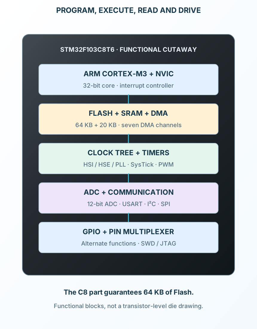
The Cortex-M3 core and DMA share memory and peripheral buses; GPIO selects which functions reach the pins.
72 MHzMaximum system clock
64 KBSpecified Flash
20 KBSRAM
−40–85 °CT6 temperature grade
Operating profile
STM32F103C8T6
Exact device and memory
Key parameters and their test conditions
- Core
- Arm Cortex-M3Conditions / notes: 32-bit; no hardware floating-point unit
- Maximum SYSCLK
- 72 MHzConditions / notes: Requires valid clock and Flash settings
- Flash
- 64 KBConditions / notes: C8 guarantee; do not rely on undocumented extra memory
- SRAM
- 20 KBConditions / notes: Application data and stack
- Package
- 48-lead LQFP, 7 × 7 mmConditions / notes: 0.5 mm lead pitch
- Temperature suffix 6
- −40 to +85°CConditions / notes: Selected C8T6
Package details
Follows the selected physical package
- Manufacturer
- STMicroelectronics
- Part number
- STM32F103C8T6
- Package
- LQFP-48
- Connections
- 48 pins
- Mounting
- SMD
- Lead pitch
- 0.5 mm
- Package code
- LQFP-48
- Thermal reference
- See manufacturer operating limits
Connections by function
Select a pin to open its function, electrical notes and wiring guidance.
Digital, analog and backup supplies9 pins
Digital GPIO and alternate functions17 pins
Oscillator connections4 pins
Reset and boot selection3 pins
ADC-capable GPIO10 pins
SWD / JTAG access5 pins
Power every domain
Connect VDD, VDDA, VBAT and all returns with local bypass.
Preserve debug access
Use SWDIO, SWCLK, reset, ground and a 3.3 V reference.
Choose clocks and modes
Configure buses, Flash latency and GPIO deliberately before increasing speed.
At HCLK = 8 MHz, SysTick clocked from HCLK with LOAD = 7999 gives a nominal 1 ms tick. Count 500 ticks for each LED toggle.
Pin reference
Select a pin to explore its function and connection.
48 pins
| Pin | Signal | Type | Function |
|---|---|---|---|
| VBAT | Supply | Supply connection for the named power domain. | |
| PC13 / TAMPER | Multiplexed pin | Multiplexed GPIO and the named default alternate function; remapping and peripheral configuration may change its use. | |
| PC14 / OSC32_IN | Multiplexed pin | GPIO multiplexed with the selected crystal oscillator function. | |
| PC15 / OSC32_OUT | Multiplexed pin | GPIO multiplexed with the selected crystal oscillator function. | |
| PD0 / OSC_IN | Multiplexed pin | GPIO multiplexed with the selected crystal oscillator function. | |
| PD1 / OSC_OUT | Multiplexed pin | GPIO multiplexed with the selected crystal oscillator function. | |
| NRST | Multiplexed pin | Active-low device reset. | |
| VSSA | Supply | Supply connection for the named power domain. | |
| VDDA | Supply | Supply connection for the named power domain. | |
| PA0 / WKUP | Multiplexed pin | Multiplexed GPIO and the named default alternate function; remapping and peripheral configuration may change its use. | |
| PA1 | Multiplexed pin | Multiplexed GPIO and the named default alternate function; remapping and peripheral configuration may change its use. | |
| PA2 / USART2_TX | Multiplexed pin | Multiplexed GPIO and the named default alternate function; remapping and peripheral configuration may change its use. | |
| PA3 / USART2_RX | Multiplexed pin | Multiplexed GPIO and the named default alternate function; remapping and peripheral configuration may change its use. | |
| PA4 / SPI1_NSS | Multiplexed pin | Multiplexed GPIO and the named default alternate function; remapping and peripheral configuration may change its use. | |
| PA5 / SPI1_SCK | Multiplexed pin | Multiplexed GPIO and the named default alternate function; remapping and peripheral configuration may change its use. | |
| PA6 / SPI1_MISO | Multiplexed pin | Multiplexed GPIO and the named default alternate function; remapping and peripheral configuration may change its use. | |
| PA7 / SPI1_MOSI | Multiplexed pin | Multiplexed GPIO and the named default alternate function; remapping and peripheral configuration may change its use. | |
| PB0 | Multiplexed pin | Multiplexed GPIO and the named default alternate function; remapping and peripheral configuration may change its use. | |
| PB1 | Multiplexed pin | Multiplexed GPIO and the named default alternate function; remapping and peripheral configuration may change its use. | |
| PB2 / BOOT1 | Multiplexed pin | Multiplexed GPIO and the named default alternate function; remapping and peripheral configuration may change its use. | |
| PB10 / I2C2_SCL | Multiplexed pin | Multiplexed GPIO and the named default alternate function; remapping and peripheral configuration may change its use. | |
| PB11 / I2C2_SDA | Multiplexed pin | Multiplexed GPIO and the named default alternate function; remapping and peripheral configuration may change its use. | |
| VSS1 | Supply | Supply connection for the named power domain. | |
| VDD1 | Supply | Supply connection for the named power domain. | |
| PB12 / SPI2_NSS | Multiplexed pin | Multiplexed GPIO and the named default alternate function; remapping and peripheral configuration may change its use. | |
| PB13 / SPI2_SCK | Multiplexed pin | Multiplexed GPIO and the named default alternate function; remapping and peripheral configuration may change its use. | |
| PB14 / SPI2_MISO | Multiplexed pin | Multiplexed GPIO and the named default alternate function; remapping and peripheral configuration may change its use. | |
| PB15 / SPI2_MOSI | Multiplexed pin | Multiplexed GPIO and the named default alternate function; remapping and peripheral configuration may change its use. | |
| PA8 / MCO | Multiplexed pin | Multiplexed GPIO and the named default alternate function; remapping and peripheral configuration may change its use. | |
| PA9 / USART1_TX | Multiplexed pin | Multiplexed GPIO and the named default alternate function; remapping and peripheral configuration may change its use. | |
| PA10 / USART1_RX | Multiplexed pin | Multiplexed GPIO and the named default alternate function; remapping and peripheral configuration may change its use. | |
| PA11 / USB_DM | Multiplexed pin | Multiplexed GPIO and the named default alternate function; remapping and peripheral configuration may change its use. | |
| PA12 / USB_DP | Multiplexed pin | Multiplexed GPIO and the named default alternate function; remapping and peripheral configuration may change its use. | |
| PA13 / SWDIO | Debug / GPIO | Debug port function at reset; some pins can be released to GPIO with software configuration. | |
| VSS2 | Supply | Supply connection for the named power domain. | |
| VDD2 | Supply | Supply connection for the named power domain. | |
| PA14 / SWCLK | Debug / GPIO | Debug port function at reset; some pins can be released to GPIO with software configuration. | |
| PA15 / JTDI | Debug / GPIO | Debug port function at reset; some pins can be released to GPIO with software configuration. | |
| PB3 / JTDO | Debug / GPIO | Debug port function at reset; some pins can be released to GPIO with software configuration. | |
| PB4 / NJTRST | Debug / GPIO | Debug port function at reset; some pins can be released to GPIO with software configuration. | |
| PB5 | Multiplexed pin | Multiplexed GPIO and the named default alternate function; remapping and peripheral configuration may change its use. | |
| PB6 / I2C1_SCL | Multiplexed pin | Multiplexed GPIO and the named default alternate function; remapping and peripheral configuration may change its use. | |
| PB7 / I2C1_SDA | Multiplexed pin | Multiplexed GPIO and the named default alternate function; remapping and peripheral configuration may change its use. | |
| BOOT0 | Multiplexed pin | Boot-mode selection sampled at reset. | |
| PB8 | Multiplexed pin | Multiplexed GPIO and the named default alternate function; remapping and peripheral configuration may change its use. | |
| PB9 | Multiplexed pin | Multiplexed GPIO and the named default alternate function; remapping and peripheral configuration may change its use. | |
| VSS3 | Supply | Supply connection for the named power domain. | |
| VDD3 | Supply | Supply connection for the named power domain. |
No pins match. Try a signal name or choose All pins.
Exact device and memory
Do not substitute larger family members
Manufacturer specifications 7 parameters
| Parameter | Value | Conditions / notes |
|---|---|---|
| Core | Arm Cortex-M3 | 32-bit; no hardware floating-point unit |
| Maximum SYSCLK | 72 MHz | Requires valid clock and Flash settings |
| Flash | 64 KB | C8 guarantee; do not rely on undocumented extra memory |
| SRAM | 20 KB | Application data and stack |
| Package | 48-lead LQFP, 7 × 7 mm | 0.5 mm lead pitch |
| Temperature suffix 6 | −40 to +85°C | Selected C8T6 |
| GPIO | Up to 37 I/O | Some consumed by clocks, debug or peripherals |
No specifications match. Try a parameter name or a unit.
The device name describes memory, pin count, package and temperature grade.
Power-domain connections
3.3 V reference circuit
Manufacturer specifications 7 parameters
| Parameter | Value | Conditions / notes |
|---|---|---|
| VDD1 / VDD2 / VDD3 | Pins 24 / 36 / 48 | 3.3 V; 100 nF near each pair plus local bulk |
| VSS1 / VSS2 / VSS3 | Pins 23 / 35 / 47 | Common ground |
| VDDA / VSSA | Pins 9 / 8 | Analog rail and return; 1 µF + 10 nF bypass |
| VBAT | Pin 1 | Tie to VDD when no separate backup supply is used |
| Digital VDD | 2.0–3.6 V | Recommended range |
| ADC VDDA | 2.4–3.6 V | Specified ADC operating range |
| Input tolerance | Pin and mode dependent | Do not feed 5 V into an analog input |
No specifications match. Try a parameter name or a unit.
All supply contacts are required even for a minimal program.
Clock tree and bus limits
Firmware controls the operating speed
Manufacturer specifications 8 parameters
| Parameter | Value | Conditions / notes |
|---|---|---|
| Reset system clock | Internal HSI, nominal 8 MHz | Used by this example |
| External HSE crystal | 4–16 MHz | Select load capacitors for the crystal |
| HSI PLL input | HSI divided by 2 | PLL multiplier limits still apply |
| SYSCLK / AHB | Up to 72 MHz | Match Flash latency and supply conditions |
| APB1 | Up to 36 MHz | Use a divider at 72 MHz SYSCLK |
| APB2 | Up to 72 MHz | Independent peripheral enables |
| ADC clock | Up to 14 MHz | Select ADC prescaler and sampling time |
| USB clock | 48 MHz with specified accuracy | Reset HSI-only example is not a USB design |
No specifications match. Try a parameter name or a unit.
A 72 MHz target constant does not configure the hardware clock tree.
Boot and programming
Keep a recoverable SWD path
Manufacturer specifications 7 parameters
| Parameter | Value | Conditions / notes |
|---|---|---|
| Normal Flash boot | BOOT0 low | 10 kΩ pull-down on pin 44 |
| System memory | BOOT0 high, BOOT1 low | Built-in serial bootloader; check ST bootloader documentation |
| SRAM boot | BOOT0 high, BOOT1 high | Special development use |
| BOOT1 | PB2 pin 20 | Defined low in the reference |
| SWDIO / SWCLK | PA13 pin 34 / PA14 pin 37 | 3.3 V-compatible programmer |
| NRST | Pin 7 | Expose reset to programmer; optional button |
| JTAG pins | PA15 / PB3 / PB4 also reserved initially | Disable JTAG while retaining SWD if these GPIO are needed |
No specifications match. Try a parameter name or a unit.
Do not enable readout protection or remove debug access casually.
Common interface assignments
Default mappings; selected remaps exist
Manufacturer specifications 8 parameters
| Parameter | Value | Conditions / notes |
|---|---|---|
| USART1 TX / RX | PA9-30 / PA10-31 | Logic levels, not RS-232 voltage |
| USART2 TX / RX | PA2-12 / PA3-13 | Shared with ADC inputs |
| I²C1 SCL / SDA | PB6-42 / PB7-43 | External pull-ups to a compatible rail |
| I²C2 SCL / SDA | PB10-21 / PB11-22 | Open-drain bus configuration |
| SPI1 NSS / SCK / MISO / MOSI | PA4-14 / PA5-15 / PA6-16 / PA7-17 | Shared analog-capable pins |
| SPI2 NSS / SCK / MISO / MOSI | PB12-25 / PB13-26 / PB14-27 / PB15-28 | Configure chip select deliberately |
| USB DM / DP | PA11-32 / PA12-33 | External interface and accurate clock required |
| CAN | Shared resources with USB | External CAN transceiver required |
No specifications match. Try a parameter name or a unit.
The peripheral block does not supply external bus transceivers or pull-ups.
ADC and restricted GPIO
48-pin device details
Manufacturer specifications 7 parameters
| Parameter | Value | Conditions / notes |
|---|---|---|
| External ADC channels | PA0–PA7 and PB0–PB1 | Ten externally available inputs |
| ADC resolution | 12-bit | Sampling time and source impedance affect accuracy |
| Reference | VDDA / VSSA on this package | No separate external VREF pins |
| Calibration | Run after power-up | Follow ADC initialization sequence |
| PC13–PC15 | Restricted output drive | Do not source LED current from these pins |
| LED example | PA0 pin 10 | General push-pull output in this circuit |
| Analog input span | VSSA through VDDA | No 5 V tolerance in analog mode |
No specifications match. Try a parameter name or a unit.
The internal temperature sensor measures die temperature, not a guaranteed ambient temperature.
HSI LED starting circuit
No external oscillator required
Manufacturer specifications 7 parameters
| Parameter | Value | Conditions / notes |
|---|---|---|
| Supply | 3.3 V to all required rails | Local decoupling and a bulk capacitor |
| BOOT0 / BOOT1 | Defined low | Boot from programmed Flash |
| Output | PA0-10 → 1 kΩ → red LED → GND | Ideal current about 1.3 mA for a 2 V LED |
| GPIO setup | Enable GPIOA clock; set PA0 output | Choose low output speed and known initial state |
| SysTick clock | HCLK = 8 MHz | Select core clock as SysTick source |
| SysTick reload | 7999 | (7999 + 1) / 8 MHz = 1 ms |
| Blink | Toggle every 500 ticks | Nominal full cycle 1 second |
No specifications match. Try a parameter name or a unit.
Actual RC oscillator tolerance affects timing; the illustration is not firmware execution.
Embedded controllers
Timers, interrupts and serial links.
Manufacturer application guideData acquisition
ADC with DMA and deliberate sampling.
Manufacturer application guideCommunication endpoints
Add the required external interface hardware.
Manufacturer application guideTake it into ProTech
Find STM32F103C8T6 in the Components Library to place its schematic symbol and connect its pins.
Reference page · circuit simulation model not yet availableOpen ProTech