Hello friends! In this tutorial, we will learn how to program a PIC microcontroller with code compiled in mikroC PRO for PIC, using a PICkit 3 programmer. The useful idea is simple: mikroC builds the firmware, and Microchip's programming software loads the resulting HEX file into the selected device.
The original project behind this lesson required mikroC, while the available programmer was a USB-connected PICkit 3. Moving from a serial-port programmer to PICkit 3 made the laptop connection easier, but the compiler and programmer still needed a common file format. The HEX file provides that connection without requiring us to compile the project again in another C compiler.
We will preserve the original MPLAB IDE screenshot sequence, explain what each step does, and cover the important checks for target power, device selection and configuration bits. We will also distinguish the old MPLAB interface from MPLAB X and IPE so that you do not search for menus that belong to a different application.

Understand the Compiler and Programmer Workflow
mikroC translates your source code and linked libraries into instructions for the selected PIC device. The programmer does not normally need the original C source to write those instructions into program memory. It needs the programming image, the correct device definition and a working electrical connection to the target.
| Part | Responsibility | What you should check |
|---|---|---|
| mikroC project | Builds the firmware image. | Exact device, clock setting, libraries and configuration options. |
| HEX file | Carries addressed programming data. | Build success, correct path and recent modification time. |
| MPLAB programming software | Loads the image and controls the programmer. | Device support, selected tool and programming options. |
| PICkit 3 | Communicates with the target's programming interface. | USB connection, target voltage and ICSP wiring. |
| Target board | Runs the programmed application. | Power, reset, oscillator and application connections. |
This explains why the original requirement for the C18 compiler was unnecessary for the transfer itself. If mikroC has already produced a valid image, a second compiler is not required merely to import and program it. A project that needs source-level debugging is a separate case with additional format and toolchain requirements.
Choose a Compatible MPLAB Version
The screenshots in this article show the legacy MPLAB IDE interface with Configure and Programmer menus. MPLAB X IDE and MPLAB IPE have different interfaces. IPE is intended for programming operations, whereas an IDE also provides project development and debugging features.
Version compatibility matters for this older programmer. Microchip states that MPLAB X IDE 6.25 discontinued support for PICkit 3; the earlier supported releases extend through version 6.20. Do not install the newest MPLAB X release and assume it must support every previous programmer.
Use Microchip's official download archive when maintaining a compatible legacy setup, and check that the chosen software supports your exact PIC device as well as the tool. For a new development environment, evaluate currently supported programmers instead of making an archived installation the long-term foundation.
The old screenshots remain useful for understanding the original sequence. They are not screenshots of a current installer, and their menu positions should not be treated as instructions for every release.
Gather the Required Hardware and Software
- A working PICkit 3 and a USB data cable.
- A supported PIC microcontroller on a suitable target board or programming adapter.
- Access to the target's programming connections.
- A mikroC PRO for PIC installation able to build the project within its licence and device support.
- Compatible Microchip programming software.
- The target device's data sheet and programming information.
A full mikroC licence is not an electrical requirement for PICkit 3. The important point is whether your compiler installation can legally and successfully build the project you are using. Obtain software and documentation from their publishers; a newsletter subscription is not a software licence or a replacement for an official installer.
Before changing any wiring, disconnect power. Confirm the device marking and package rather than identifying a chip only by the number of pins. Similar-looking PIC parts can have different memory maps, configuration fields and programming requirements.
Connect the PICkit 3 to the Target
The PICkit 3 header uses programming signal names, not universal PIC package pin numbers. Trace each signal to the matching pin of your selected microcontroller. Microchip's PICkit 3 User's Guide documents the connector and target-connection requirements.
| PICkit 3 header pin | Signal | Target connection |
|---|---|---|
| 1 | MCLR/VPP | The target programming-voltage/reset connection. |
| 2 | VDD | Target supply sensing, or tool-supplied power when deliberately enabled. |
| 3 | VSS/GND | Target ground. |
| 4 | PGD/ICSPDAT | The selected device's programming data pin. |
| 5 | PGC/ICSPCLK | The selected device's programming clock pin. |
| 6 | PGM/LVP or auxiliary function | Use only as required by the device and programming mode. |
Align pin 1 using the programmer's marking and the adapter documentation. Reversing a connector can apply the wrong signal to the supply or reset circuit. A six-wire cable is not proof that its orientation is correct.
For a first setup, keep the connection short and simple. Application circuitry attached to clock, data or reset can interfere with programming. Check the device and tool guidance before adding large capacitors, strong pull resistors or other loads to those signals.
The target needs its normal supply connections, including all required supply and ground pins. A programming connector does not repair an incomplete power circuit. Verify the board's connections and decoupling against the device documentation before assuming a software problem.
Step 1: Build the Firmware in mikroC
- Open the correct mikroC project.
- Confirm the exact target device in the project settings.
- Set the oscillator frequency expected by the project's delay and timing calculations.
- Review configuration options such as oscillator mode, watchdog and reset behavior for that device.
- Save your source files and run Project, Build.
- Read the build result and locate the generated HEX file.
The mikroC Build reference describes the build command. Check the output location for your project rather than importing the first similarly named file you find. The original tutorial used the HEX file produced alongside its project files.
A failed build can leave an older HEX file in the output folder. Its presence alone does not prove that your latest source compiled. Confirm a successful build and check the image's timestamp before loading it into MPLAB.
The compiler frequency setting and physical oscillator arrangement must agree. A successful programming operation cannot correct code generated with the wrong timing assumptions. Keep a short note of the device, clock and build configuration with each image you use on hardware.
Step 2: Select the Device in Legacy MPLAB
Open the compatible legacy MPLAB IDE. If an unrelated workspace is open, close it so that its settings do not confuse the programming exercise. Choose Configure, Select Device, and select the same device used by the mikroC project.
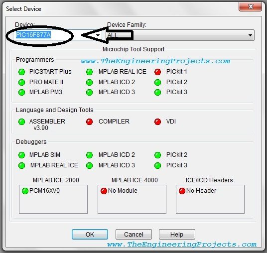
Match the complete part name, including meaningful suffixes where the software distinguishes them. Selecting a vaguely similar member of the same family is not an acceptable substitute. Device selection tells the programming software how to interpret addresses and configuration data.
Next, open the Configuration Bits view. The original workflow uses the option labelled Configuration Bits set in code so that the imported image supplies its configuration values.
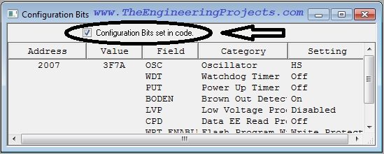
For an externally built project, “set in code” means using the configuration information included in that programming image. It does not mean MPLAB is recompiling the mikroC source. Inspect the imported configuration data and ensure it matches the target board.
Do not assume every HEX file includes every region you intend to program. Application code, configuration words and data EEPROM can be handled differently depending on the build and device. Review those regions and the programming tool's include, preserve or erase settings before proceeding.
Step 3: Select PICkit 3 and Set Target Power
Connect the programmer through its USB cable. In legacy MPLAB, use Programmer, Select Programmer, PICkit 3. The output pane should report the connection process. A tool-firmware operation may be required by a supported setup; follow the software's instructions and do not disconnect it during an active update.
The original screenshot below shows a target-power problem during connection. Read the actual text in your output pane because a missing target voltage, a USB failure and a device-identification failure have different causes.
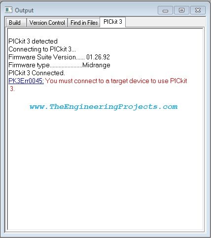
When the Board Has Its Own Supply
Keep programmer-supplied target power disabled when the board is already powered by its intended supply. Connect the programmer's ground and voltage-sense connection correctly. Confirm the voltage at the target, not just at an unloaded power adapter.
For mixed-voltage boards, identify the supply and programming voltage requirements of the microcontroller itself. Do not choose a voltage solely because another module on the board uses it.
When the Programmer Supplies the Target
For a suitably small target circuit, the tool may supply power when that option is supported and its limits are respected. In the original interface, open Programmer, Settings, Power and select Power target circuit from PICkit 3. Set a voltage appropriate to the target.
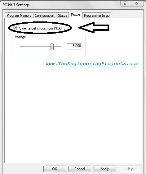
Calculate the whole target load before using programmer power. As an illustrative budget, a controller drawing 12 mA, two indicators drawing 3 mA each and another circuit drawing 15 mA total 33 mA. Compare the actual worst-case load, including startup demand, with the documented tool limit. The arithmetic is useful even when your particular board uses different values.
A relay, motor, radio burst or heavily loaded peripheral can make the target unsuitable for programmer power. Do not enable the option simply because it removes a warning. Choose one intended power arrangement and avoid connecting two supplies in opposition.
After correcting the supply configuration, reconnect through the programming interface and inspect the detected target information.
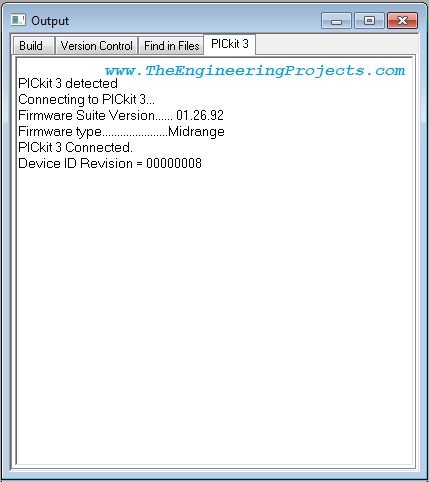
If identification still fails, check the physical connection before repeatedly changing software settings. Measure the target voltage, confirm header orientation and verify the clock and data wiring against the exact device.
Step 4: Import the HEX File and Program
In the legacy workflow, choose File, Import and select the HEX file produced by the successful mikroC build. Read the output pane to confirm that the intended file was loaded. Inspect the program and configuration information before starting the write.
- Confirm the selected device and programmer.
- Confirm the target supply arrangement.
- Load the exact HEX file you just built.
- Review configuration and any preserved memory regions.
- Choose Programmer, Program.
- Wait for the operation and verification result.
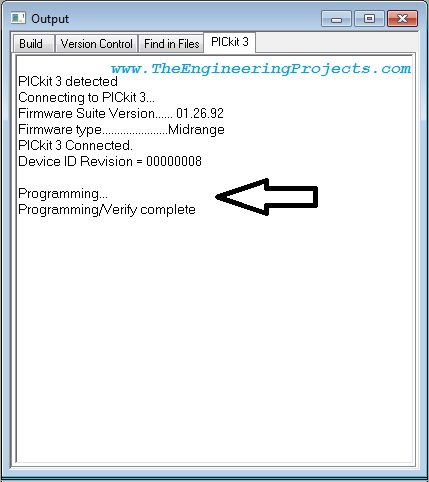
Programming normally overwrites the selected target memory. If the board contains settings, calibration data or firmware you need to preserve, decide how to handle those regions before starting. A programming tutorial should not assume that every connected board is a blank development device.
The original article advised always connecting before importing. That is a useful order for reproducing its session, but not a universal rule of the HEX format. Different supported tools can load files at different stages. The real requirement is that the correct file, device and settings are active when programming begins.
Using the Same Idea in MPLAB IPE
For a compatible IPE release, the essential process is similar: select the supported device, select PICkit 3, connect the target, browse to the built HEX file and program it. Power settings and advanced options appear in different places from the legacy screenshots.
Consult the IPE documentation included with your installed version. Do not translate a legacy menu sequence into an assumed modern menu path. You also do not need to create a new C project merely to program an already built application image.
If the tool does not appear for the chosen device, check both software-version support and device support. Reinstalling mikroC will not make an unsupported programmer available inside another application.
Verify Programming and Then Check Application Behavior
A successful verify result indicates agreement for the memory regions the programming operation checked. It does not prove that the application's clock, wiring or program logic is correct. Release the target from reset as required by the tool and observe a simple expected behavior.
A blinking indicator is a useful first check because its state and timing are easy to inspect. Our PIC16F877A LED-blinking tutorial is a separate device-specific example; use its wiring and configuration only when that is actually your target.
If a delay-based program assumes an 8 MHz clock while the board effectively runs at 4 MHz, the timing may be approximately twice as slow, subject to the device's clock arrangement and generated code. That kind of mismatch can exist even after a completely successful flash write.
When the application fails, first distinguish “cannot communicate with the PIC” from “programmed PIC does not behave as expected.” The first points toward programming connections, power or support. The second also requires examination of reset, oscillator selection, pin configuration and the application circuit.
Troubleshooting Table
| Symptom | Checks to make |
|---|---|
| PICkit 3 is absent from the tool list. | Supported MPLAB release, USB connection and tool availability for the selected device. |
| Target voltage is missing. | Target supply, common ground, VDD connection and chosen power source. |
| Device identification is wrong or unavailable. | Exact part selection, header orientation and programming signal connections. |
| Programming or verification fails. | Supply stability, interference on programming pins and memory/protection settings. |
| The old program still appears to run. | Build success, HEX path, timestamp and which physical target was programmed. |
| The new program runs at the wrong speed. | Compiler clock value, oscillator configuration and actual clock source. |
| The program verifies but no output changes. | Reset state, watchdog behavior, pin direction, analog mode and external wiring. |
Keep the Rebuild and Programming Cycle Reliable
After changing the source, build again and reload the new image. Do not assume the programming application's memory buffer automatically tracks every change to a file on disk. Use its documented reload behavior or explicitly import the newly built file.
For each important hardware trial, record the source revision, compiler version, selected device, clock, configuration settings and HEX filename. If you keep several builds, give them unambiguous names or separate folders. This prevents a successful programming message from hiding the fact that you loaded the wrong experiment.
Change one uncertain part at a time. For example, establish reliable device identification before troubleshooting application timing. A repeatable sequence makes the original two-tool workflow quite straightforward: build in mikroC, load the resulting image, program and inspect the target behavior.
Frequently Asked Questions
Do I need the C18 compiler to program a mikroC HEX file?
No. The image is already compiled. You need compatible programming software and device support, not a second compiler for this import-and-program operation.
Can PICkit 3 directly understand my C source?
No. Build the project into a supported programming image first. Source-level debugging additionally depends on the compiler's debug information and the debugger's supported formats.
Should I always power the board from PICkit 3?
No. Choose the supply arrangement according to the board's voltage and current requirements and the tool's limits. An externally powered target still needs the correct ground and sense connections.
Can I use the latest MPLAB X with PICkit 3?
Do not assume compatibility. Microchip ended its support in MPLAB X IDE starting with 6.25. Use a compatible archived environment for this legacy tool or move to supported hardware and software.
Why must the device match in both applications?
The compiler generates instructions and configuration data for a particular target, while the programming application interprets the image using a device definition. A mismatch invalidates that agreement.
Does verification prove that my complete project works?
No. It checks the programmed data within the operation's scope. You must still evaluate power, reset, clock, input/output behavior and the actual application requirements.