Hello friends, I hope you all are doing great. Today, I am going to share the new ADXL345 Accelerometer Library for Proteus V1.0. The ADXL345 is the small 3-axis accelerometer on the purple GY-291 module that you find in tilt sensors, step counters, drop detectors and self-balancing robots. It does more than measure: the chip itself can catch a tap, a double tap, the start and the end of a movement and a free fall, and tell the Arduino on an interrupt pin. Now you can build and test those projects in Proteus.
Behind the part sits our own model, not a part that shows a number. The ADXL345 answers the Arduino exactly as its datasheet says: its registers on I2C, the data rate, the four ranges with full resolution or 10 bits, and the tap, activity, inactivity and free-fall functions on its INT1 and INT2 pins. You tilt the board and knock on it from a panel. You get two devices: a Simple device with a live STATUS panel and the board's controls, and an Advance device with a pop-up window and the test tools. The demo runs the Adafruit ADXL345 library on our Arduino UNO V4.0.
NOTICE: an accelerometer is easy to fake: hand the Arduino three numbers from a property. We wanted more. Our ADXL345 samples at its data rate, keeps its registers, clips at its range and runs the tap detector on the whole knock, so the Adafruit library reads it exactly as on your desk, and a missed tap or a wrong scale fails exactly as it does there. It took our team a lot of hard work. Your feedback is the fuel that keeps us going, so please tell us what you think in the comments below or in the ADXL345 board of our forum. And if our free libraries help you, you can buy us a coffee. So, let's get started with the ADXL345 Accelerometer Library for Proteus V1.0:
What is the ADXL345?
The ADXL345 from Analog Devices is a 3-axis digital accelerometer in a 3 x 5 mm package. It measures the acceleration along X, Y and Z, up to plus or minus 16 g, and sends it over I2C or SPI. At rest it feels gravity, so the three values tell you how the board is tilted. Read more in our ADXL345 3-Axis Digital Accelerometer article. If you also need a gyroscope, look at the MPU6050 in our Introduction to MPU6050 and our MPU6050 Library for Proteus; another small accelerometer is the LIS3DH Triple-Axis Accelerometer. The GY-291 module adds a 3.3 V regulator and the I2C pull-ups, so it works from 5 V too.
| ADXL345 | |
|---|---|
| Ranges | +-2, +-4, +-8 and +-16 g |
| Resolution | full resolution: 3.9 mg a count (256 counts a g) at every range; or 10 bits |
| Data rate | 0.10 to 3200 Hz (100 Hz after power-on) |
| Functions | single tap, double tap, activity, inactivity, free fall on INT1 / INT2 |
| Interface | I2C at 0x53 (SDO low) or 0x1D (SDO high); SPI with CS low |
| Supply | 2.0 to 3.6 V (the GY-291 module: 3.3 or 5 V) |
| Devices | ADXL345TEP (Simple) and ADXL345ADVTEP (Advance) |
Registers, Range and Resolution
The ADXL345 has registers: DEVID at 0x00 always reads 0xE5; POWER_CTL at 0x2D starts the measurement with its Measure bit (0x08); BW_RATE sets the data rate and DATA_FORMAT the range. The six data registers from 0x32 hold X, Y and Z, each as two bytes, low byte first. In full resolution one count is 3.9 mg at every range, so 1 g is 256 counts and only the limit grows with the range; in 10-bit mode the step grows instead.
The Functions and the INT Pins
A tap lasts a few milliseconds, too short for a sketch that reads the data twice a second. So the chip watches the acceleration itself. INT_ENABLE turns the functions on, INT_MAP sends each one to INT1 or INT2, and INT_SOURCE at 0x30 says what happened. The pin stays HIGH until the sketch reads INT_SOURCE, which clears the events. The thresholds and times have their own registers: THRESH_TAP, DUR, Latent and Window for the taps, THRESH_ACT, THRESH_INACT and TIME_INACT for movement, THRESH_FF and TIME_FF for a free fall.
What's New in ADXL345 Accelerometer Library for Proteus V1.0
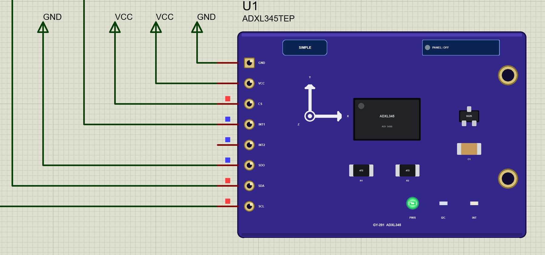
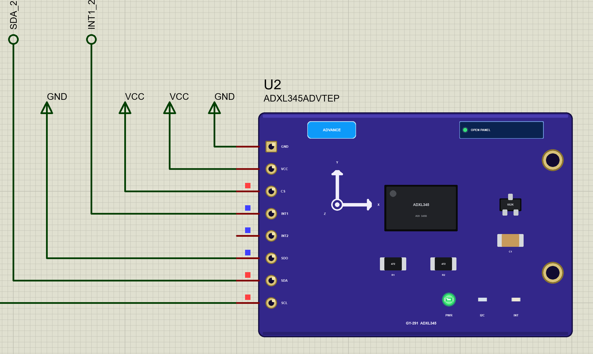
- The real module: the purple GY-291 with the ADXL345, its regulator, the pull-ups and the X / Y / Z marks, drawn at about three times its real size, with the header GND, VCC, CS, INT1, INT2, SDO, SDA and SCL.
- Two styles: a Simple device with a STATUS panel and an Advance device with a pop-up window; the PWR, I2C and INT LEDs and the panel button sit on the board itself.
- The real ADXL345: the registers, standby and Measure, the data rate, the four ranges, full resolution and 10 bits, the offsets and the noise, the address pin and SPI mode on CS.
- The chip's own functions: single tap, double tap, activity, inactivity with the link bit, and free fall, on INT1 and INT2, active high or low.
- The board on the panel: pitch and roll, six orientations from FLAT to UPSIDE DOWN, and four motions: TAP, DOUBLE TAP, SHAKE and FREE FALL.
- Mistake detection: data read in standby, CS low, X and Z from two different samples, a reading beyond the range, a write to a read-only register.
- Four test tools on the Advance device: I2C, Readings, Interrupts and taps, and Range and resolution.
- A two-node demo on our Arduino UNO V4.0 with the Adafruit library and INT1 on D2.
- A compact package: about 1.32 MB, without the C++ source code of the model.
Two Devices: Simple and Advance
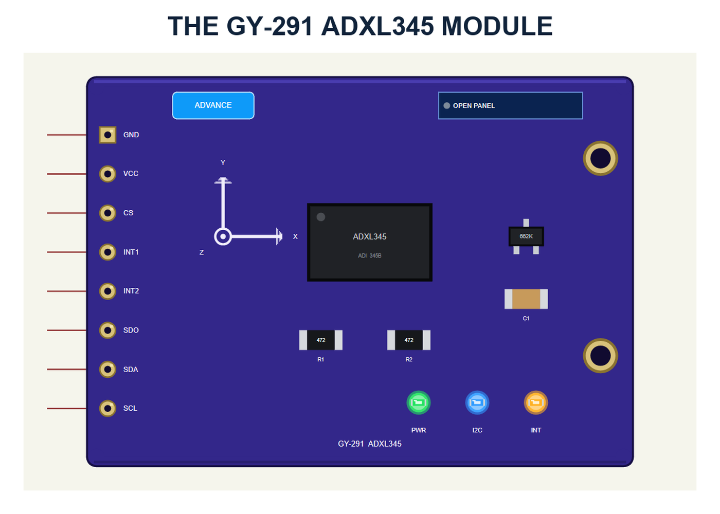
The module carries the ADXL345 in the middle, the 662K regulator, the 4.7 kohm pull-ups R1 and R2, the capacitor C1 and the axis marks: X to the right, Y up, Z out of the board. The header on the left has all eight pins of the real GY-291.
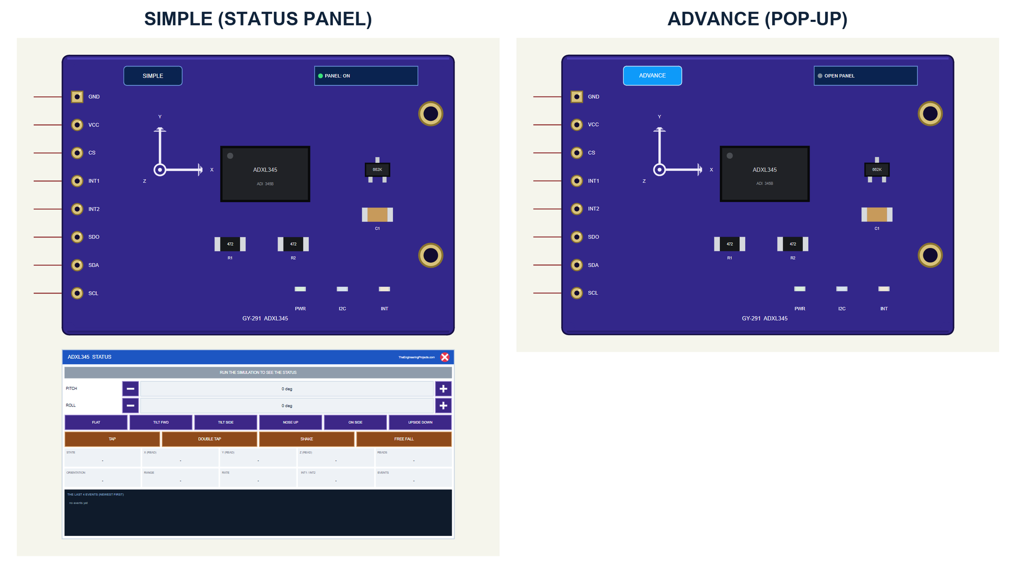
| Simple | Advance | |
|---|---|---|
| Device | ADXL345TEP | ADXL345ADVTEP |
| On the schematic | The module and the STATUS panel | The module |
| The board's tilt and motions | On the STATUS panel | In the pop-up |
| Status | Banner, 10 readouts, the last 4 events | A pop-up: Sensor, Event log, Tests |
Download ADXL345 Accelerometer Library for Proteus
Click the button below to download ADXL345-Accelerometer-Library-for-Proteus-v1.0.zip (about 1.32 MB, without the C++ source code of the model):
ADXL345 Accelerometer Library for Proteus V1.0: GY-291, Tap, Free Fall- README.txt: the devices, installation, the demo, wiring, the test tools and real hardware.
- Proteus Library Files:
TEPADXL345.LIBandArduinoV4TEP.LIBfrom our Arduino Library for Proteus V4.0. - Proteus Model Files:
TEPADXL345.DLLandTEPARDUINO.DLL. - Proteus Simulation:
ADXL345-Accelerometer-ArduinoUnoV4.pdsprj,ADXL345_Demo.hexand copies of the two DLLs. - Arduino Code:
ADXL345_Demo.ino. It needs the Adafruit ADXL345 library from the Library Manager of the Arduino IDE, only if you want to change the sketch.
No Proteus yet? Read How to Download and Install Proteus 7 and 8. New to libraries? Follow How to Install a New Library in Proteus.
How to Install ADXL345 Accelerometer Library for Proteus
- Close Proteus and extract the whole zip file, for example to your Desktop.
- Copy the two files from Proteus Library Files into the LIBRARY folder of Proteus (usually
C:\Program Files (x86)\Labcenter Electronics\Proteus 8 Professional\LIBRARY). - Copy
TEPADXL345.DLLandTEPARDUINO.DLLfrom Proteus Model Files into the MODELS folder. - Delete
TEPADXL345.IDXfrom the LIBRARY folder if it is there. - Start Proteus, press P and search for ADXL345.
Tip: keep the Proteus Simulation folder together, because the project needs its .hex file and the DLLs beside it. The library is tested in Proteus 8.5; Proteus 7 is not supported.
The ADXL345 Parts in Proteus
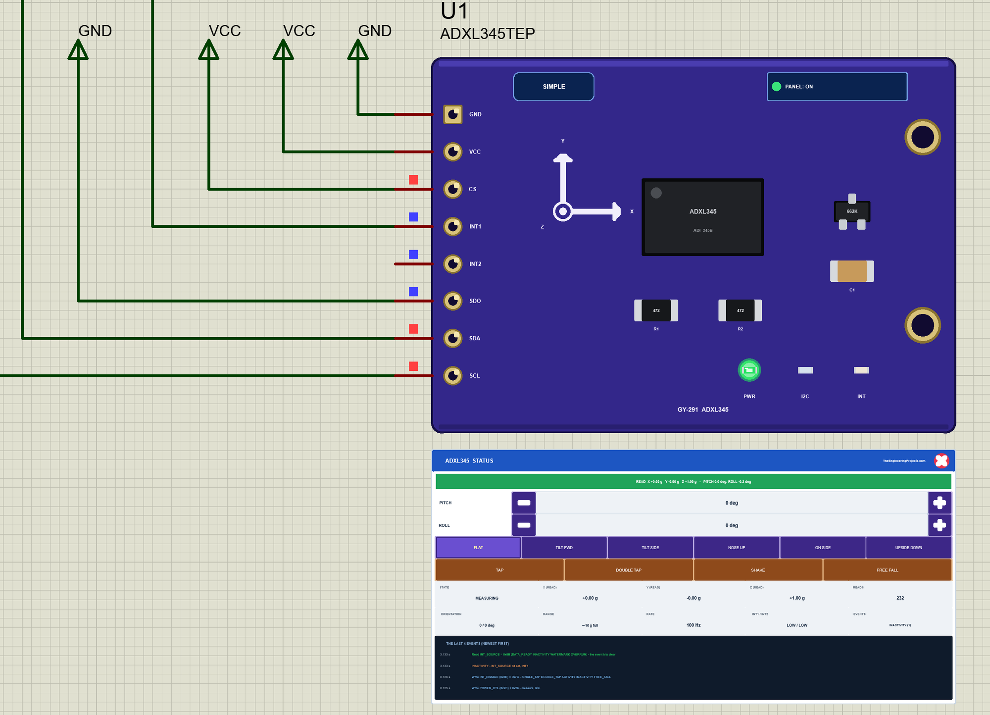
Three LEDs sit on the module's board: PWR while VCC is there, I2C, which flashes when the Arduino talks to the module, and INT, which lights when the chip raises an interrupt. Next to the SIMPLE or ADVANCE badge is the panel button. The LEDs, the badge, the button and the panels are TEP additions; the real module has none of them.
The Simple device adds the STATUS panel. Its banner shows what the sketch read, turns amber for a tap, a fall or another event, and red for a warning. Below it are the board's controls: PITCH and ROLL with - and + (5 degrees a click), six orientations (FLAT, TILT FWD, TILT SIDE, NOSE UP, ON SIDE and UPSIDE DOWN) and four motions (TAP, DOUBLE TAP, SHAKE and FREE FALL). Ten readouts follow - the state, X, Y and Z as read, the reads, the orientation, the range, the data rate, the two INT pins and the last event - and the last four events.
The red X closes the STATUS panel, and the PANEL button on the board opens it again:
The Advance device keeps the schematic clean: only the module. Its live data opens in a pop-up window at Run, and the OPEN PANEL button on the board brings the window back. The properties PITCH and ROLL set the board's tilt at the start; NOISE (1 by default, about one count) sets the chip's noise.
The Demo Circuit
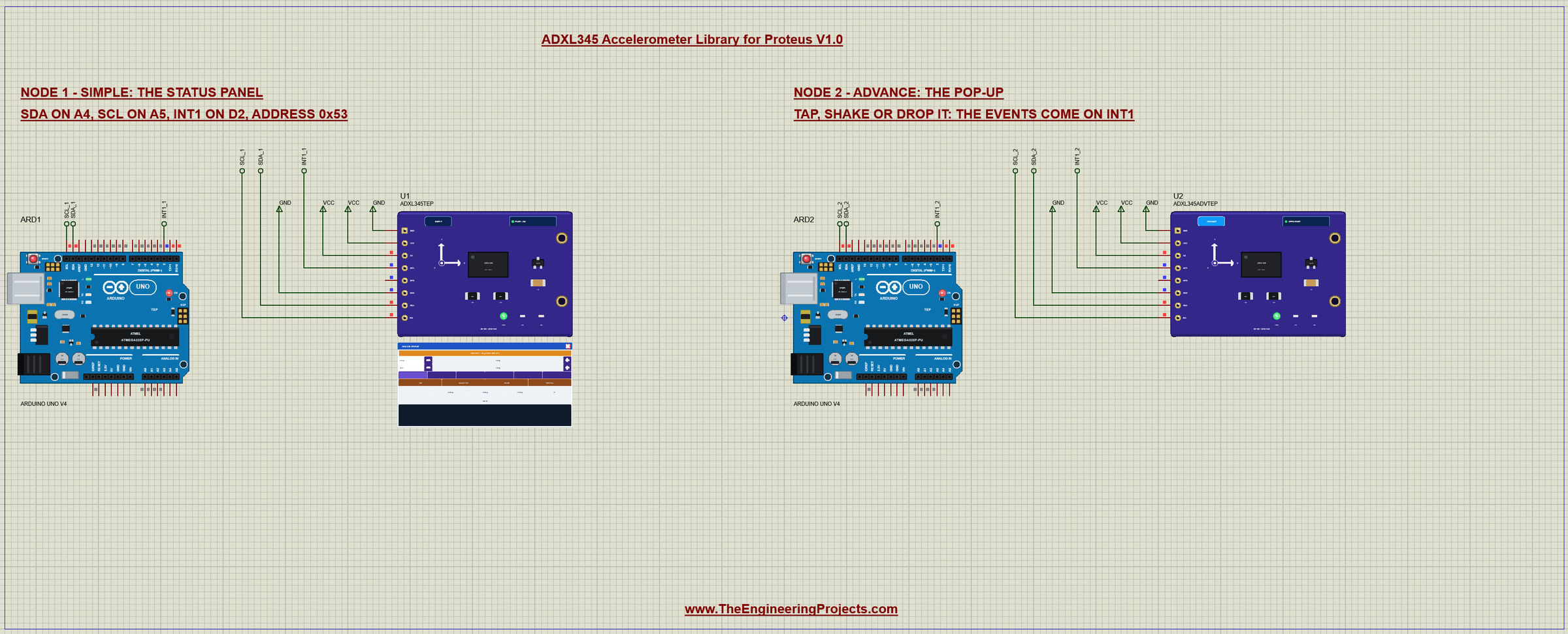
The demo project has two nodes. Each one is an Arduino UNO V4.0 from our Arduino UNO Library for Proteus V4.0 with a GY-291 on its SDA and SCL pins, which are A4 and A5, and INT1 on D2, the UNO's INT0. CS goes to VCC for I2C and SDO to GND for the address 0x53. Both UNOs run the same ADXL345_Demo.hex, and both boards start flat.
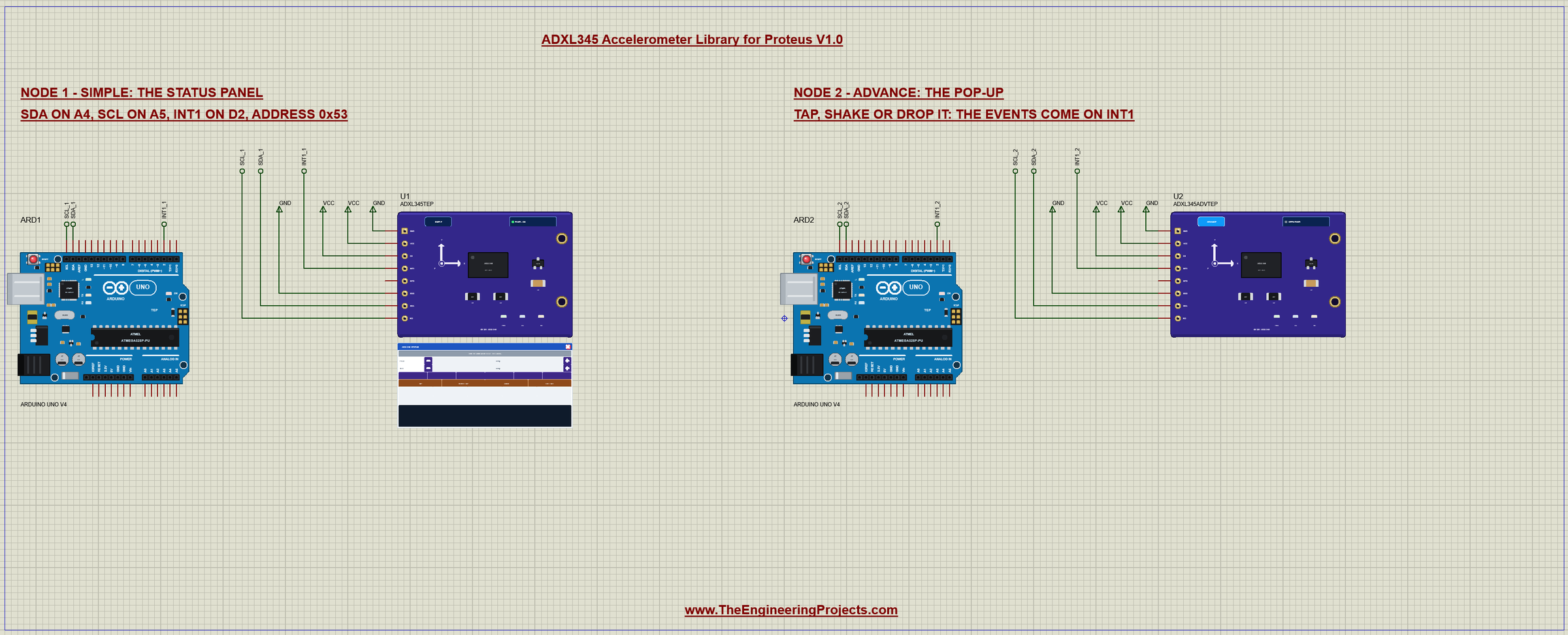
Wiring
| Module | Arduino UNO |
|---|---|
| VCC | 5V (the regulator gives the chip 3.3 V) |
| GND | GND |
| CS | VCC (high = I2C) |
| SDO | GND (address 0x53; VCC = 0x1D) |
| INT1 | D2 (INT0) |
| INT2 | open |
| SCL | A5 (the SCL pin) |
| SDA | A4 (the SDA pin) |
In Proteus, SDA, SCL and INT1 reach their UNO through net labels, SDA_1, SCL_1 and INT1_1 for node 1 and the same with _2 for node 2. The Wire library turns on the UNO's internal pull-ups, which hold the I2C bus HIGH in the simulation. The serial monitor needs no wires at all, because it is built into the UNO V4.0.
The Arduino Code
The demo sketch uses the Adafruit ADXL345 library (version 1.3.4) with Adafruit Unified Sensor and Adafruit BusIO. New to Arduino? Start with Arduino Tutorial for Beginners and Introduction to Arduino UNO. The sketch begins with Wire and the two Adafruit headers:
#include <Wire.h>
#include <Adafruit_Sensor.h>
#include <Adafruit_ADXL345_U.h>
In setup(), accel.begin() looks for the chip at 0x53, checks DEVID 0xE5 and sets the Measure bit. The sketch then picks plus or minus 16 g, which the library always sets with full resolution, and 100 Hz:
  found = accel.begin(ADXL_ADDR);
  if (!found) { Serial.println(F("ADXL345 not found - check the wiring (CS to VCC, SDO to GND)")); return; }
  Serial.println(F("ADXL345 found at 0x53 (DEVID 0xE5)"));
  accel.setRange(ADXL345_RANGE_16_G);
  accel.setDataRate(ADXL345_DATARATE_100_HZ);
  setupFunctions();
The library has no functions for the taps and the other events, but its writeRegister() is public, so the sketch sets them with the datasheet's starting values. The link bit in POWER_CTL makes activity and inactivity take turns, so each comes once:
void setupFunctions() {
  accel.writeRegister(THRESH_TAP, 48);         // 3 g (62.5 mg a step)
  accel.writeRegister(DUR, 32);                // 20 ms (625 us a step)
  accel.writeRegister(LATENT, 80);             // 100 ms (1.25 ms a step)
  accel.writeRegister(WINDOW, 200);            // 250 ms
  accel.writeRegister(TAP_AXES, 0x07);         // X, Y and Z
  accel.writeRegister(THRESH_ACT, 12);         // 0.75 g
  accel.writeRegister(THRESH_INACT, 3);        // 0.19 g
  accel.writeRegister(TIME_INACT, 3);          // still for 3 s
  accel.writeRegister(ACT_INACT_CTL, 0xFF);    // ac coupled, all axes, for both
  accel.writeRegister(THRESH_FF, 9);           // below 0.56 g on all axes ...
  accel.writeRegister(TIME_FF, 20);            // ... for 100 ms (5 ms a step)
  accel.writeRegister(INT_MAP, 0x00);          // everything on INT1
  accel.writeRegister(POWER_CTL, 0x28);        // measure + link (activity and inactivity take turns)
  accel.readRegister(INT_SOURCE);              // clear what is pending
  accel.writeRegister(INT_ENABLE, 0x7C);       // single tap, double tap, activity, inactivity, free fall
}
INT1 goes to D2 with an interrupt on the rising edge. The interrupt routine only sets a flag; the loop then reads INT_SOURCE over I2C, which should not be done inside an interrupt:
  pinMode(INT_PIN, INPUT);
  attachInterrupt(digitalPinToInterrupt(INT_PIN), onInt, RISING);
void handleInt() {
const uint8_t src = accel.readRegister(INT_SOURCE);
if (src & 0x04) Serial.println(F(">> FREE FALL"));
if (src & 0x20) Serial.println(F(">> DOUBLE TAP"));
else if (src & 0x40) {
const uint8_t st = accel.readRegister(ACT_TAP_STATUS);
Serial.print(F(">> TAP on"));
if (st & 0x04) Serial.print(F(" X"));
if (st & 0x02) Serial.print(F(" Y"));
if (st & 0x01) Serial.print(F(" Z"));
Serial.println();
}
if (src & 0x10) Serial.println(F(">> ACTIVITY - moving"));
if (src & 0x08) Serial.println(F(">> INACTIVITY - still for 3 s"));
}Twice a second the sketch reads the acceleration with getEvent() and works out the pitch and the roll from the direction of gravity:
void printReading() {
  sensors_event_t e;
  accel.getEvent(&e);
  const float x = e.acceleration.x, y = e.acceleration.y, z = e.acceleration.z;
  const float pitch = atan2(x, sqrt(y * y + z * z)) * 180.0 / PI;
  const float roll = atan2(y, z) * 180.0 / PI;
The HEX file is in the package, so you do not need the Arduino IDE to run the demo. To change the sketch, install "Adafruit ADXL345" from the Library Manager, open the sketch in the Arduino IDE and export the compiled binary, as in How to get the HEX file from Arduino. It needs 14,610 bytes of flash and 544 bytes of RAM.
The Serial Monitor
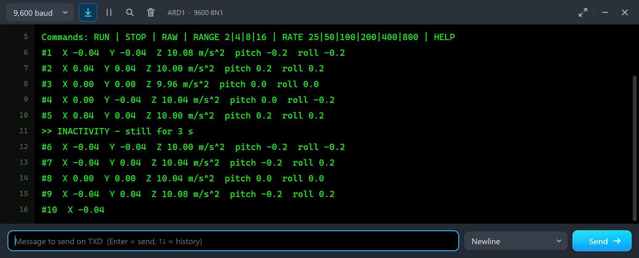
Both UNOs have the serial monitor built in, and it opens at Run. The screenshots use its Simple interface. Node 1 starts like this:
Commands: RUN | STOP | RAW | RANGE 2|4|8|16 | RATE 25|50|100|200|400|800 | HELP
#1  X -0.04  Y -0.04  Z 10.08 m/s^2  pitch -0.2  roll -0.2
#2  X 0.04  Y 0.04  Z 10.00 m/s^2  pitch 0.2  roll 0.2
#3  X 0.00  Y 0.00  Z 9.96 m/s^2  pitch 0.0  roll 0.0
#4  X 0.00  Y -0.04  Z 10.04 m/s^2  pitch 0.0  roll -0.2
#5  X 0.04  Y 0.04  Z 10.00 m/s^2  pitch 0.2  roll 0.2
>> INACTIVITY - still for 3 s
#6  X -0.04  Y -0.04  Z 10.00 m/s^2  pitch -0.2  roll -0.2
Flat on the table, Z carries gravity and X and Y read about zero; the last digit moves by one count either way, as on a real sensor. Note the value: about 10.04 m/s^2, not 9.81. The chip's typical step is 3.9 mg, so 1 g is 256 counts, but the Adafruit library multiplies by 4 mg: 256 x 0.004 x 9.80665 = 10.04. The pitch and the roll are not affected, because they come from the ratio of the axes. After 3 seconds at rest the chip itself reports INACTIVITY on INT1.
Tilt the Board
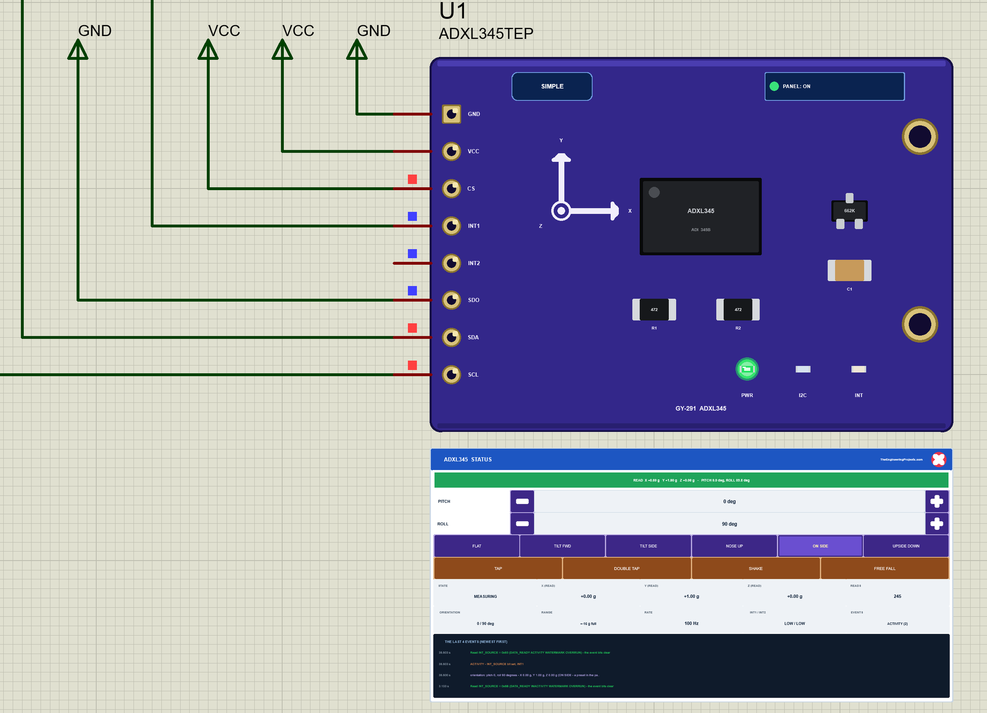
Now let's move the board while the simulation runs. We clicked ON SIDE on U1's STATUS panel with the mouse:
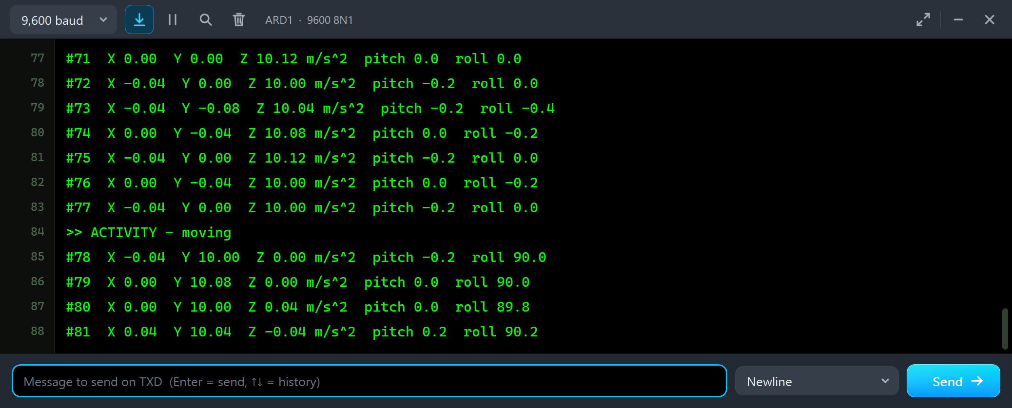
#76  X 0.00  Y -0.04  Z 10.00 m/s^2  pitch 0.0  roll -0.2
#77  X -0.04  Y 0.00  Z 10.00 m/s^2  pitch -0.2  roll 0.0
>> ACTIVITY - moving
#78  X -0.04  Y 10.00  Z 0.00 m/s^2  pitch -0.2  roll 90.0
#79  X 0.00  Y 10.08  Z 0.00 m/s^2  pitch 0.0  roll 90.0
Gravity moved from Z to Y, and the chip saw the change before the sketch did: ACTIVITY came on INT1 because the board moved by more than 0.75 g on an axis. Then three clicks on the pitch's +:
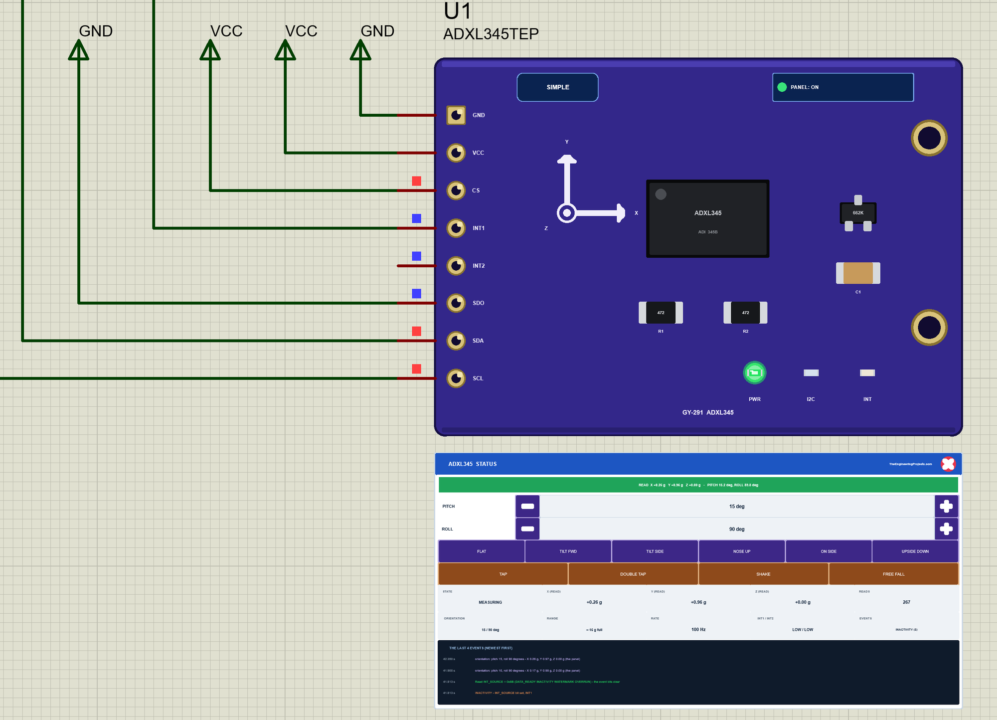
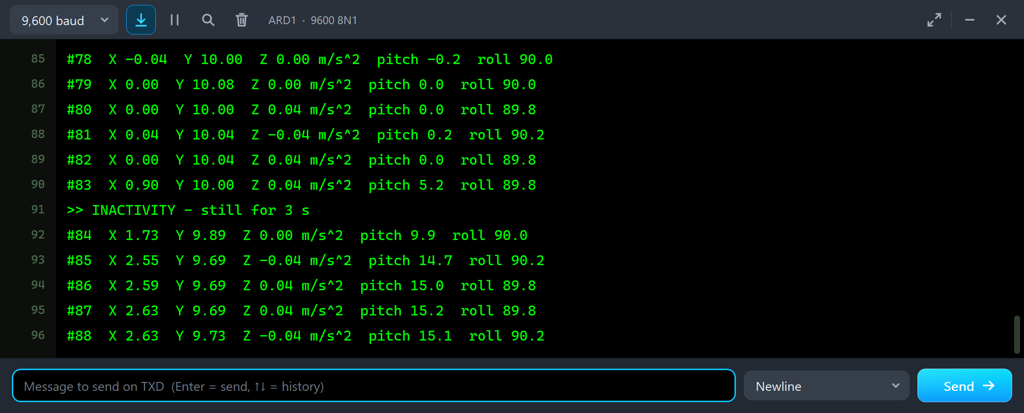
#82  X 0.00  Y 10.04  Z 0.04 m/s^2  pitch 0.0  roll 89.8
#83  X 0.90  Y 10.00  Z 0.04 m/s^2  pitch 5.2  roll 89.8
>> INACTIVITY - still for 3 s
#84  X 1.73  Y 9.89  Z 0.00 m/s^2  pitch 9.9  roll 90.0
#85  X 2.55  Y 9.69  Z -0.04 m/s^2  pitch 14.7  roll 90.2
#86  X 2.59  Y 9.69  Z 0.04 m/s^2  pitch 15.0  roll 89.8
Each click is 5 degrees: X grows with the sine of the pitch, to 2.59 m/s^2 at 15 degrees. These small steps are no activity: each one moves an axis by less than 0.1 g, far below the 0.75 g threshold, and after 3 seconds without a big change the chip reports INACTIVITY again.
Tap It and Drop It
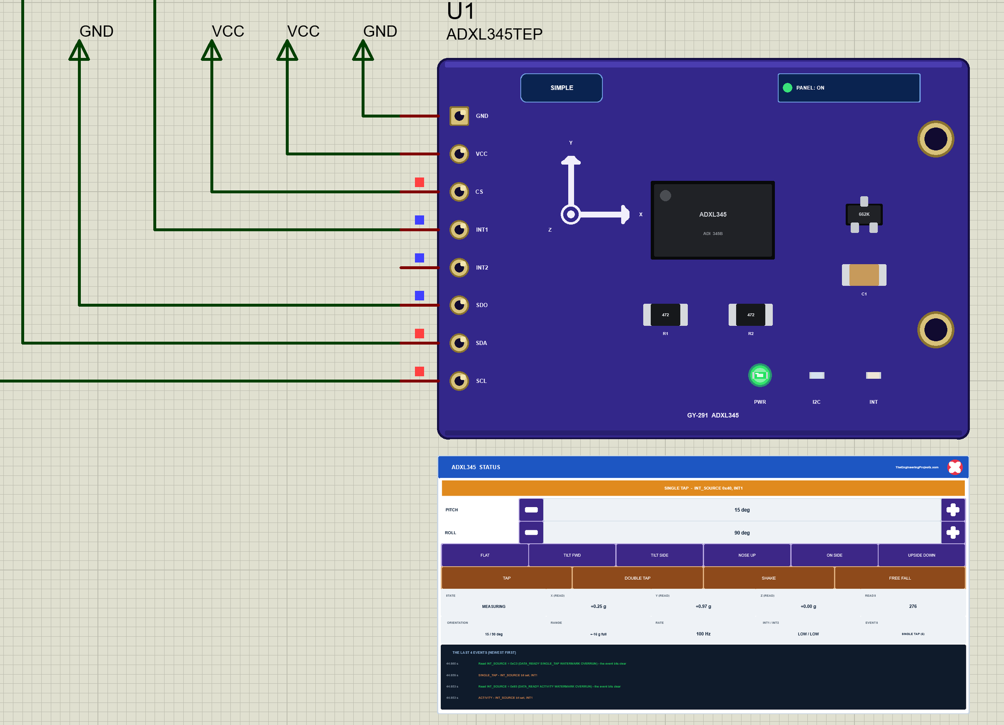
Now the motions. We clicked TAP: a 4 g knock on Z for 12 ms. The banner turned amber:
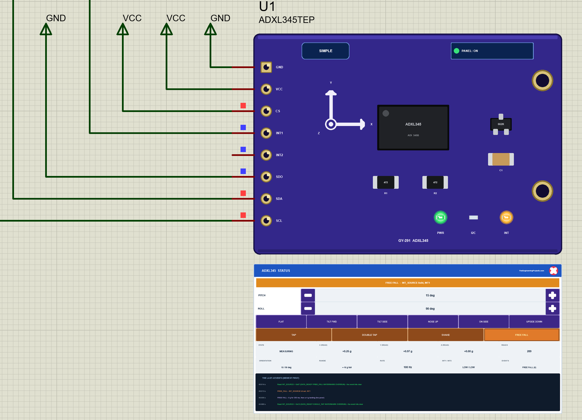
Then FREE FALL: 350 ms of 0 g on all three axes, then a 4 g landing. The INT LED lights on the board:
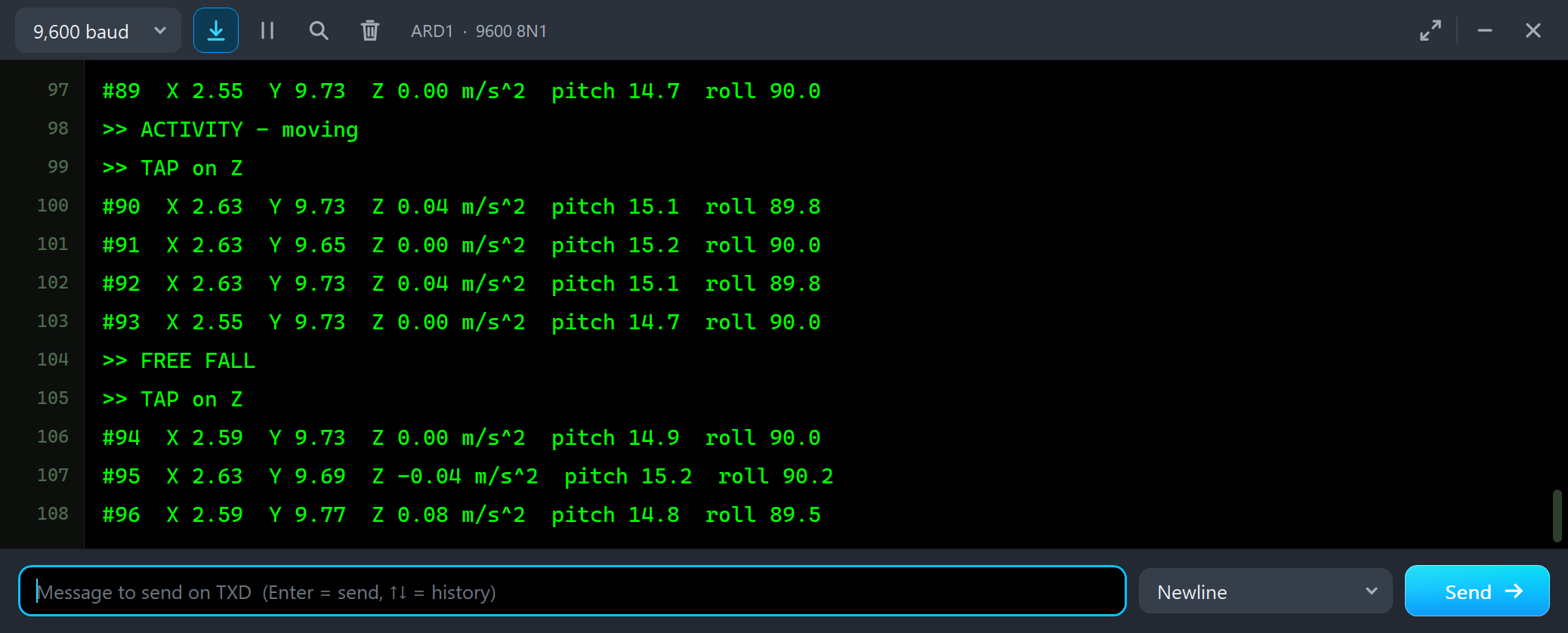
#89  X 2.55  Y 9.73  Z 0.00 m/s^2  pitch 14.7  roll 90.0
>> ACTIVITY - moving
>> TAP on Z
#90  X 2.63  Y 9.73  Z 0.04 m/s^2  pitch 15.1  roll 89.8
#91  X 2.63  Y 9.65  Z 0.00 m/s^2  pitch 15.2  roll 90.0
#92  X 2.63  Y 9.73  Z 0.04 m/s^2  pitch 15.1  roll 89.8
#93  X 2.55  Y 9.73  Z 0.00 m/s^2  pitch 14.7  roll 90.0
>> FREE FALL
>> TAP on Z
#94  X 2.59  Y 9.73  Z 0.00 m/s^2  pitch 14.9  roll 90.0
None of the readings around the tap shows it: the knock lasted 12 ms, and the sketch reads twice a second. The tap function caught it, held INT1 HIGH, and the sketch read INT_SOURCE and ACT_TAP_STATUS, which says the tap was on Z. The fall works the same way: all three axes stayed below 0.56 g for 100 ms, so FREE FALL came first, and the landing's 4 g knock was a tap of its own.
RAW: One Read for All Six Bytes
getEvent() reads X, Y and Z in three separate I2C reads, so at a high data rate they can come from two different samples. RAW reads the six data bytes from 0x32 in one go, as the datasheet advises:
void raw() {
  Wire.beginTransmission(ADXL_ADDR);
  Wire.write(DATAX0);
  Wire.endTransmission();
  Wire.requestFrom(ADXL_ADDR, (uint8_t)6);
  uint8_t b[6];
  for (uint8_t i = 0; i < 6; i++) b[i] = Wire.read();
  const int16_t x = (int16_t)(b[1] << 8 | b[0]), y = (int16_t)(b[3] << 8 | b[2]), z = (int16_t)(b[5] << 8 | b[4]);
  Serial.print(F("RAW:"));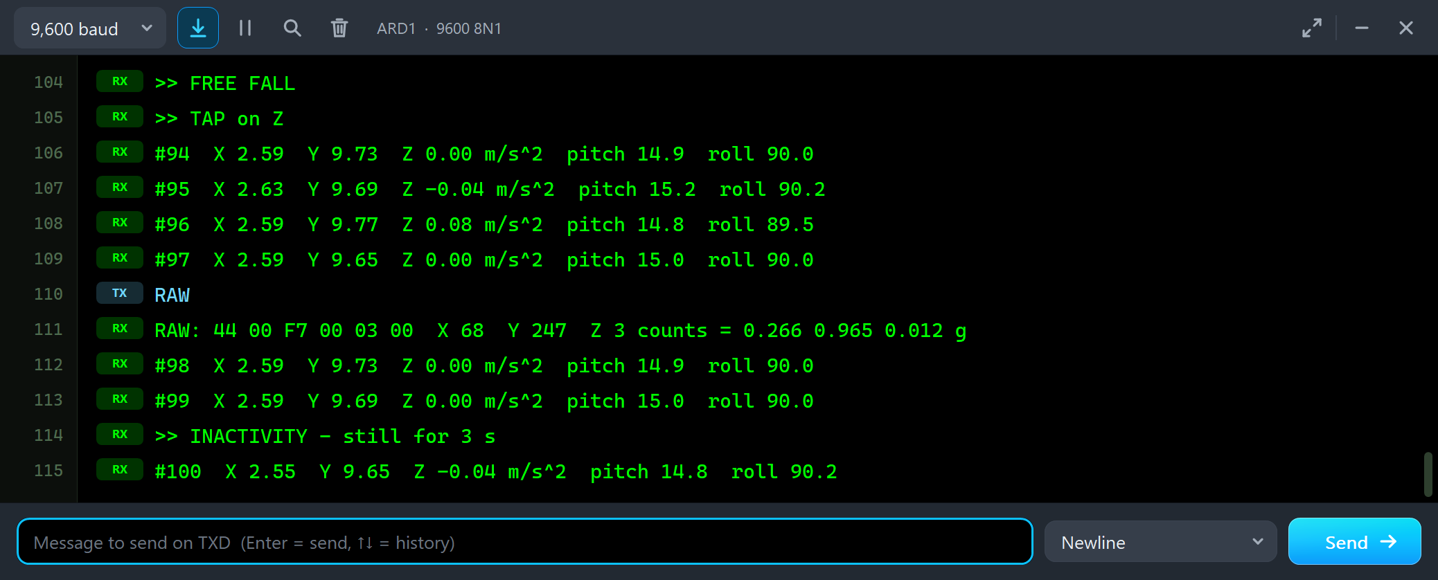
#97  X 2.59  Y 9.65  Z 0.00 m/s^2  pitch 15.0  roll 90.0
RAW
RAW: 44 00 F7 00 03 00  X 68  Y 247  Z 3 counts = 0.266 0.965 0.012 g
#98  X 2.59  Y 9.73  Z 0.00 m/s^2  pitch 14.9  roll 90.0
The bytes come low byte first: 44 00 is X = 0x0044 = 68 counts, F7 00 is Y = 247 and 03 00 is Z = 3. Divided by 256 that is 0.266, 0.965 and 0.012 g: close to the sine and the cosine of 15 degrees, with gravity on Y because the board lies on its side.
The Advance Pop-Up Window
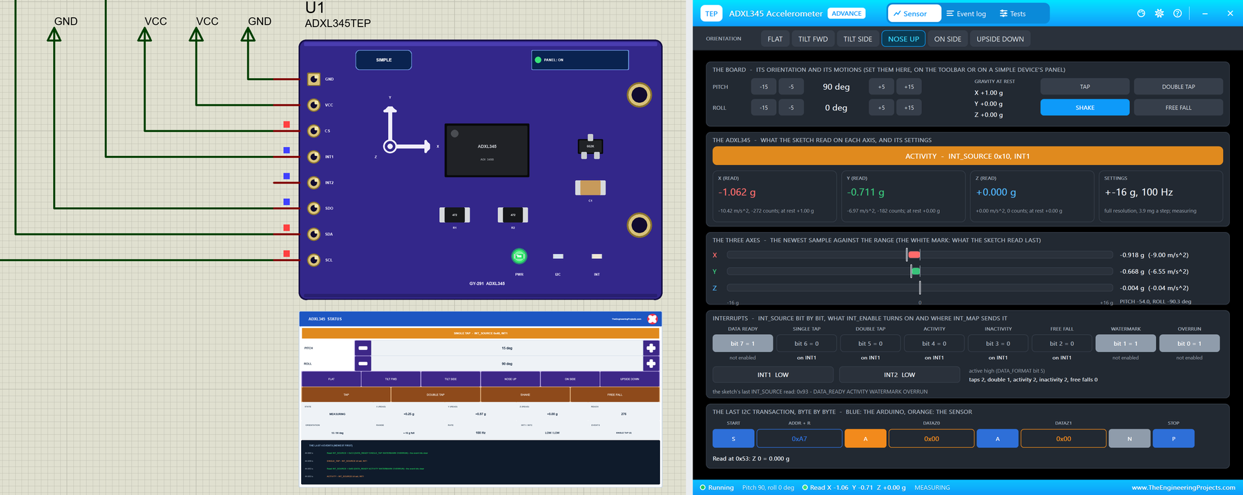
At Run, the Advance module opens its own window, ADXL345 Accelerometer, with the look of our TEP Serial Monitor Advance for Proteus. It has three tabs, Sensor, Event log and Tests, plus Settings and Help behind the gear and question mark icons. The status bar at the bottom always shows the board's tilt, what the sketch read and the state.
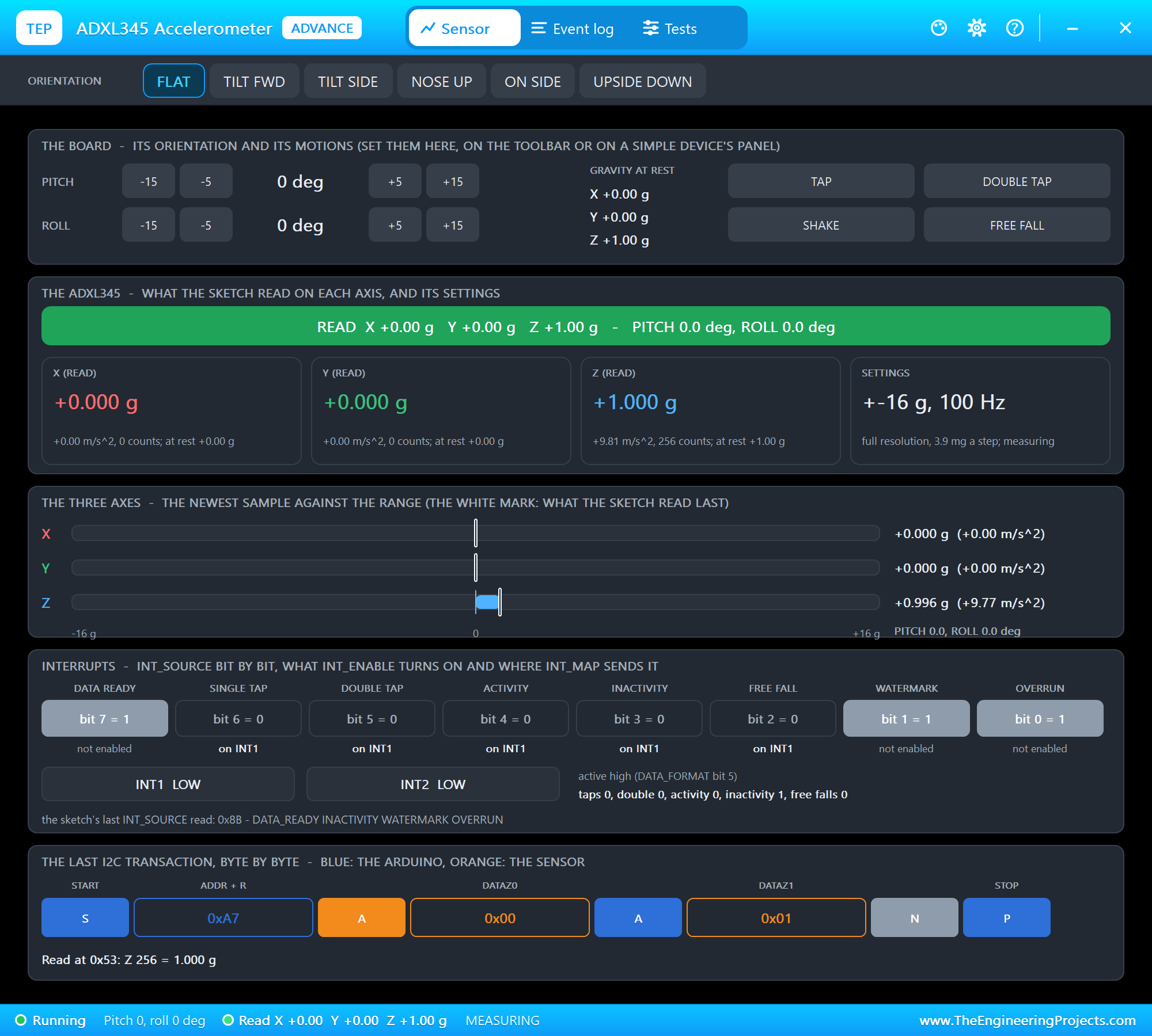
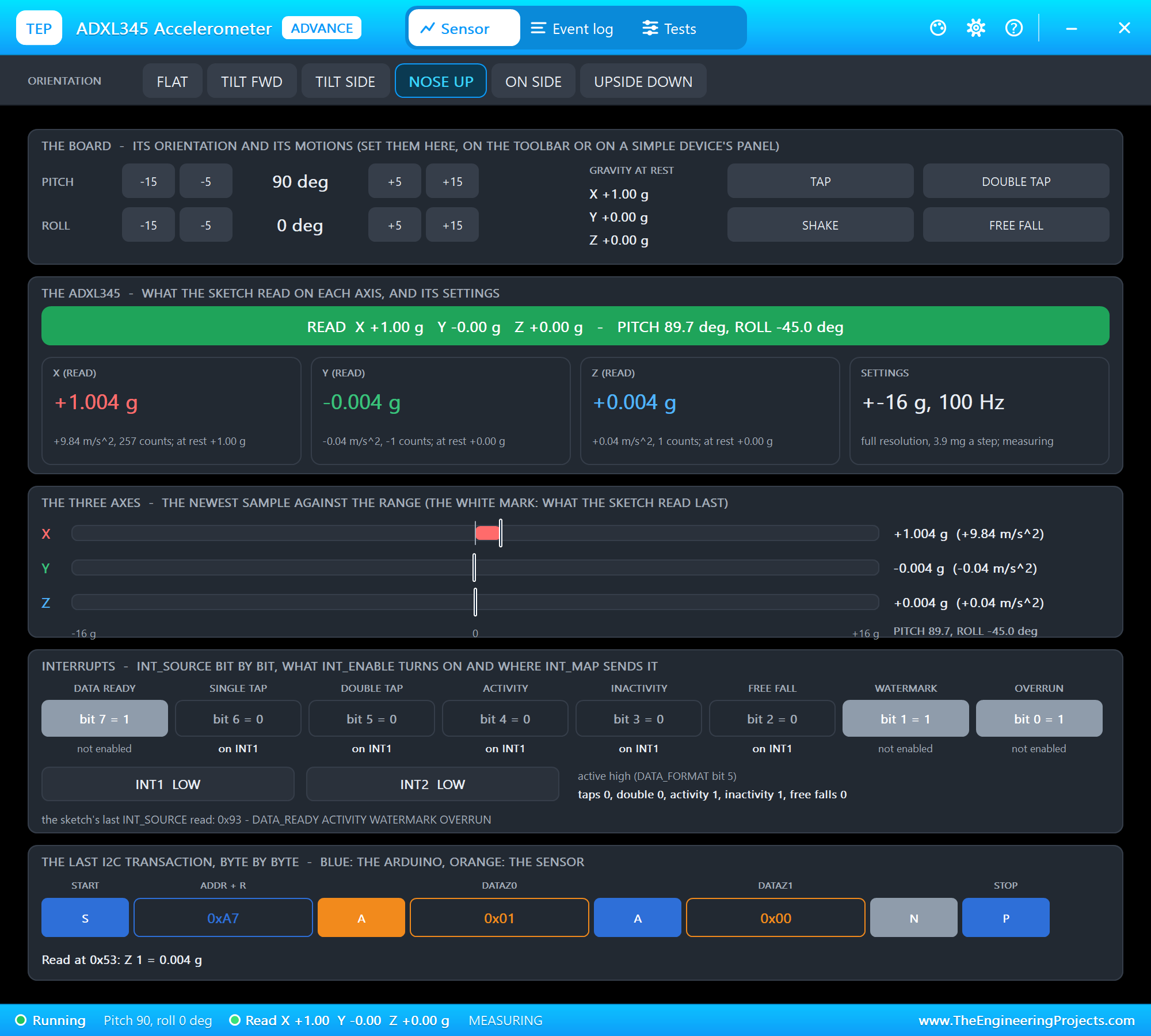
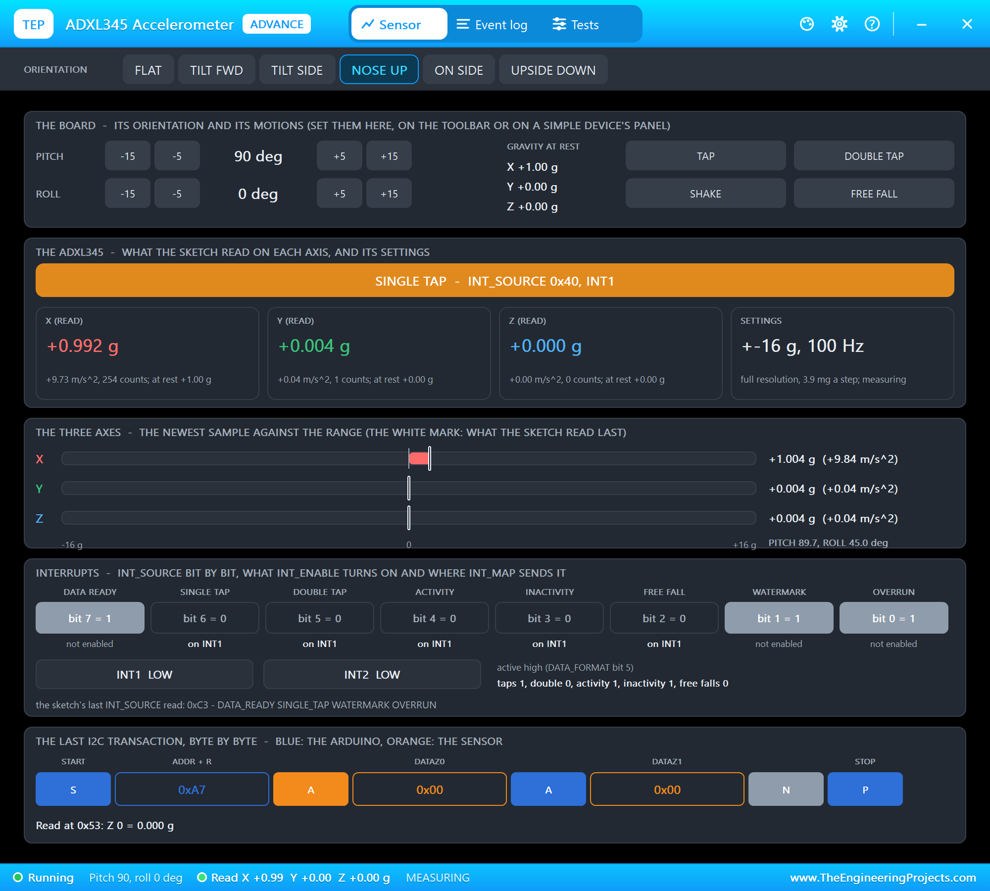
The toolbar carries the six orientations. The top card is the board: the pitch and the roll with -15, -5, +5 and +15 degrees, the gravity on each axis at rest, and the four motions. The ADXL345 card shows the banner, what the sketch read on each axis and the settings. The three axes draws the newest sample against the range, with a white mark where the sketch read last. Interrupts shows INT_SOURCE bit by bit, which functions are enabled and where they go, and the two INT pins. The last card draws the last I2C transaction byte by byte. We clicked NOSE UP:
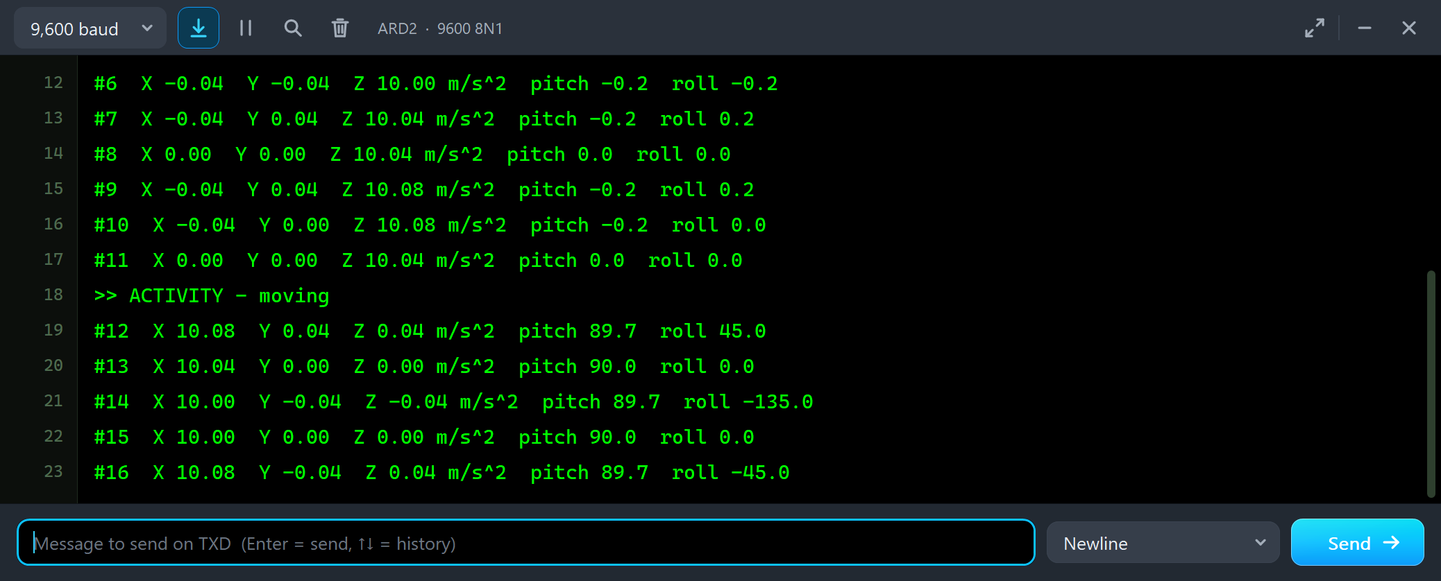
#10  X -0.04  Y 0.00  Z 10.08 m/s^2  pitch -0.2  roll 0.0
#11  X 0.00  Y 0.00  Z 10.04 m/s^2  pitch 0.0  roll 0.0
>> ACTIVITY - moving
#12  X 10.08  Y 0.04  Z 0.04 m/s^2  pitch 89.7  roll 45.0
#13  X 10.04  Y 0.00  Z 0.00 m/s^2  pitch 90.0  roll 0.0
#14  X 10.00  Y -0.04  Z -0.04 m/s^2  pitch 89.7  roll -135.0
Look at the roll: 45.0, 0.0, -135.0. With the nose straight up, Y and Z hold only noise, and the roll, the angle between them, has no meaning. A real sensor does the same; a project that must know its roll at 90 degrees of pitch needs a gyroscope too. Then we clicked TAP:
And DOUBLE TAP, two knocks 200 ms apart:
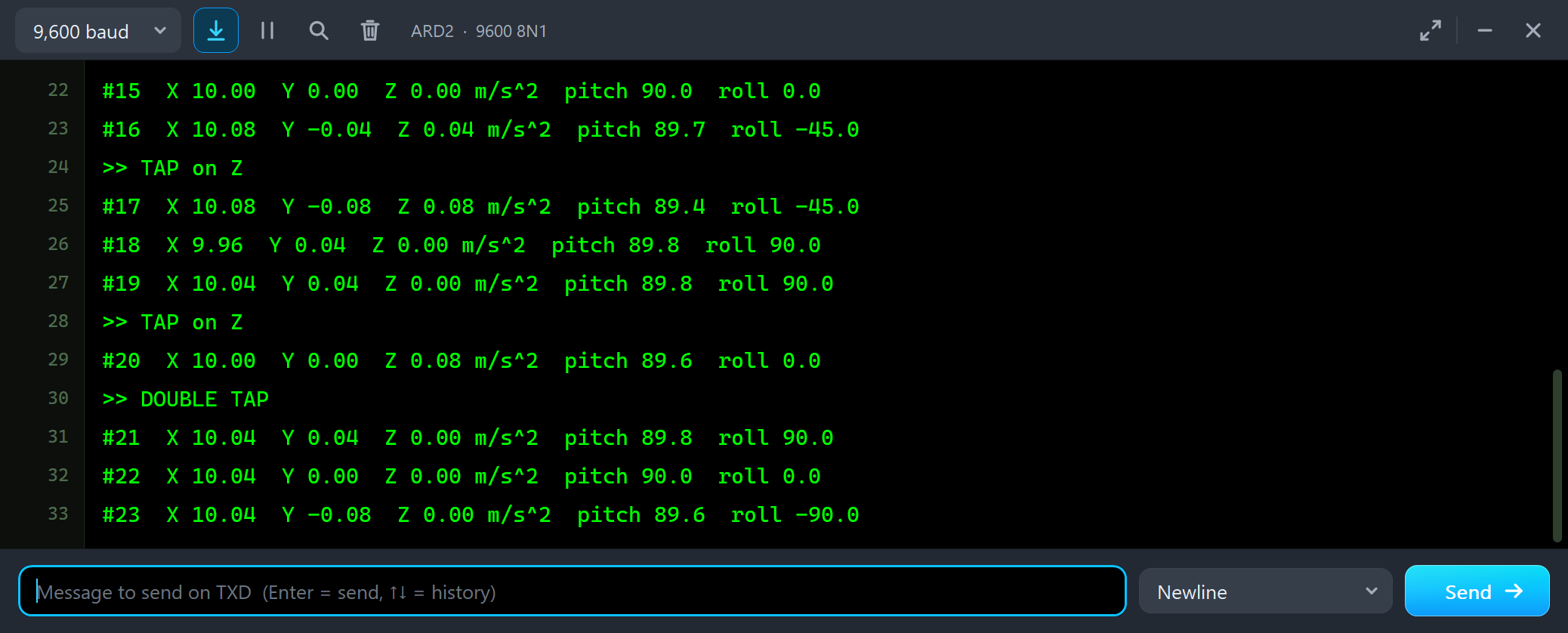
#16  X 10.08  Y -0.04  Z 0.04 m/s^2  pitch 89.7  roll -45.0
>> TAP on Z
#17  X 10.08  Y -0.08  Z 0.08 m/s^2  pitch 89.4  roll -45.0
#18  X 9.96  Y 0.04  Z 0.00 m/s^2  pitch 89.8  roll 90.0
#19  X 10.04  Y 0.04  Z 0.00 m/s^2  pitch 89.8  roll 90.0
>> TAP on Z
#20  X 10.00  Y 0.00  Z 0.08 m/s^2  pitch 89.6  roll 0.0
>> DOUBLE TAP
A double tap is always a tap first: the first knock sets SINGLE_TAP, and the second, after the 100 ms of Latent and inside the 250 ms Window, sets DOUBLE_TAP. A sketch that wants only double taps enables only that bit. After 3 seconds at rest:
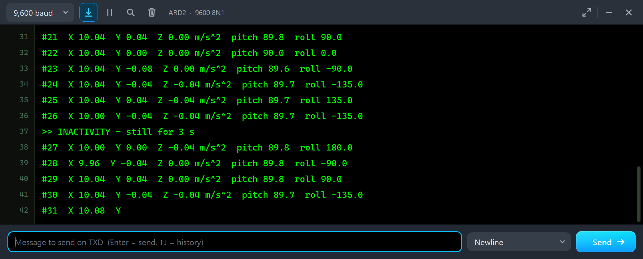
#26  X 10.00  Y -0.04  Z -0.04 m/s^2  pitch 89.7  roll -135.0
>> INACTIVITY - still for 3 s
#27  X 10.00  Y 0.00  Z -0.04 m/s^2  pitch 89.8  roll 180.0
Then SHAKE, 5 Hz along X for 1.5 seconds:
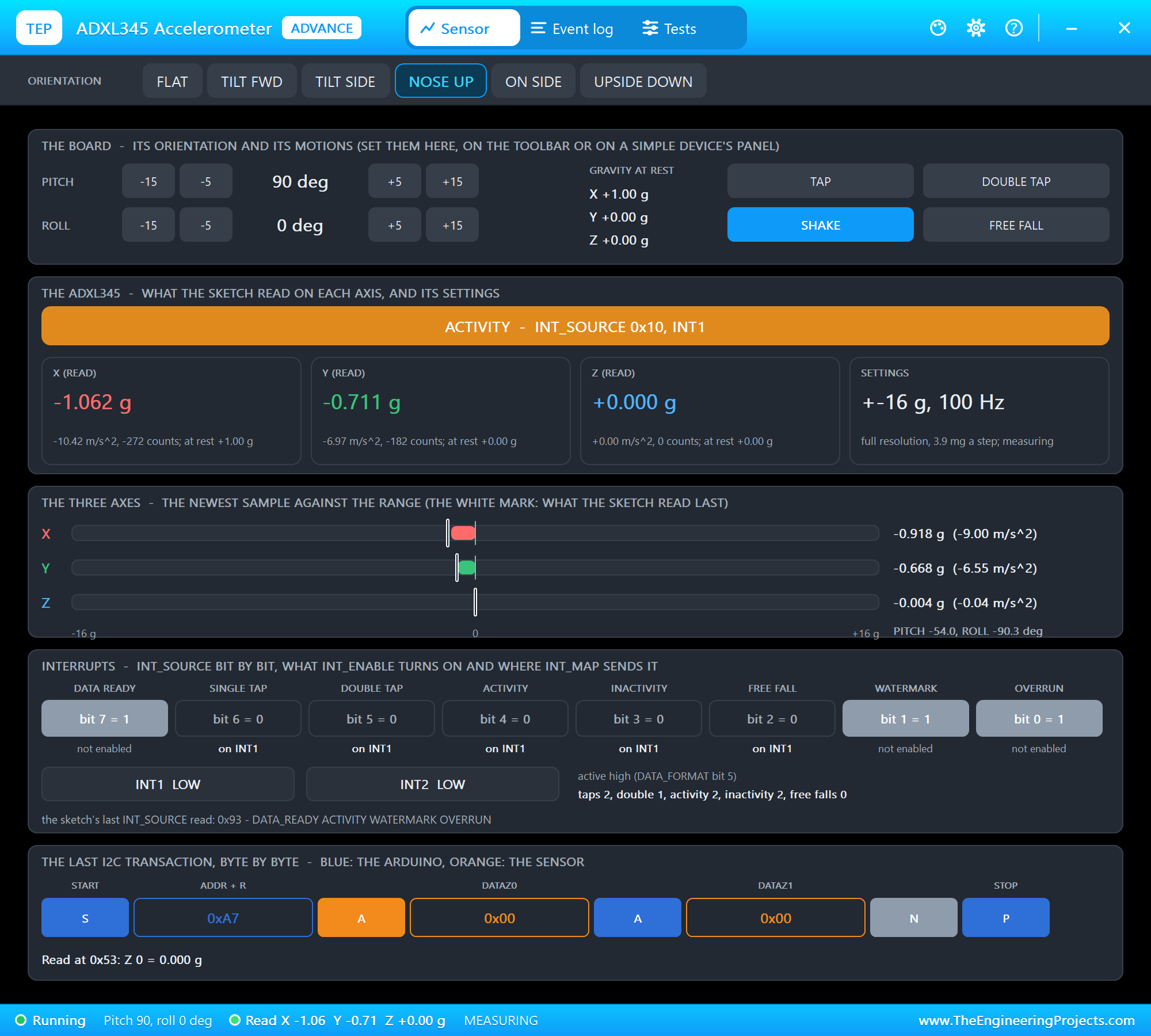
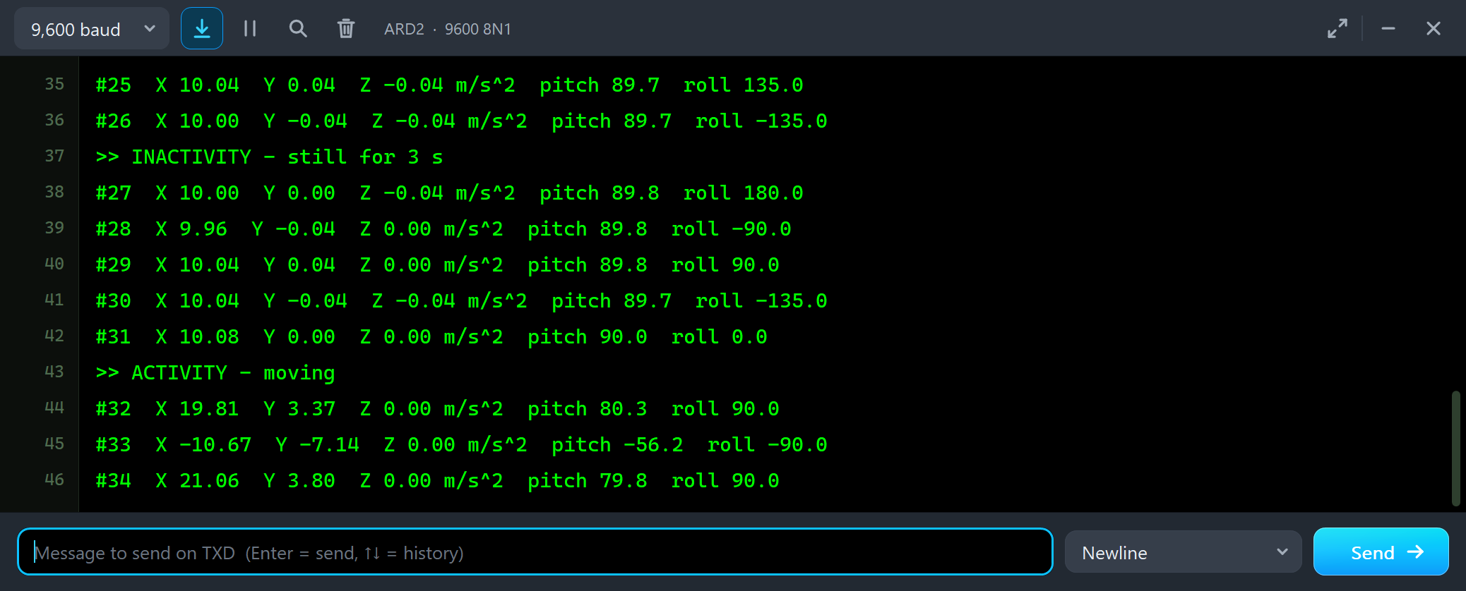
#31  X 10.08  Y 0.00  Z 0.00 m/s^2  pitch 90.0  roll 0.0
>> ACTIVITY - moving
#32  X 19.81  Y 3.37  Z 0.00 m/s^2  pitch 80.3  roll 90.0
#33  X -10.67  Y -7.14  Z 0.00 m/s^2  pitch -56.2  roll -90.0
#34  X 21.06  Y 3.80  Z 0.00 m/s^2  pitch 79.8  roll 90.0
Each line catches the shake at another moment, from -10.67 to 21.06 m/s^2, and the pitch with it: during a shake the angles mean nothing, because the sensor feels the movement and gravity together. Last, FREE FALL:
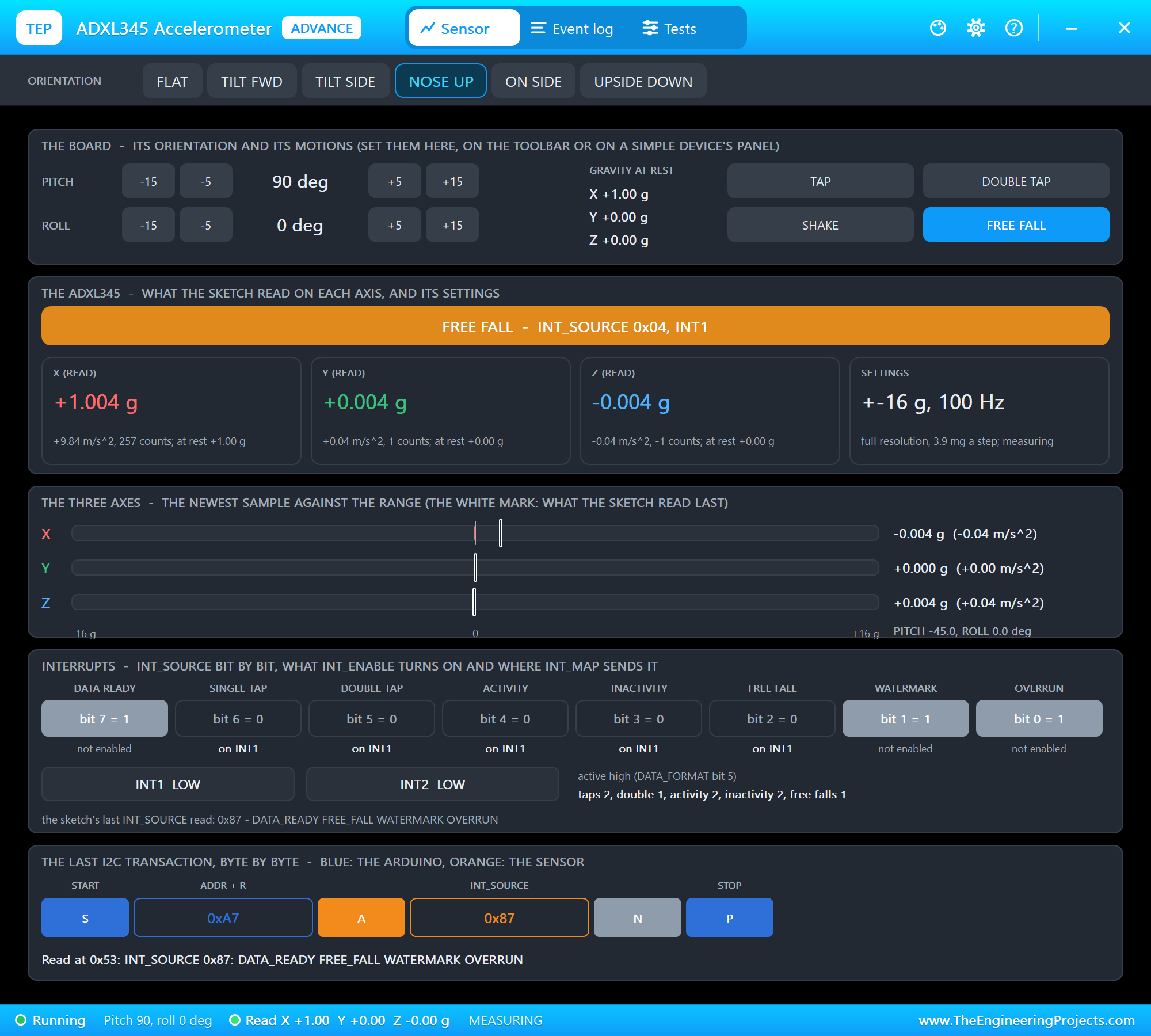
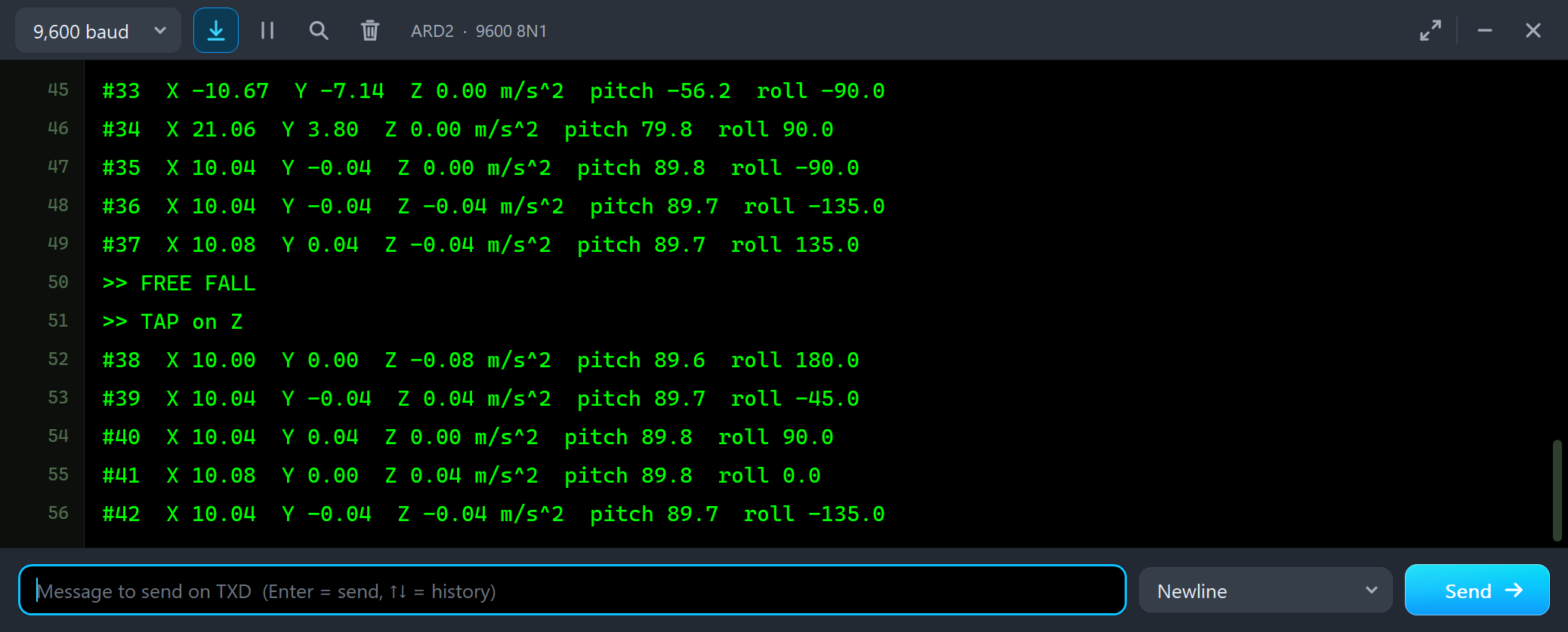
#35  X 10.04  Y -0.04  Z 0.00 m/s^2  pitch 89.8  roll -90.0
#36  X 10.04  Y -0.04  Z -0.04 m/s^2  pitch 89.7  roll -135.0
#37  X 10.08  Y 0.04  Z -0.04 m/s^2  pitch 89.7  roll 135.0
>> FREE FALL
>> TAP on Z
#38  X 10.00  Y 0.00  Z -0.08 m/s^2  pitch 89.6  roll 180.0
The three bars dropped to zero while the board fell: in free fall an accelerometer reads nothing at all. No reading line caught the 350 ms, but INT1 did. A drop logger or a hard-disk protector works exactly like this.
RATE and RANGE
RANGE sets plus or minus 2, 4, 8 or 16 g and RATE the data rate. We typed RANGE 2, RATE 25 and RAW:
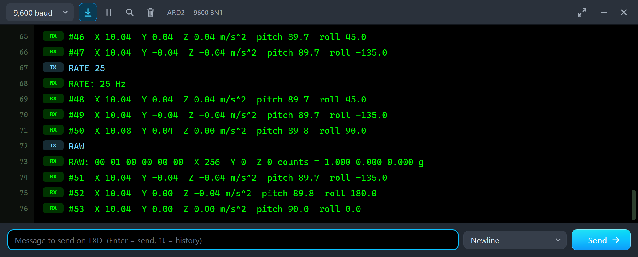
RATE 25
RATE: 25 Hz
#48  X 10.04  Y 0.04  Z 0.04 m/s^2  pitch 89.7  roll 45.0
#49  X 10.04  Y -0.04  Z -0.04 m/s^2  pitch 89.7  roll -135.0
#50  X 10.08  Y 0.04  Z 0.00 m/s^2  pitch 89.8  roll 90.0
RAW
RAW: 00 01 00 00 00 00  X 256  Y 0  Z 0 counts = 1.000 0.000 0.000 g
With full resolution the scale stays the same at every range, so 1 g is still 256 counts: 00 01 on X. A smaller range only lowers the limit: at plus or minus 2 g a 4 g tap stops at 2 g in the data, while the tap function, which works on the whole signal, still sees it.
The Test Tools
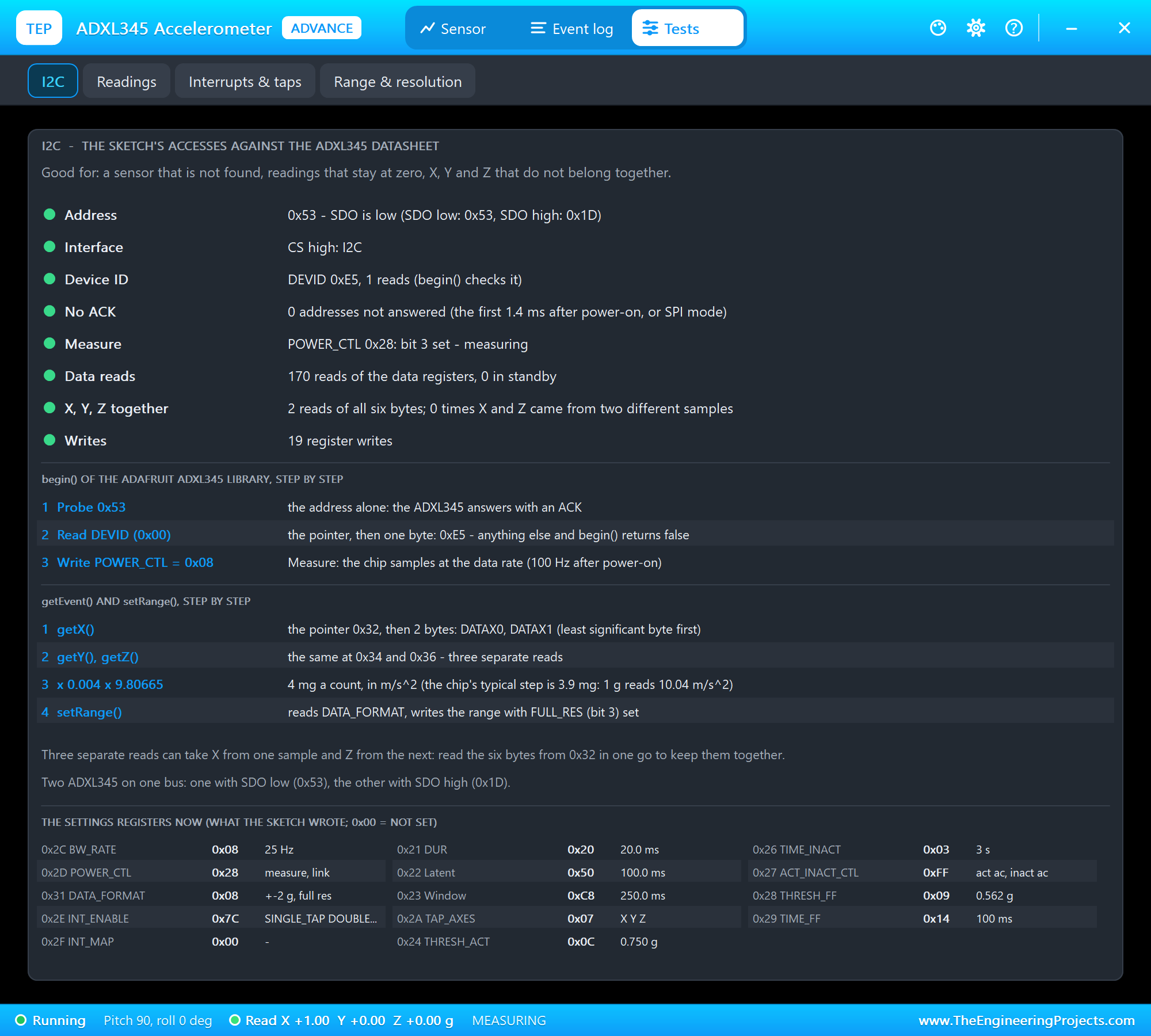
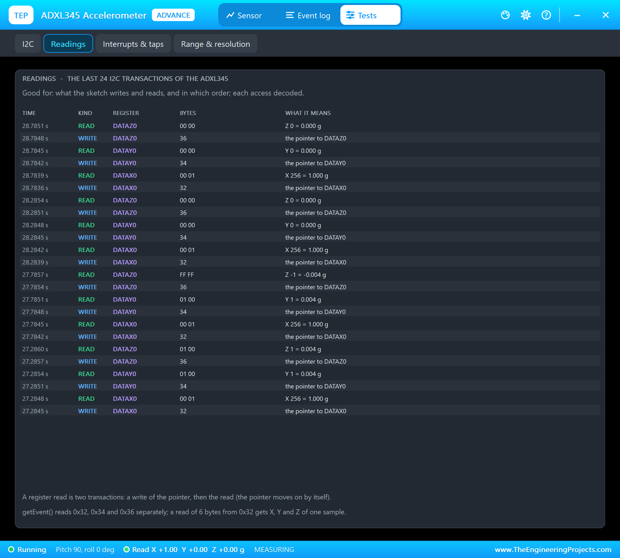
The I2C tool is the one to open for a sensor that is not found, readings that stay at zero or X, Y and Z that do not belong together. It checks the address against SDO, I2C against SPI mode, DEVID, the Measure bit and the data reads, shows begin() and getEvent() step by step, and lists the settings registers as the sketch left them. The Readings tool lists the last 24 transactions:
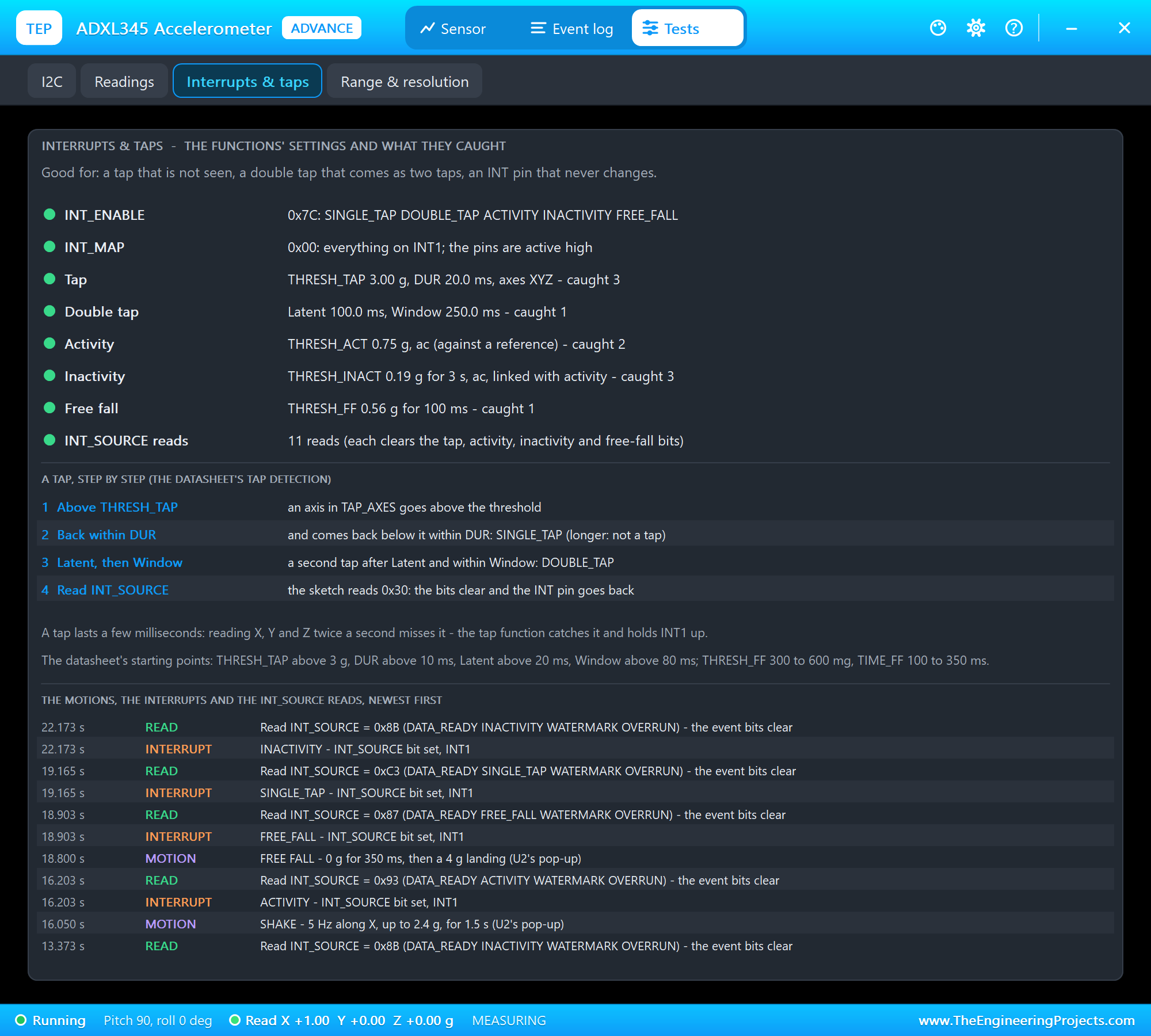
Interrupts and taps is for a tap that is not seen, a double tap that comes as two taps or an INT pin that never changes: each function with its thresholds and times, what it caught, a tap step by step and the list of motions, interrupts and INT_SOURCE reads. Range and resolution explains the numbers:
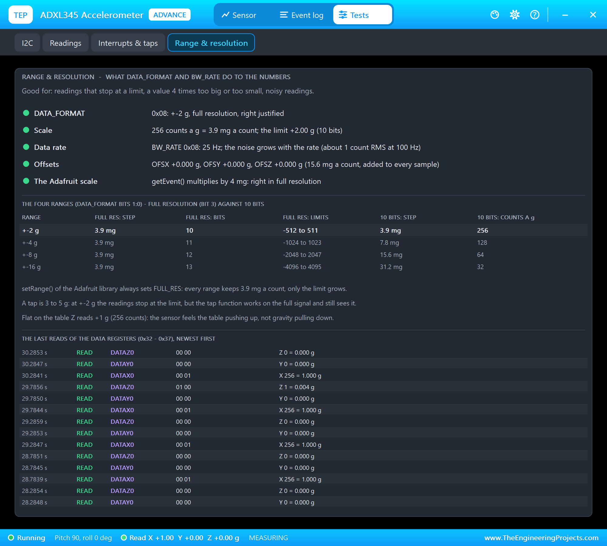
It decodes DATA_FORMAT and BW_RATE, checks that the Adafruit scale of 4 mg fits the format, compares the four ranges in full resolution and in 10 bits, and decodes the last data reads.
The Event Log
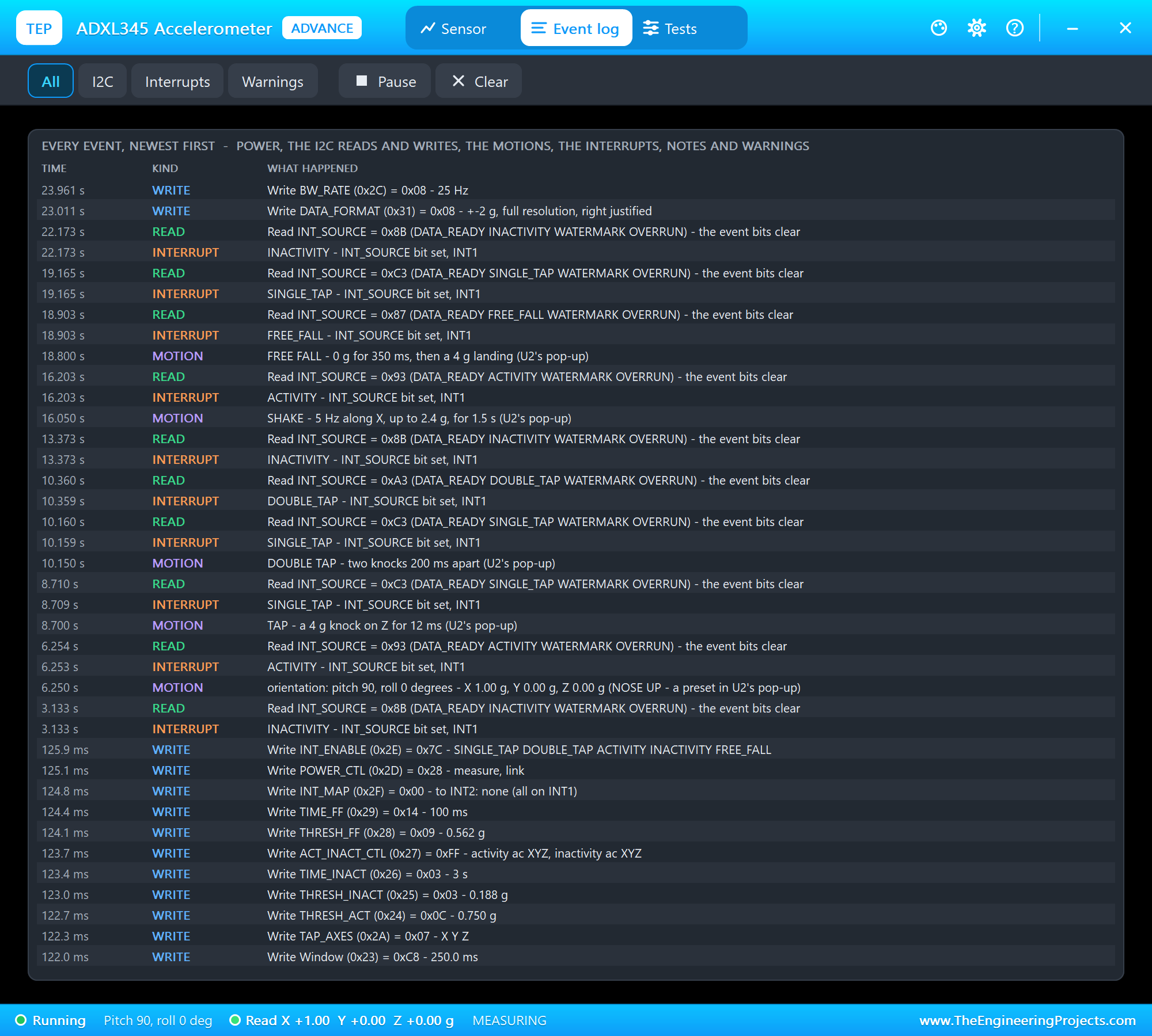
The Event log lists everything that happened, newest first: the power, the register writes, the data reads, the motions with where they came from, the interrupts, notes and warnings. Filter it by I2C, interrupts or warnings, pause it, or clear it.
The Simulation Log
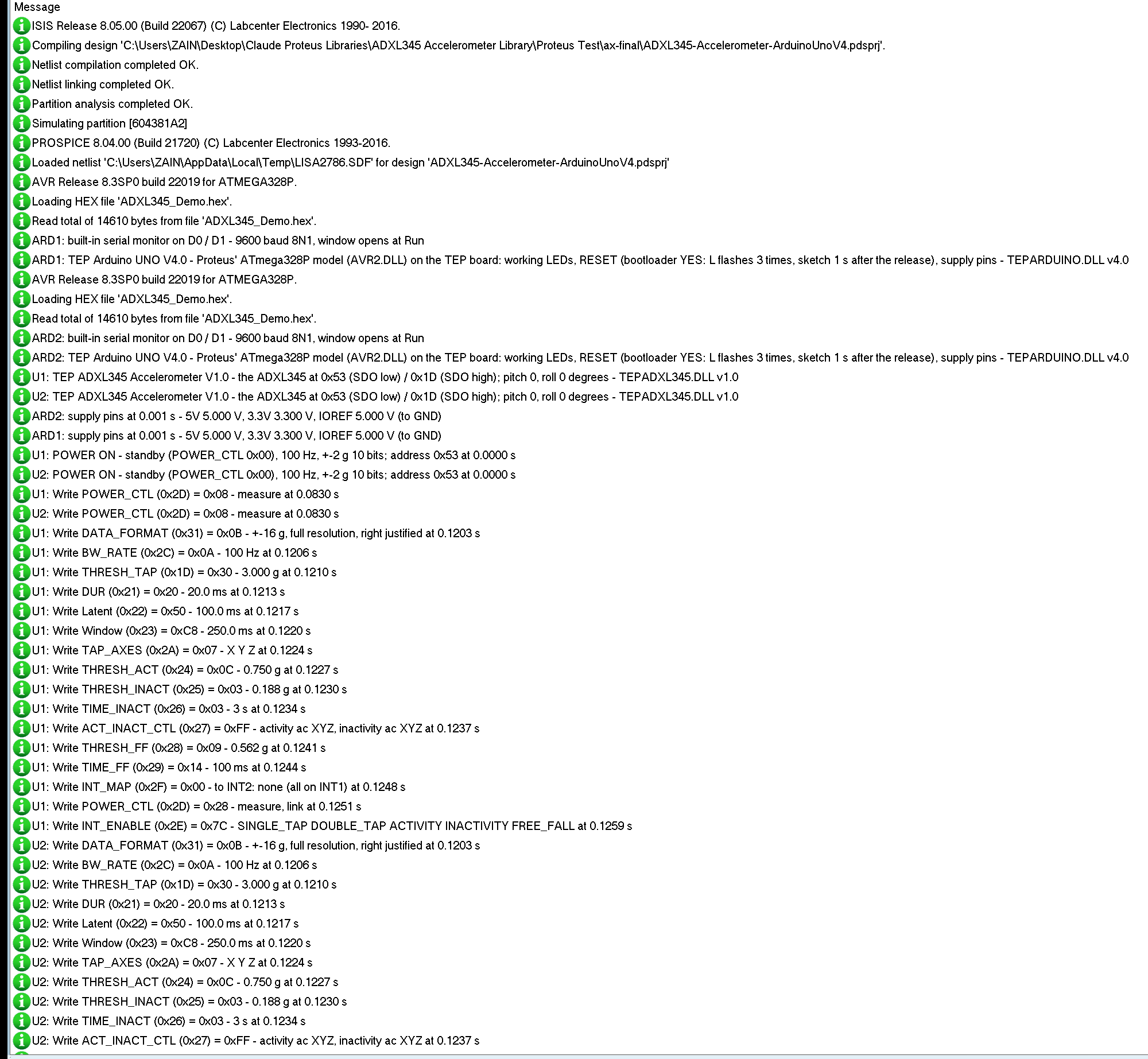
The module also writes to the simulation log of Proteus, with the exact simulation time. This part shows begin() and the set-up of the functions:
U1: TEP ADXL345 Accelerometer V1.0 - the ADXL345 at 0x53 (SDO low) / 0x1D (SDO high); pitch 0, roll 0 degrees - TEPADXL345.DLL v1.0
U1: POWER ON - standby (POWER_CTL 0x00), 100 Hz, +-2 g 10 bits; address 0x53 at 0.0000 s
U1: Write POWER_CTL (0x2D) = 0x08 - measure at 0.0830 s
U1: Write DATA_FORMAT (0x31) = 0x0B - +-16 g, full resolution, right justified at 0.1203 s
U1: Write BW_RATE (0x2C) = 0x0A - 100 Hz at 0.1206 s
U1: Write THRESH_TAP (0x1D) = 0x30 - 3.000 g at 0.1210 s
U1: Write DUR (0x21) = 0x20 - 20.0 ms at 0.1213 s
U1: Write Latent (0x22) = 0x50 - 100.0 ms at 0.1217 s
U1: Write Window (0x23) = 0xC8 - 250.0 ms at 0.1220 s
U1: Write POWER_CTL (0x2D) = 0x28 - measure, link at 0.1251 s
U1: Write INT_ENABLE (0x2E) = 0x7C - SINGLE_TAP DOUBLE_TAP ACTIVITY INACTIVITY FREE_FALL at 0.1259 s
The chip starts in standby with the power-on defaults, and begin() sets Measure at 0.0830 s. Each write is decoded: 0x30 in THRESH_TAP is 3 g at 62.5 mg a step, 0x20 in DUR is 20 ms at 625 us a step.
How the Model Works
The module is a digital model. VCC and GND power it, CS and SDO choose the interface and the address, and SCL and SDA are the I2C bus: Proteus runs every edge from the Arduino with its exact time, and the model pulls SDA low to acknowledge and to send. The chip takes a sample at its data rate from the board's tilt and motion, with about one count of noise, clips it at the range and stores it in the format DATA_FORMAT asks for. While the board moves, the tap detector checks the acceleration 1600 times a second; activity, inactivity and free fall check every sample. When a function fires, INT1 or INT2 changes at the simulation time of that sample.
Troubleshooting
- "ADXL345 not found": no power on VCC and GND, SDA and SCL swapped or missing, CS low, or the wrong address for SDO; the PWR LED is off or the I2C LED never flashes.
- X, Y and Z stay at 0: the chip is in standby; set the Measure bit, as begin() does.
- Z reads 10.04 m/s^2: the Adafruit library's 4 mg against the chip's 3.9 mg; the angles are right.
- Values 8 times too small: 10 bits at plus or minus 16 g; setRange() sets full resolution, a hand-written DATA_FORMAT may not.
- No TAP on the monitor: INT1 not on D2, THRESH_TAP above the knock, DUR shorter than the knock, or INT_SOURCE never read, so INT1 stays HIGH and no new rising edge comes.
- A double tap comes as two taps: the second knock came inside Latent or after Window.
- No part or no monitor: TEPADXL345.DLL or TEPARDUINO.DLL is missing from MODELS and the project folder; a closed monitor opens again with a click on the UNO's USB port.
Things to Know Before Using a Real ADXL345
- CS to VCC: a CS left low puts the ADXL345 in SPI mode, and it never answers on I2C.
- Two on one bus: one with SDO to GND (0x53), the other with SDO to VCC (0x1D).
- Read all six bytes: when X, Y and Z must come from the same moment, read them in one go, as RAW does.
- Mount it firmly: a loose board rattles, and the tap function counts the rattle.
Limitations of the Simulation
- Not modelled: SPI, the FIFO (only bypass), the sleep timing, the self-test force, the chip's own sensitivity and offset errors (the datasheet: 3.5 to 4.3 mg a count), temperature drift and the I2C clock stretching. The motions are fixed shapes: one knock, two knocks, a 5 Hz shake, a fall and a landing.
- The LEDs, the badge, the panel button and the panels are TEP additions.
- The model is our own, written from the ADXL345 datasheet. This library is not made or endorsed by Analog Devices, Adafruit, the makers of the GY-291 module or Labcenter.
- Licences: the demo sketch uses the Adafruit ADXL345 library 1.3.4 (BSD), Adafruit Unified Sensor 1.1.15 (Apache 2.0) and Adafruit BusIO 1.17.4 (MIT), which are not shipped; install them from the Library Manager. The demo's HEX file contains them and the Arduino AVR core 1.8.6 with LGPL-licensed code; the licence texts and the source links are in the README.
- Tested in Proteus 8.5 in October 2026 (the demo as shipped on two Arduino UNO V4.0 boards with their built-in monitors: both nodes reading flat, ON SIDE, the pitch buttons, TAP, FREE FALL and RAW on node 1 with the mouse, the red X and PANEL; NOSE UP, TAP, DOUBLE TAP, SHAKE, FREE FALL, RANGE, RATE and RAW on node 2, the four tools; 67.7 s of simulation took 128 s, about 0.5 x real time with the pop-up and both monitors open). Proteus 7 is not supported.
So, that was all about the ADXL345 Accelerometer Library for Proteus V1.0. I hope the registers, the range and the interrupts are clear now, and that your tilt sensor or drop detector catches every tap from the first run. If you use the ADXL345 Accelerometer Library for Proteus in a project, please share it in the comments or in our forum, and if you have any questions, ask in the comments and I will help you out. Till the next tutorial, take care and have fun!