


MPU6050 Proteus Library


Hello friends, I hope you are doing well. In today's tutorial, I am going to share our MPU6050 Proteus Library. With this library, we can connect an MPU6050 motion sensor to an Arduino Uno and read acceleration, angular velocity and temperature in a complete simulation. The sensor includes seven interactive controls, so we can change each input while the Arduino program is running.
We will start with the purpose of the sensor, download and install the library, connect the circuit and run the supplied example. After that, we will understand the Arduino code and the calculations used to display its measurements. The package includes the wired Proteus project, compiled HEX and editable sketch, so you can follow the first experiment without building the firmware yourself.
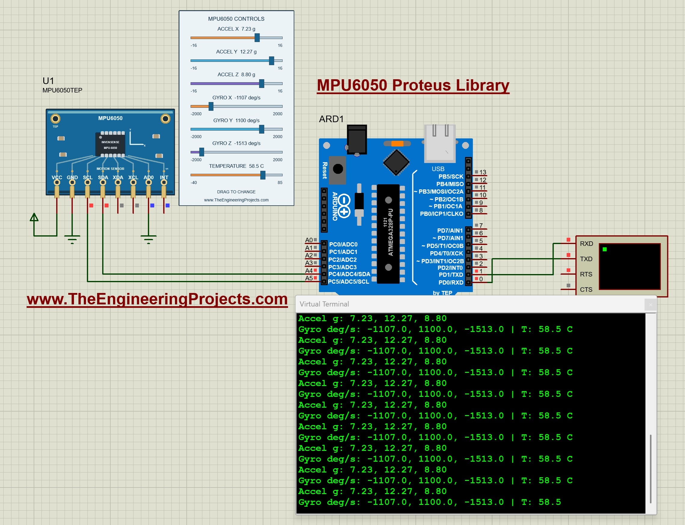
The package targets Proteus 8.5 with AVR simulation support and uses our TEP Arduino UNO V3.0 board at 16 MHz. The running example below shows the seven controls beside the sensor and the corresponding readings in the Virtual Terminal. Let us first understand what those numbers represent before we install the files.
What Is the MPU6050 Sensor?
The MPU6050 combines a three-axis accelerometer and a three-axis gyroscope. The accelerometer provides measurements along the X, Y and Z axes, while the gyroscope measures angular velocity about those axes. Together, these are the six motion channels commonly described as a six-axis inertial sensor. The device also provides an internal temperature reading.
Acceleration and angular velocity describe different quantities. Acceleration is related to a change in velocity, while angular velocity describes how quickly something rotates. An accelerometer also responds to gravity when stationary. A gyroscope reporting 90 degrees per second describes a rotation rate, not an angle of 90 degrees.
In our example, acceleration is displayed in g, angular velocity in degrees per second, and temperature in degrees Celsius. One standard g corresponds to 9.80665 meters per second squared. The default input of 1 g on Z represents the gravity contribution for the example's resting orientation.
The MPU6050 communicates with the Arduino through I2C. We use SDA and SCL for the data exchange instead of connecting each measurement to a separate analog input. The Arduino configures the sensor and reads its measurement registers through the programming library.
Our Proteus component appears as MPU6050TEP. Its controls supply simulated sensor inputs; they do not measure movement of your computer or a physical board. You can read our Introduction to MPU6050 for additional background, then use this tutorial to work through the simulation.
Download the MPU6050 Library for Proteus
First of all, download the package using the button below. Extract the complete archive into a normal folder before opening the simulation. Keep the directory structure together so the project can find its firmware and model files.
Download MPU6050 Proteus Library V1.0 and Arduino SimulationThe supplied archive is named MPU6050-TEP-v1.0-test.zip and retains its original test-package notes. The screenshots in this tutorial show the supplied circuit before and during a run. The download targets Proteus 8.5; compatibility with Proteus 7 or other releases is not established by these screenshots.
| Folder or file | Purpose |
|---|---|
| Proteus Library Files | TEPMPU6050.LIB and the TEP Arduino UNO V3.0 LIB/IDX files used to place the devices. |
| Proteus Model Files | TEPMPU6050.DLL, which provides the functional sensor model. |
| Proteus Simulation | The connected MPU6050-ArduinoUnoV3.pdsprj project, MPU6050_Demo.hex and a local copy of the sensor DLL. |
| Arduino Code | The sketch, exact programming-library sources, AVR core archive and firmware rebuild script. |
| Model Source | The sensor implementation, I2C engine and Proteus model adapter. |
| Documentation | Model capabilities, limitations and third-party notices. |
The Proteus files and Arduino libraries do different jobs. The LIB defines the component that we place on the schematic, the DLL supplies its simulated behavior, and the Arduino library gives our sketch functions for communicating with it. Installing the Arduino library alone will not make MPU6050TEP appear in Proteus.
How to Install the MPU6050 Proteus Library
Save your current work and close Proteus before installing the files. We will add the sensor library first, then make sure its simulation model is available.
- Open the extracted Proteus Library Files folder.
- Copy
TEPMPU6050.LIBinto the library directory configured for your Proteus installation. - Copy
ArduinoV3TEP.LIBandArduinoV3TEP.IDXfrom the same folder if our TEP Arduino UNO V3.0 library is not already installed. - Open Proteus Model Files and copy
TEPMPU6050.DLLinto the configured ProteusMODELSdirectory. - Restart Proteus, open Pick Devices using the P button and search for MPU6050TEP.
- Select the sensor and place it on the schematic, or open the supplied project to use the completed circuit.
Use the folders your installation actually searches. Their locations can vary with the Proteus version and installation layout. The sensor is supplied as a native LIB; this archive does not include a separate TEPMPU6050.IDX. Do not rename the Arduino index file or copy an unrelated sensor index to create one.
Keep the additional DLL inside the Proteus Simulation folder beside the project. The sensor uses that functional model; the file MPU6050_Demo.hex belongs to the Arduino's Program File property. There is no separate sensor HEX to load into MPU6050TEP.
The included Uno comes from our Arduino Library for Proteus V3.0. Start with that board and the supplied project so that the processor, wiring and firmware match the demonstration. You can make your own circuit after the first successful run.
MPU6050 Pinout and Arduino Uno Connections
The module has eight labeled pins along its lower edge. In the default orientation, they are VCC, GND, SCL, SDA, XDA, XCL, AD0 and INT. Begin each wire at the exposed pin endpoint below the board rather than at the printed label.
| Sensor pin | Connection | Purpose in this tutorial |
|---|---|---|
| VCC | Positive supply rail | Enables the powered digital sensor model. |
| GND | Common ground | Provides the shared reference. |
| SCL | Arduino Uno A5 | I2C clock. |
| SDA | Arduino Uno A4 | I2C data. |
| XDA | Unconnected | Auxiliary data pin; its function is not implemented in this model. |
| XCL | Unconnected | Auxiliary clock pin; its function is not implemented in this model. |
| AD0 | Ground | Selects the seven-bit I2C address 0x68. |
| INT | Unconnected | The supplied sketch polls for readings and does not use the interrupt pin. |
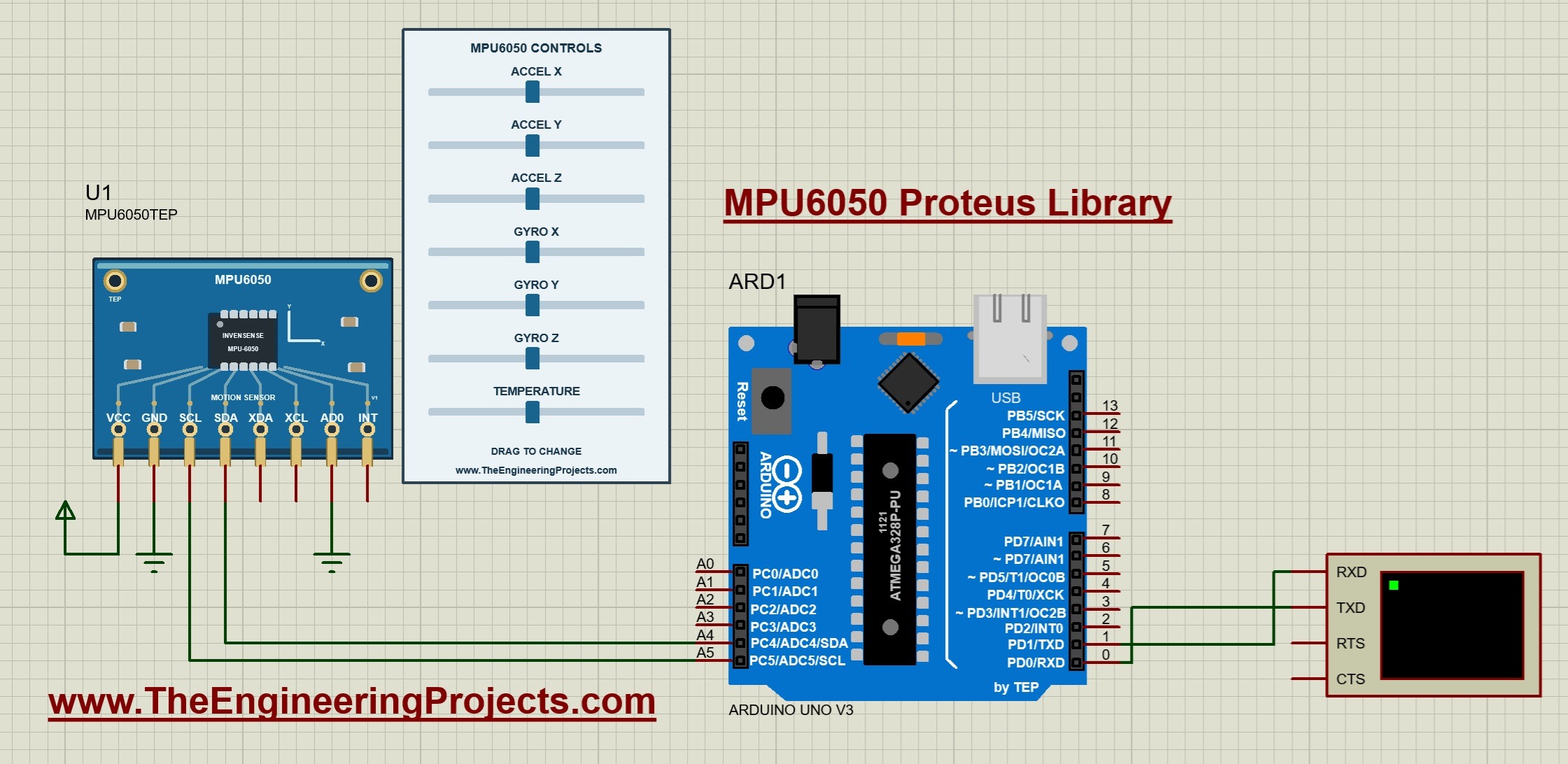
Connect Arduino D1/TX to RXD on the Virtual Terminal. The Arduino transmits the printed readings and the terminal receives them. The circuit also shows terminal TXD connected to Arduino D0/RX, although this sketch does not require incoming serial commands.
Set the terminal to 9600 baud, eight data bits, no parity and one stop bit. These settings must agree with the program. Also confirm that the Uno clock is 16 MHz, because a clock mismatch affects firmware timing and serial communication.
The example uses the AVR Wire implementation's internal pull-ups in this digital simulation. When building physical hardware, check your actual module's supply, logic levels and external pull-up requirements. The model does not simulate a breakout board's regulator or establish voltage compatibility for every board sold as an MPU6050 module.
Run the MPU6050 Simulation
We are now ready to start. Open Proteus Simulation/MPU6050-ArduinoUnoV3.pdsprj from the extracted package. Keep MPU6050_Demo.hex and TEPMPU6050.DLL in that folder.
- Double-click the Arduino and confirm that its Program File points to MPU6050_Demo.hex.
- Check the 16 MHz clock, 9600 baud terminal and grounded AD0 pin.
- Press Run and open the Virtual Terminal window if it is hidden.
- Read several output lines before changing the controls.
- Move one slider at a time and compare that channel with the corresponding terminal value.
With the documented default properties, expect acceleration near 0.00, 0.00 and 1.00 g; angular velocity near 0.0 degrees per second on each axis; and temperature near 25.0 C. The order is X, Y and Z in both printed groups. If you saved different component properties, those configured values will be used instead.
The running screenshot at the beginning shows acceleration of approximately 7.23, 12.27 and 8.80 g, angular velocity of -1107.0, 1100.0 and -1513.0 degrees per second, and temperature of 58.5 C. These are independently selected simulation inputs. They are not the expected measurements of a stationary board.
Pause briefly after each slider movement. The sketch includes a 500 ms delay and prints two lines per update, so the display does not refresh continuously with the mouse. Older terminal lines remain visible above the latest result and describe the previous inputs.
Using the Seven Sensor Controls
The control panel lets us change the three acceleration channels, three gyroscope channels and temperature independently. Drag a blue handle or click along its track while the simulation is running.
| Control | Input range | Default |
|---|---|---|
| ACCEL X and ACCEL Y | -16 to +16 g | 0 g each |
| ACCEL Z | -16 to +16 g | 1 g |
| GYRO X, GYRO Y and GYRO Z | -2000 to +2000 degrees per second | 0 each |
| TEMPERATURE | -40 to +85 C | 25 C |
Acceleration inputs include the gravity contribution. The model does not calculate the motion of a rotating three-dimensional object and automatically redistribute gravity between axes. If you want to represent a particular resting orientation, enter a suitable combination of acceleration values yourself.
For exact initial values, stop the simulation and edit AX, AY, AZ, GX, GY, GZ and TEMPERATURE in the sensor properties. Restarting restores those configured values. Dragging a handle changes the input during the current run rather than permanently rewriting the saved starting property.
The read-only NAME, VERSION and Designed by fields identify the library. They are separate from the adjustable inputs. The ranges in the table describe the panel; the measurement range selected by your firmware determines how those inputs fit into the returned digital values.
Arduino Code for the MPU6050 Simulation
The following sketch is the one included in the ZIP. It uses the Adafruit MPU6050 library to initialize the device and obtain sensor events. The package contains version 2.2.9 of that driver, its dependencies and the sources needed to reproduce the supplied firmware.
#include <Wire.h>
#include <Adafruit_MPU6050.h>
Adafruit_MPU6050 sensor;
bool ready=false;
void setup() {
  Serial.begin(9600); Wire.begin(); Wire.setWireTimeout(25000,true);
  ready=sensor.begin(0x68);
  if(!ready) { Serial.println(F("MPU6050 not found. Check power, A4/SDA, A5/SCL and AD0.")); return; }
  sensor.setAccelerometerRange(MPU6050_RANGE_16_G);
  sensor.setGyroRange(MPU6050_RANGE_2000_DEG);
  sensor.setFilterBandwidth(MPU6050_BAND_21_HZ);
  Serial.println(F("TEP MPU6050 - drag acceleration, gyro and temperature controls."));
}
void loop() {
  if(ready) {
    sensors_event_t a,g,t; sensor.getEvent(&a,&g,&t);
    Serial.print(F("Accel g: ")); Serial.print(a.acceleration.x/9.80665,2);
    Serial.print(F(", ")); Serial.print(a.acceleration.y/9.80665,2);
    Serial.print(F(", ")); Serial.println(a.acceleration.z/9.80665,2);
    Serial.print(F("Gyro deg/s: ")); Serial.print(g.gyro.x*57.29578,1);
    Serial.print(F(", ")); Serial.print(g.gyro.y*57.29578,1);
    Serial.print(F(", ")); Serial.print(g.gyro.z*57.29578,1);
    Serial.print(F(" | T: ")); Serial.print(t.temperature,1); Serial.println(F(" C"));
  }
  delay(500);
}
Initialize the Sensor and Select Its Ranges
In setup, Serial.begin opens the serial port at 9600 baud and Wire.begin starts I2C. The Wire timeout is 25,000 microseconds, or 25 ms, with bus reset enabled after a timeout. The call sensor.begin(0x68) uses the address selected by grounding AD0.
The variable ready records whether initialization succeeded. If it fails, the program prints the connections to check and does not request normal readings. After correcting a connection, restart the simulation so setup runs again; this example does not repeatedly attempt initialization inside loop.
The next two calls select the widest available ranges: ±16 g and ±2000 degrees per second. These match the panel's full input spans. A smaller range gives more digital counts per unit, but large inputs will saturate sooner.
The sketch also selects the 21 Hz filter setting. This model stores the filter configuration and uses it in its sampling-timing behavior, but it does not reproduce the physical digital filter's smoothing response. Do not use the slider response to measure the real chip's filter frequency response.
Read the Events and Convert the Display Units
The call sensor.getEvent(&a, &g, &t) fills the acceleration, gyroscope and temperature events. Adafruit's Arduino guide demonstrates the same event interface: acceleration is expressed in meters per second squared and angular velocity in radians per second. Our sketch converts those units to match the panel.
Acceleration in g = acceleration in meters per second squared / 9.80665
Angular velocity in degrees per second = angular velocity in radians per second × 180 / pi
The code uses 57.29578 for the second conversion factor. For example, 19.6133 meters per second squared becomes 2 g, and approximately 1.570796 radians per second becomes 90 degrees per second. Temperature is already returned in Celsius and needs no extra conversion.
Acceleration is printed with two decimal places; gyroscope and temperature use one. These are formatting choices rather than accuracy claims. The supplied sketch is intentionally simple: its ready flag checks startup, not every later bus transaction. More demanding firmware should add communication-error handling appropriate to the driver.
Understanding Raw Measurements and Scaling
Inside the interface, each acceleration, gyroscope and temperature measurement uses a signed 16-bit value. Two bytes must be combined in the correct order and interpreted as signed. Treating a negative measurement as an unsigned integer produces a large positive number instead.
| Acceleration range | Counts per g | Gyroscope range | Counts per degree per second |
|---|---|---|---|
| ±2 g | 16384 | ±250 degrees per second | 131 |
| ±4 g | 8192 | ±500 degrees per second | 65.5 |
| ±8 g | 4096 | ±1000 degrees per second | 32.8 |
| ±16 g | 2048 | ±2000 degrees per second | 16.4 |
For our configured ranges, acceleration in g = signed raw value / 2048, while angular velocity in degrees per second = signed raw value / 16.4. A raw acceleration count of 2048 therefore represents 1 g. A raw gyroscope count of 1640 represents 100 degrees per second.
The Adafruit driver performs the register decoding and scaling before returning its events. These formulas explain its work; do not divide the event values by 2048 or 16.4 again. Apply only the unit conversions used by the supplied sketch.
The temperature relationship is temperature in C = signed temperature count / 340 + 36.53, as implemented in the Adafruit MPU6050 driver source. A count of -3920 corresponds to approximately 25.0006 C, which displays as 25.0 C. This is an internal sensor-temperature reading, not a precision ambient thermometer.
The panel input is converted to integer counts, so rounding and clipping can create small differences. At the positive gyroscope endpoint, 2000 × 16.4 gives 32800, which exceeds the largest signed 16-bit value of 32767. This model therefore returns approximately 32767 / 16.4, or 1998.0 degrees per second. An endpoint difference of this kind is a scaling limit, not necessarily an I2C failure.
Compile the Sketch After Editing It
You can use the supplied HEX for the first demonstration. Once you want different output, additional calculations or an application threshold, edit the source and compile a new binary.
- Open
Arduino Code/MPU6050_Demo/MPU6050_Demo.inoin Arduino IDE. - Select the classic Arduino Uno and the documented Arduino AVR Boards 1.8.6 core.
- Install Adafruit MPU6050, Adafruit BusIO and Adafruit Unified Sensor. For the same source versions as the example, use the folders included under Arduino Code/libraries.
- Compile the sketch and export its application HEX.
- Update the Uno's Program File in Proteus to the new HEX, retain the 16 MHz clock and restart the simulation.
The package also includes a standalone rebuild script and an AVR core source archive. Its README explains the compiler and core directories required for that route. Editing the INO file alone does not update the code already loaded by Proteus.
Useful Experiments with the MPU6050 Library
Start with tests that have a predictable result. Change one input while keeping the others fixed, and compare the expected channel rather than only checking that something moves on screen.
- Set acceleration to 0, 0 and 1 g, with zero angular velocity, to represent the example's resting reference.
- Set X acceleration to +1 g, then -1 g, and confirm that the sign changes in the first acceleration value.
- Set one gyroscope channel to 100 degrees per second and confirm the corresponding output without altering the other axes.
- Change temperature independently and observe its value at the end of the gyroscope line.
- Stop and restart to check that the configured initial properties return.
Estimate a Rotation Increment
For a constant rate, an angle increment is angular velocity × elapsed time. A rate of 90 degrees per second maintained for 0.5 seconds corresponds to 45 degrees. If you extend the sketch to integrate rotation, measure the actual interval between samples instead of assuming every loop lasts exactly 500 ms.
The delay, printing and other instructions all contribute to loop time. A real gyroscope also has bias and noise, so integrated angle drifts. The deterministic simulation is useful for checking your arithmetic and sign conventions, but it does not reproduce those physical error sources.
Check a Stationary Acceleration Vector
For a gravity-only example, the vector magnitude should be about 1 g. Calculate magnitude = sqrt(AX squared + AY squared + AZ squared). With 0, 0 and 1 g, the result is 1 g. With 0, 0.6 and 0.8 g, it is also 1 g because 0.36 + 0.64 = 1.
This gives you a consistent input for later tilt exercises. The model permits arbitrary combinations, including the large values in the featured screenshot. A program should not interpret every arbitrary slider combination as a stationary orientation or an absolute heading.
Common Problems and Their Solutions
| Problem | What to check |
|---|---|
| MPU6050TEP is missing from Pick Devices. | Confirm that TEPMPU6050.LIB is in the active library path and restart Proteus. Search for the exact device name. |
| The sensor appears but its model cannot load. | Check TEPMPU6050.DLL in MODELS and beside the supplied project. |
| The terminal is blank. | Check Run, the HEX path, the 16 MHz clock and Arduino D1/TX to terminal RXD. |
| The terminal prints unreadable characters. | Use 9600 baud and the specified serial format; verify the Uno clock. |
| The sketch reports MPU6050 not found. | Check power, common ground, SDA/A4, SCL/A5 and AD0/GND. Restart after correcting the circuit. |
| Readings stop increasing before the slider endpoint. | Check the firmware range and signed-count saturation. A narrow configured range cannot represent the entire slider span. |
| Your changes to the sketch do not appear. | Compile again and select the new HEX in the Arduino properties. |
| A gyroscope value is mistaken for an angle. | Read the unit: degrees per second is angular velocity. Calculating an angle requires time integration or a suitable estimator. |
If the circuit behaves unexpectedly, return to the supplied project and test one change at a time. Include your Proteus version, the selected address and a screenshot of the circuit and terminal when asking for help.
Practical Review and Model Limitations
This library is useful for practicing I2C initialization, signed data handling, measurement ranges, unit conversion and Arduino display logic. Its independent inputs make it easy to reproduce a test condition, and the included code provides a clear starting point for your own experiments.
The model implements acceleration, gyroscope and temperature registers, range selection, sampling configuration, sleep, reset and FIFO behavior. The supplied sketch uses ordinary event reads rather than a FIFO application. DMP firmware, auxiliary I2C master operation, self-test calibration, motion detection and offset calibration are outside this version's scope.
It also does not simulate physical digital-filter dynamics, mechanical motion, random sensor noise or board-level analog behavior. Keep those limits in mind when moving an application to hardware. A working simulated register exchange checks your firmware path; physical calibration and measurement performance require a real sensor.
Frequently Asked Questions
Can I Use a Different Microcontroller?
A different controller needs its own compatible I2C firmware and pin assignments. The supplied HEX targets the Uno's ATmega328P; it cannot be loaded into an unrelated processor. First reproduce the Uno example, then check your adapted circuit separately.
Why Does Z Acceleration Start at 1 g?
The documented default represents gravity along the Z axis for the example's resting orientation. Zero gyroscope readings mean no rotation; they do not require all accelerometer channels to be zero.
Can I Use the Address 0x69?
The model supports 0x69 when AD0 is high. Change both the AD0 connection and the address passed to sensor.begin. The included circuit and sketch use AD0 low and 0x68.
Do I Need to Connect XDA, XCL or INT?
Leave them unconnected for this example. XDA and XCL are unimplemented auxiliary connections in this model, and the polling sketch does not require INT.
Can This Library Provide DMP Quaternions or Compass Heading?
DMP firmware is not implemented, and the MPU6050 has no magnetometer channel in this model. The supplied example prints acceleration and angular velocity; it does not directly provide absolute orientation or a compass heading.
Do I Need Arduino IDE to Run the Supplied Circuit?
No. The package includes the compiled Uno HEX. Arduino IDE or the documented build tools are needed when you edit the sketch and want to generate replacement firmware.
That completes our MPU6050 Proteus Library tutorial. Install the files, check the connections and run the supplied example before expanding the project. Try the single-axis and unit-conversion exercises, then share your results or questions in the comments.
Comments
0