


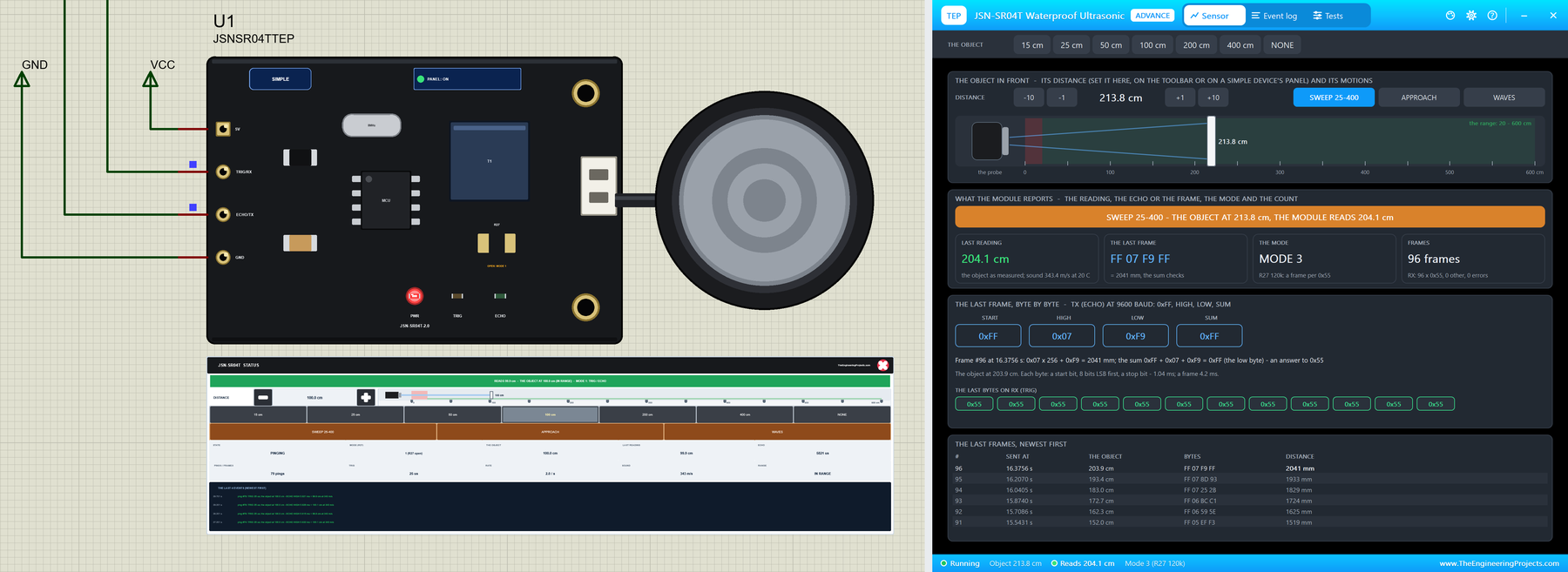
JSN-SR04T Waterproof Ultrasonic Sensor Library for Proteus V1.0


Hello friends, I hope you all are doing great. Today, I am going to share the new JSN-SR04T Waterproof Ultrasonic Sensor Library for Proteus V1.0. The JSN-SR04T is the waterproof cousin of the HC-SR04: a small driver board and a sealed probe on a long cable, so it can measure the water in a tank, the distance to a car in a garage or the ground under an outdoor robot, from about 20 to 600 cm. Now you can test those projects in Proteus.
Behind the part sits our own model, not a delay with a number. It has all three modes of the board, set by the R27 pad: trigger and echo like the HC-SR04, a serial frame every 100 ms, and a serial frame each time you send 0x55. It times the echo with the speed of sound at the air temperature, has the probe's blind zone, and reports no echo the way the module does. You move the object, pick a preset, or run a sweep, an approach or a water surface with waves. You get two devices: a Simple device with a live STATUS panel and an Advance device with a pop-up window and the test tools. The demo runs on our Arduino UNO V4.0.
NOTICE: an ultrasonic sensor is easy to fake: a pulse as long as the distance. We wanted more. Our JSN-SR04T has the real board's three modes and its serial frames, so a sketch that pings too fast, asks again too soon or reads the wrong mode fails exactly as it does with the real module. It took our team a lot of hard work. Your feedback is the fuel that keeps us going, so please tell us what you think in the comments below or in the JSN-SR04T board of our forum. And if our free libraries help you, you can buy us a coffee. So, let's get started with the JSN-SR04T Waterproof Ultrasonic Sensor Library for Proteus V1.0:
What is the JSN-SR04T?
The JSN-SR04T is an ultrasonic distance module made of two parts: a driver board with a 4-pin header, and a waterproof probe at the end of a cable. The probe is one sealed transducer that both sends the burst of sound and listens for its echo, so it can sit outside, in the rain or above water. It measures the same way as the HC-SR04 - see our Introduction to HC-SR04 Ultrasonic Sensor and our Ultrasonic Sensor Library for Proteus - but it has more ways to give you the result.
| JSN-SR04T | |
|---|---|
| Range | about 20 (25) to 600 cm |
| Supply | 3.0 to 5.5 V |
| Pins | 5V, TRIG (RX), ECHO (TX), GND |
| Modes (R27) | open: trigger / echo; 47k: a frame every 100 ms; 120k: a frame for each 0x55 |
| Serial | 9600 baud, 8N1; frame 0xFF, high byte, low byte, sum - the distance in mm |
| Probe | one waterproof transducer on a cable |
| Devices | JSNSR04TTEP (Simple) and JSNSR04TADVTEP (Advance) |
How It Measures
A ping starts with a short burst of ultrasound from the probe. The sound travels to the object, bounces back, and the same probe hears the echo. The module measures the time in between, and the distance is half of that time multiplied by the speed of sound: about 58 us per centimetre at 20 C, so 100 cm gives a round trip of 5.82 ms and 600 cm about 35 ms. Sound is faster in warm air - 331.3 + 0.606 x T m/s - which is why the model has an air temperature.
The Three Modes
| R27 | Mode | What the module does |
|---|---|---|
| open | 1: trigger / echo | a 10 us HIGH pulse on TRIG starts a ping; ECHO is HIGH for the round trip |
| 47k | 2: serial, automatic | a frame on TX (the ECHO pin) every 100 ms, by itself |
| 120k | 3: serial, on request | a frame on TX each time it receives 0x55 on RX (the TRIG pin) |
In modes 2 and 3 the two middle pins become a serial port at 9600 baud. A frame has four bytes: 0xFF, the distance's high byte, its low byte, and the low 8 bits of the sum of the first three. The distance is in millimetres, so FF 03 E8 EA means 0x03E8 = 1000 mm, and 0xFF + 0x03 + 0xE8 = 0x1EA, whose low byte is 0xEA.
The Blind Zone
With one transducer for both jobs, the probe still rings for a moment after the burst, and it cannot hear an echo that comes back during that time. Our model listens only after 1.2 ms: an object closer than about 20 cm reads about 21 cm, whatever its real distance. With nothing in front, or beyond 600 cm, there is no echo: ECHO stays HIGH for 36 ms in mode 1, and the frames carry 0 mm.
What's New in JSN-SR04T Waterproof Ultrasonic Sensor Library for Proteus V1.0
- The real module: the black driver board with its header, MCU, drive transformer, crystal, the R27 pad and the probe's socket, and the round waterproof probe on its cable. The board draws R27's value and the mode next to the pad.
- Two styles: a Simple device with a STATUS panel and an Advance device with a pop-up window; the PWR, TRIG and ECHO LEDs and the panel button sit on the board.
- All three modes: trigger / echo, a frame every 100 ms, and a frame for each 0x55, at 9600 baud with the checksum.
- The physics: the round trip at the speed of sound for the air temperature, the 1.2 ms blind zone, no echo beyond 600 cm, one ping per 50 ms, and the noise of each reading.
- The object on the panel: its distance in 5 cm steps, seven presets (15, 25, 50, 100, 200, 400 cm and NONE) and three motions: SWEEP 25-400, APPROACH and WAVES (a water surface).
- The mistakes caught: a TRIG pulse under 10 us, pings too fast, TRIG held HIGH, pings sent to a serial board, a wrong byte or a 0x55 too soon in mode 3, framing errors.
- Three test tools on the Advance device: Ping timing, Serial frames, and Range & blind zone.
- A two-node demo on our Arduino UNO V4.0: one sketch for all modes - pulseIn() in mode 1, AltSoftSerial in modes 2 and 3 - with RAW and the air temperature.
- A compact package: about 1.25 MB, without the C++ source code of the model.
Two Devices: Simple and Advance
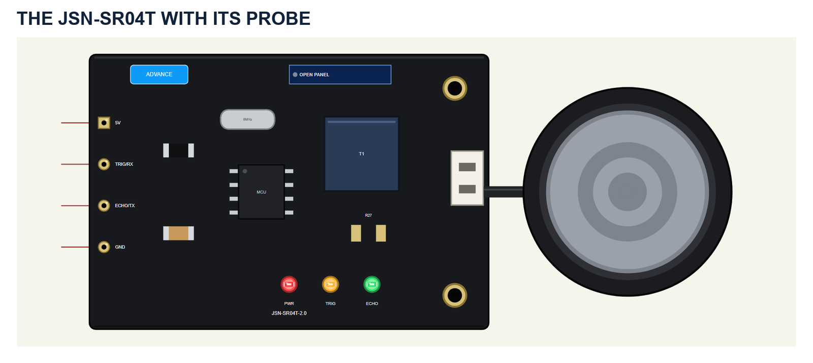
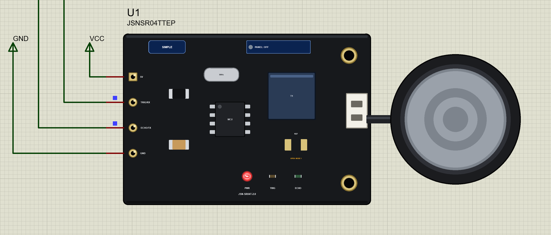
On the left is the 4-pin header with its silk labels 5V, TRIG/RX, ECHO/TX and GND; these are the part's pins. The board carries the MCU, the transformer that drives the probe, the crystal, and the R27 pad, empty for mode 1. The round waterproof probe sits at the end of its cable on the right.
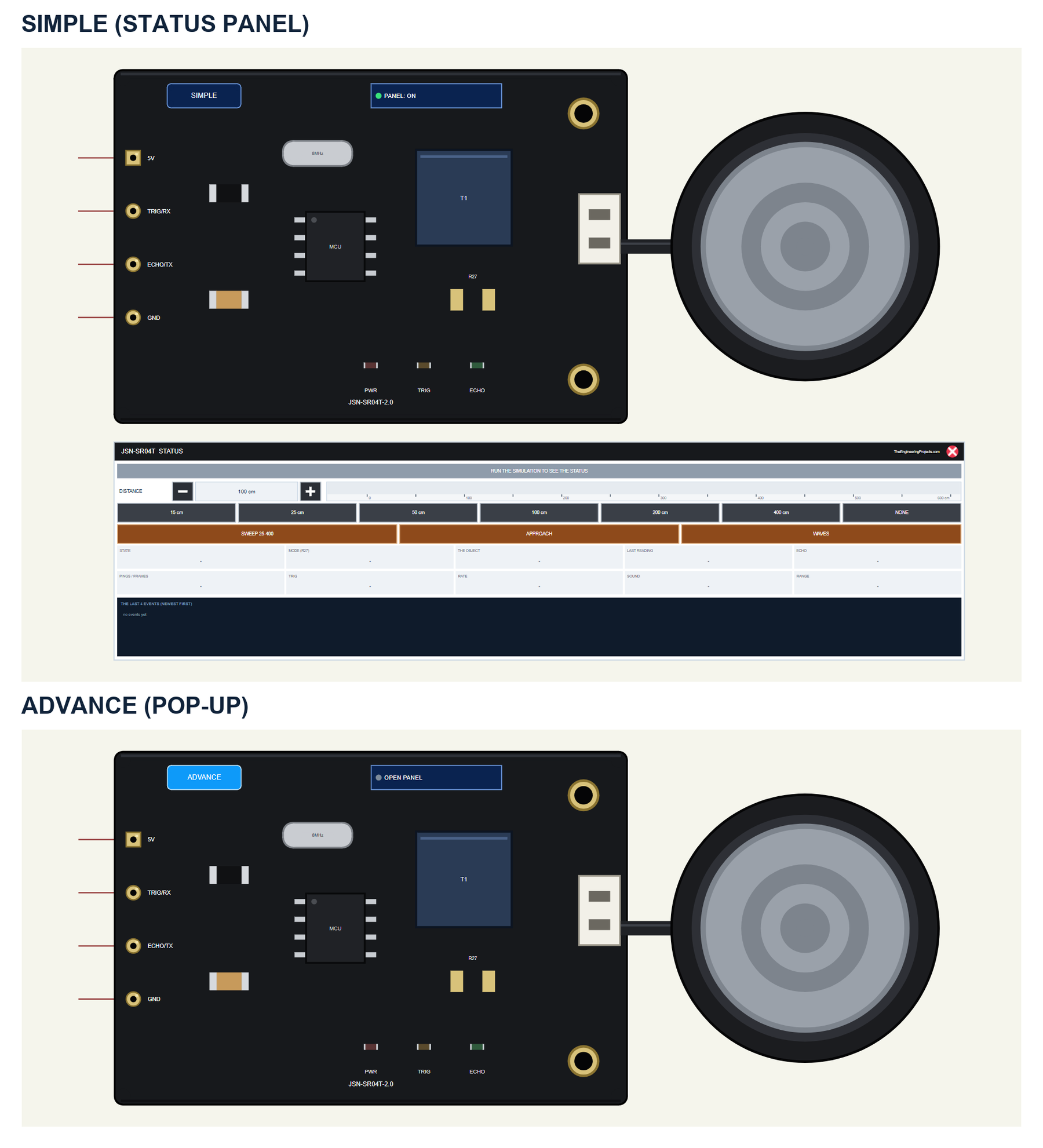
| Simple | Advance | |
|---|---|---|
| Device | JSNSR04TTEP | JSNSR04TADVTEP |
| On the schematic | The module and the STATUS panel | The module |
| The object and its motions | On the STATUS panel | In the pop-up |
| Status | Banner, a ruler, 10 readouts, the last 4 events | A pop-up: Sensor, Event log, Tests |
Download JSN-SR04T Waterproof Ultrasonic Sensor Library for Proteus
Click the button below to download JSN-SR04T-Waterproof-Ultrasonic-Library-for-Proteus-v1.0.zip (about 1.25 MB, without the C++ source code of the model):
JSN-SR04T Waterproof Ultrasonic Sensor Library for Proteus V1.0- README.txt: the devices, installation, the demo, wiring, the test tools and real hardware.
- Proteus Library Files:
TEPJSNSR04T.LIBandArduinoV4TEP.LIBfrom our Arduino Library for Proteus V4.0. - Proteus Model Files:
TEPJSNSR04T.DLLandTEPARDUINO.DLL. - Proteus Simulation:
JSN-SR04T-Ultrasonic-ArduinoUnoV4.pdsprj,JSNSR04T_Distance_Demo.hexand copies of the two DLLs. - Arduino Code:
JSNSR04T_Distance_Demo.ino- it needs AltSoftSerial from the Library Manager to rebuild it.
No Proteus yet? Read How to Download and Install Proteus 7 and 8. New to libraries? Follow How to Install a New Library in Proteus.
How to Install JSN-SR04T Waterproof Ultrasonic Sensor Library for Proteus
- Close Proteus and extract the whole zip file, for example to your Desktop.
- Copy the two files from Proteus Library Files into the LIBRARY folder of Proteus (usually
C:\Program Files (x86)\Labcenter Electronics\Proteus 8 Professional\LIBRARY). - Copy
TEPJSNSR04T.DLLandTEPARDUINO.DLLfrom Proteus Model Files into the MODELS folder. - Delete
TEPJSNSR04T.IDXfrom the LIBRARY folder if it is there. - Start Proteus, press P and search for JSN or SR04T.
Tip: keep the Proteus Simulation folder together, because the project needs its .hex file and the DLLs beside it. The library is tested in Proteus 8.5; Proteus 7 is not supported.
The JSN-SR04T Parts in Proteus
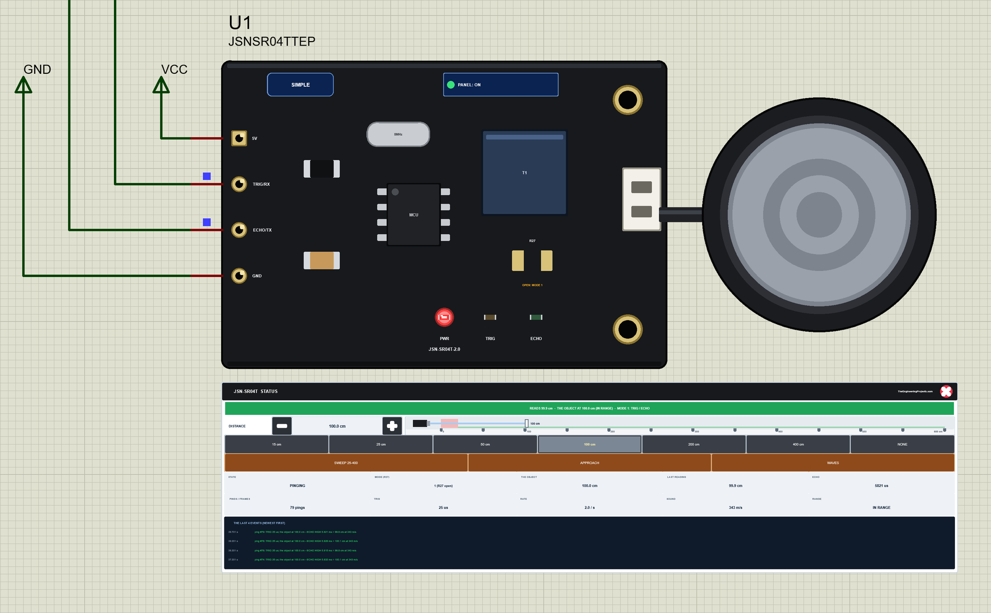
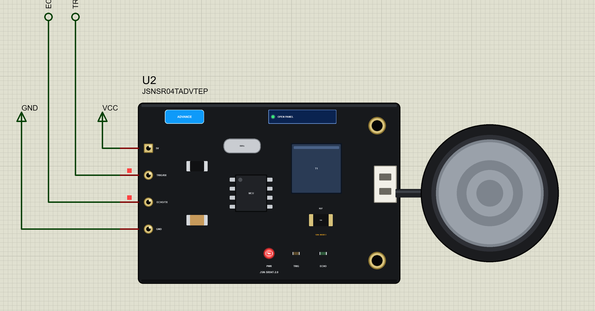
Three LEDs sit on the board: PWR while the module has power, TRIG for the pings or the bytes on RX, and ECHO for the echo pulses or the frames on TX. Under the R27 pad the board writes the mode: OPEN: MODE 1 here; with the MODE property at 2 or 3 the pad gets a 47k or 120k resistor. The LEDs, the badge, the button and the panels are TEP additions; the real board has none of them.
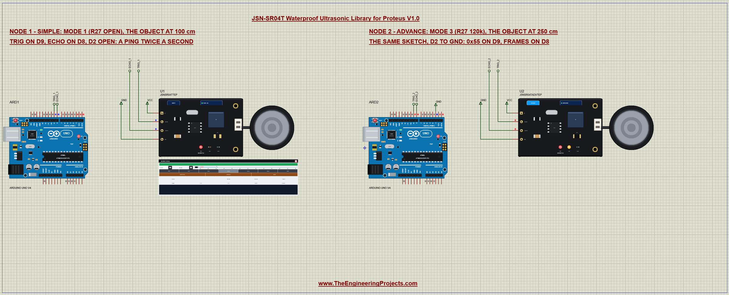
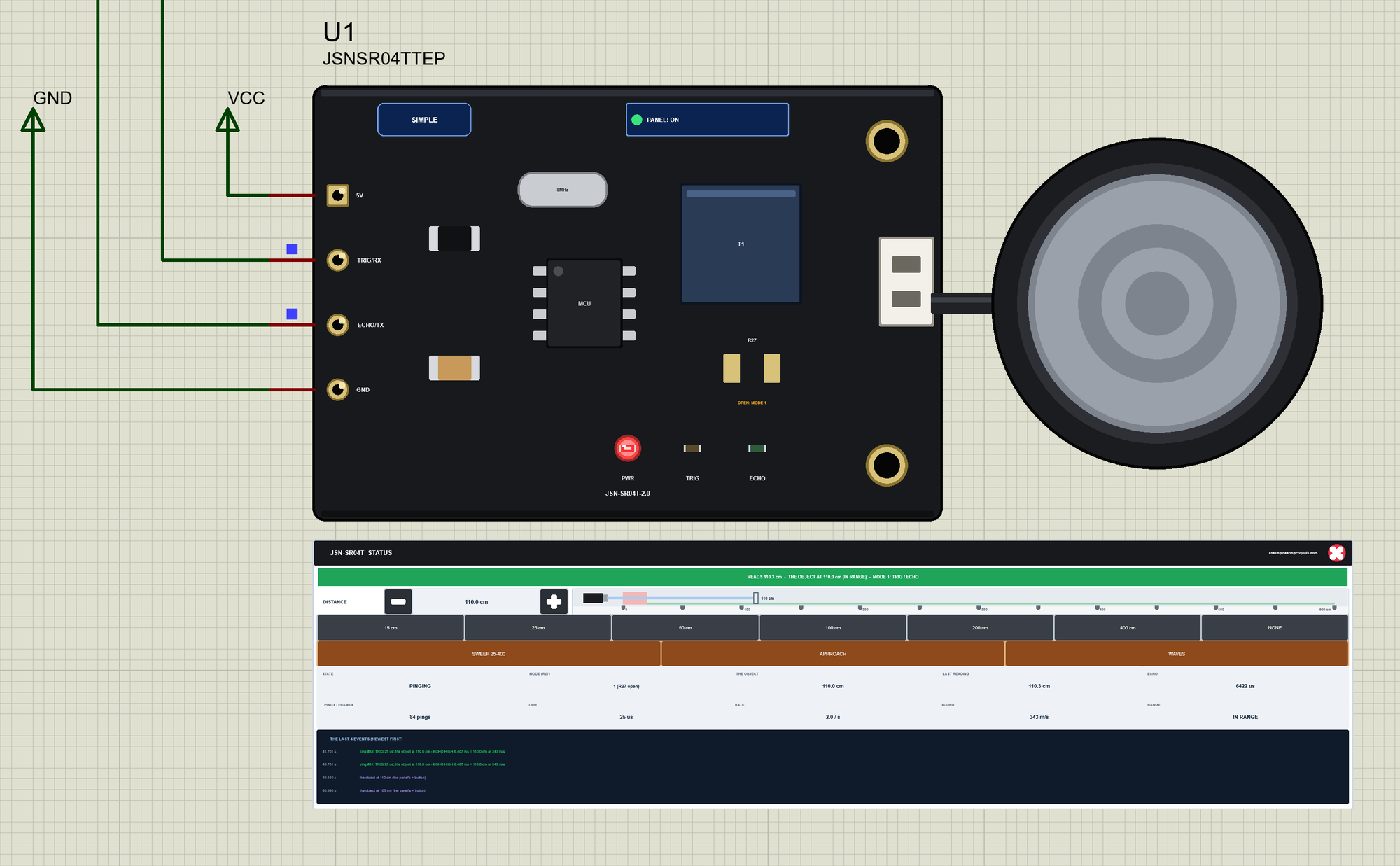
The Simple device adds the STATUS panel. Its banner shows what the module reads and where the object really is; it turns amber while the object moves or nothing echoes, and red in the blind zone. Below it are the controls: DISTANCE with - and + (5 cm a click) and a ruler from 0 to 600 cm with the blind zone shaded; seven presets; and three motions - SWEEP 25-400, APPROACH and WAVES. Ten readouts follow - the state, the mode, the object, the last reading, the echo, the pings or frames, the TRIG pulse, the rate, the speed of sound and the range - and the last four events.
The red X closes the STATUS panel, and the PANEL button on the board opens it again:
The Advance device keeps the schematic clean: only the module. Its live data opens in a pop-up window at Run, and the OPEN PANEL button on the board brings the window back. The properties set the start: DISTANCE (the object in cm, 0 for nothing in front), MODE (1, 2 or 3), TEMP (the air, 20 C) and NOISE (3 mm RMS).
The Demo Circuit
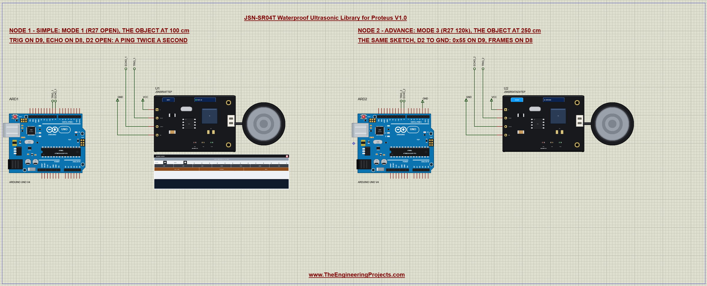
The demo project has two nodes, each an Arduino UNO V4.0 from our Arduino UNO Library for Proteus V4.0 with a JSN-SR04T. On both, TRIG goes to D9 and ECHO to D8. Node 1 is in mode 1 with the object at 100 cm. Node 2 is in mode 3 with the object at 250 cm, and its D2 goes to GND, which tells the sketch to use the serial modes. Both UNOs run the same JSNSR04T_Distance_Demo.hex.
Wiring
| Module | Arduino UNO |
|---|---|
| 5V | 5V |
| TRIG / RX | D9 |
| ECHO / TX | D8 |
| GND | GND |
| - | D2: open = mode 1, to GND = serial |
Why D8 and D9? In mode 1 any two pins would do, but the serial modes need a second serial port, and on the UNO AltSoftSerial always uses D8 to receive and D9 to send. So the demo uses those two pins for every mode. In Proteus, TRIG and ECHO reach their UNO through net labels, TRIG_1 and ECHO_1 for node 1 and TRIG_2 and ECHO_2 for node 2. The serial monitor needs no wires at all, because it is built into the UNO V4.0.
The Arduino Code
The demo sketch reads all three modes. New to Arduino? Start with Arduino Tutorial for Beginners and Introduction to Arduino UNO; the classic mode 1 code is the same as in Ultrasonic Sensor Arduino Interfacing. For the serial modes it uses AltSoftSerial by Paul Stoffregen, a software serial port on D8 and D9 that keeps exact timing (see also How to use Arduino Software Serial and our HC-12 Library for Proteus, which uses it too):
#include <AltSoftSerial.h>const uint8_t TRIG_PIN = 9, ECHO_PIN = 8, MODE_PIN = 2;
const unsigned long NO_ECHO_US = 35500; // the module holds ECHO HIGH about 36 ms when no echo comes backAt the start the sketch reads D2: open means mode 1, LOW means a serial mode.
serialMode = digitalRead(MODE_PIN) == LOW;Mode 1: a Ping and pulseIn()
A ping is a 20 us HIGH pulse on TRIG; pulseIn() then times ECHO. The function first waits until 60 ms have passed since the last ping, because the module ignores a TRIG within 50 ms of its last one:
unsigned long ping() {
  while (millis() - lastPing < 60) {}            // the module ignores a TRIG within 50 ms of the last ping
  digitalWrite(TRIG_PIN, LOW);
  delayMicroseconds(4);
  digitalWrite(TRIG_PIN, HIGH);
  delayMicroseconds(20);                         // 10 us or more
  digitalWrite(TRIG_PIN, LOW);
  unsigned long us = pulseIn(ECHO_PIN, HIGH, 60000UL);
  lastPing = millis();
  return us;
}
The distance is the round trip times the speed of sound, halved. The speed depends on the air temperature, which the TEMP command sets:
float soundSpeed() {                             // m/s
  return 331.3 + 0.606 * airC;
}
float cmOf(unsigned long us) { // the round trip, halved
return us * soundSpeed() / 20000.0;
}Anything above 35.5 ms is the module saying "no echo".
Modes 2 and 3: the Frames
In the serial modes the sketch keeps the last four bytes it received and accepts them as a frame when they start with 0xFF and the sum checks:
    if (nWin < 4 || win[0] != 0xFF) continue;
    if (uint8_t(win[0] + win[1] + win[2]) != win[3]) { sumErrors++; continue; }
Mode 3 answers only when asked, so the sketch sends 0x55 whenever no frame came for 150 ms. A board in mode 2 sends every 100 ms by itself and is never quiet that long, so the same code reads both modes:
void askIfQuiet() {                              // mode 3 answers 0x55; mode 2 sends by itself, so it is never quiet
  unsigned long now = millis();
  if (now - lastFrameMs >= 150 && now - lastAskMs >= 150) {
    sonar.write(0x55);
    asks++;
    lastAskMs = now;
  }
}
The HEX file is in the package, so you do not need the Arduino IDE to run the demo. To change the sketch, install AltSoftSerial from the Library Manager and export the compiled binary, as in How to get the HEX file from Arduino. It needs 10,542 bytes of flash and 494 bytes of RAM.
The Serial Monitor
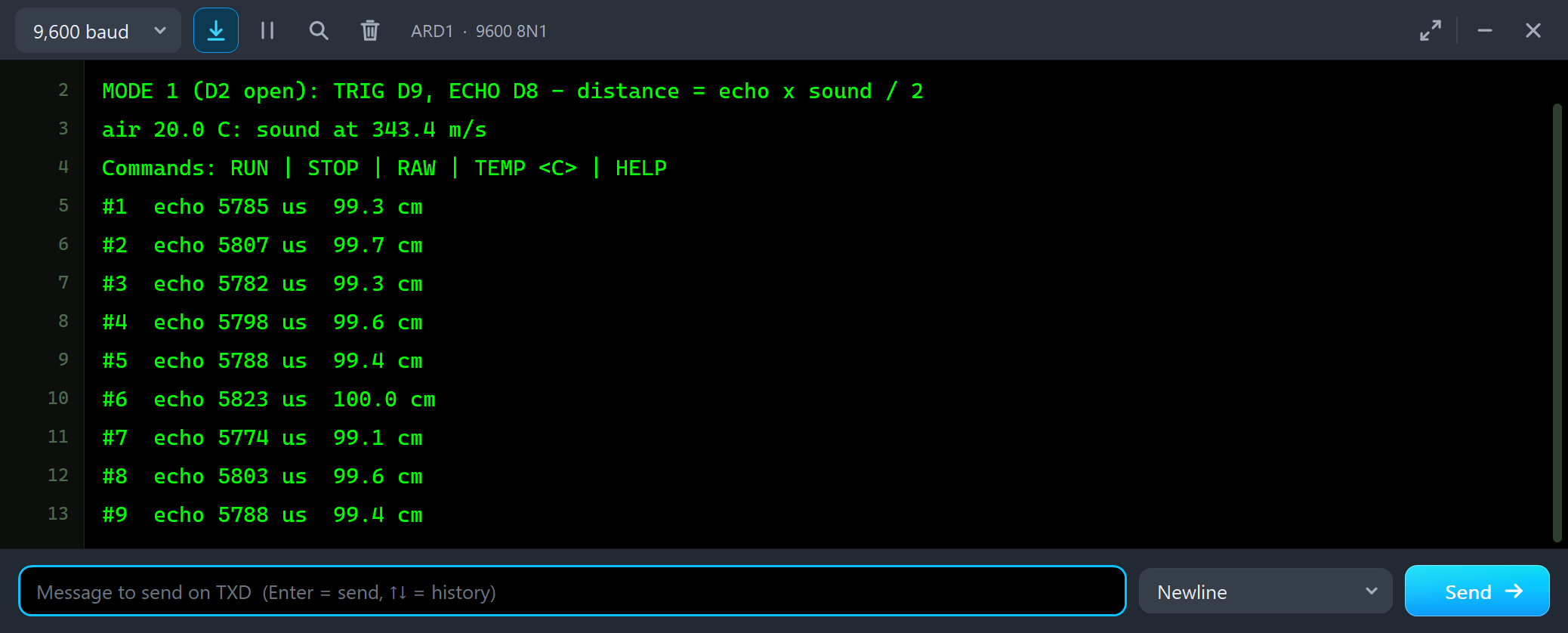
Both UNOs have the serial monitor built in, and it opens at Run. The screenshots use its Simple interface. Node 1, in mode 1, prints the ECHO width and the distance:
MODE 1 (D2 open): TRIG D9, ECHO D8 - distance = echo x sound / 2
air 20.0 C: sound at 343.4 m/s
Commands: RUN | STOP | RAW | TEMP <C> | HELP
#1  echo 5785 us  99.3 cm
#2  echo 5807 us  99.7 cm
#3  echo 5782 us  99.3 cm
#4  echo 5798 us  99.6 cm
#5  echo 5788 us  99.4 cm
#6  echo 5823 us  100.0 cm
ECHO is HIGH for about 5.8 ms, and the sketch prints 99.3 to 100.0 cm for the object at 100 cm; the small changes are the noise of each reading, 3 mm by default. The readings sit a little below 100 cm, and the simulation log shows why: ping #1 had an ECHO pulse of 5.822 ms, but pulseIn() reported 5785 us. It times the pulse by counting the turns of a short loop, which reads about half a percent short. Node 2, in mode 3, prints the four bytes of each frame instead:
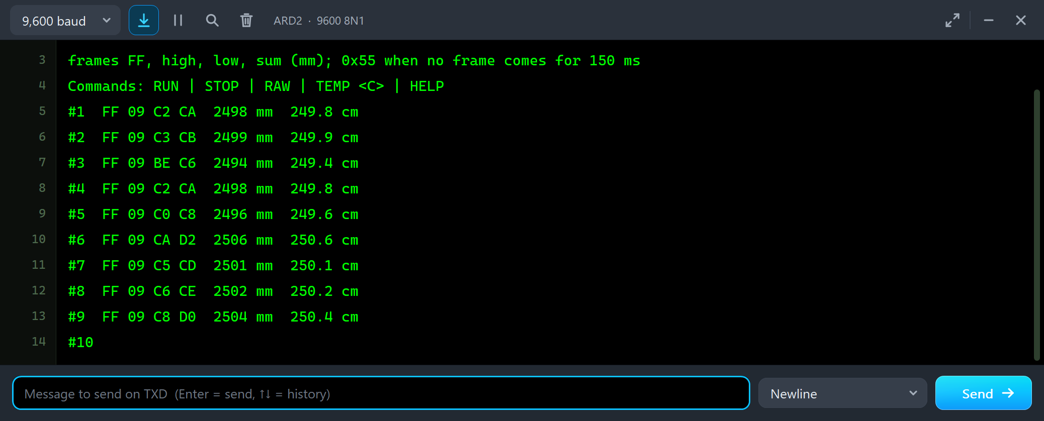
frames FF, high, low, sum (mm); 0x55 when no frame comes for 150 ms
Commands: RUN | STOP | RAW | TEMP <C> | HELP
#1  FF 09 C2 CA  2498 mm  249.8 cm
#2  FF 09 C3 CB  2499 mm  249.9 cm
#3  FF 09 BE C6  2494 mm  249.4 cm
#4  FF 09 C2 CA  2498 mm  249.8 cm
#5  FF 09 C0 C8  2496 mm  249.6 cm
The sketch sends 0x55, gets a frame back, and asks again 150 ms after it: about six frames a second, two of them printed. FF 09 C2 CA is 0x09C2 = 2498 mm, and 0xFF + 0x09 + 0xC2 = 0x1CA, so the sum byte is 0xCA. The module converts the time to millimetres by itself, so there is no pulseIn() error here: 249.4 to 249.9 cm for the object at 250 cm.
Move the Object on the STATUS Panel
Now let's move node 1's object while the simulation runs. We clicked the + button of U1's panel twice with the mouse:
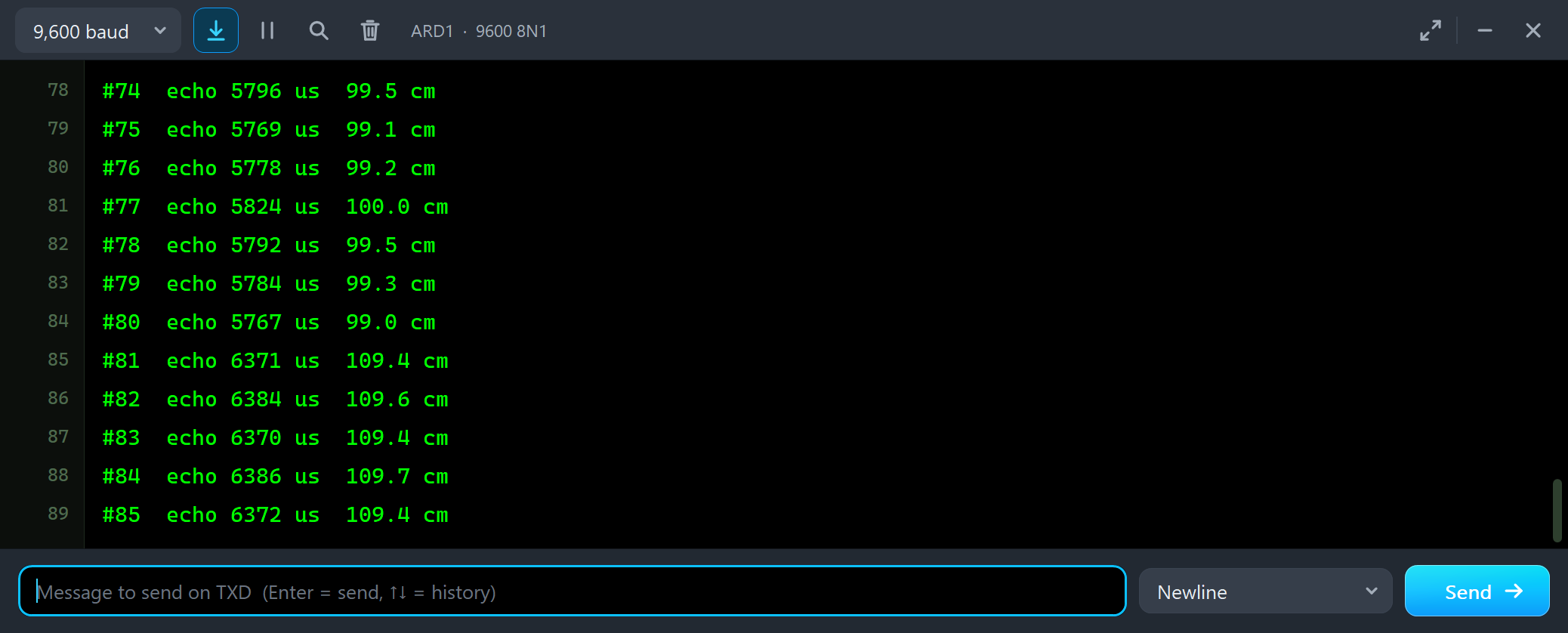
#78  echo 5792 us  99.5 cm
#79  echo 5784 us  99.3 cm
#80  echo 5767 us  99.0 cm
#81  echo 6371 us  109.4 cm
#82  echo 6384 us  109.6 cm
#83  echo 6370 us  109.4 cm
#84  echo 6386 us  109.7 cm
The reading follows on the next line: 109.4 to 109.7 cm for the object at 110 cm. Ten centimetres more is about 0.58 ms more of round trip - here from about 5.78 to about 6.37 ms.
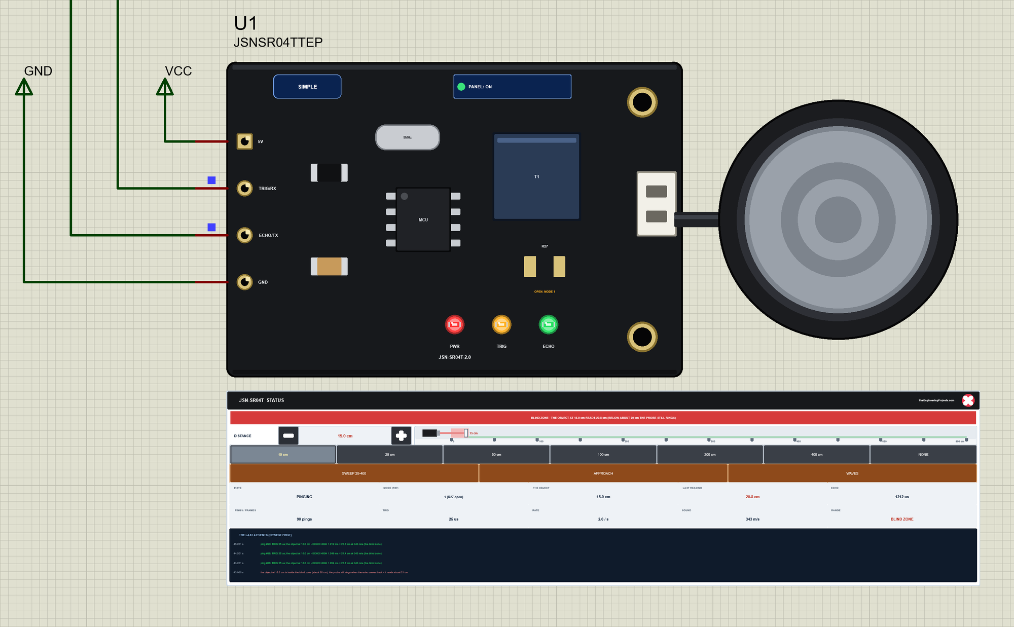
15 cm: the Blind Zone
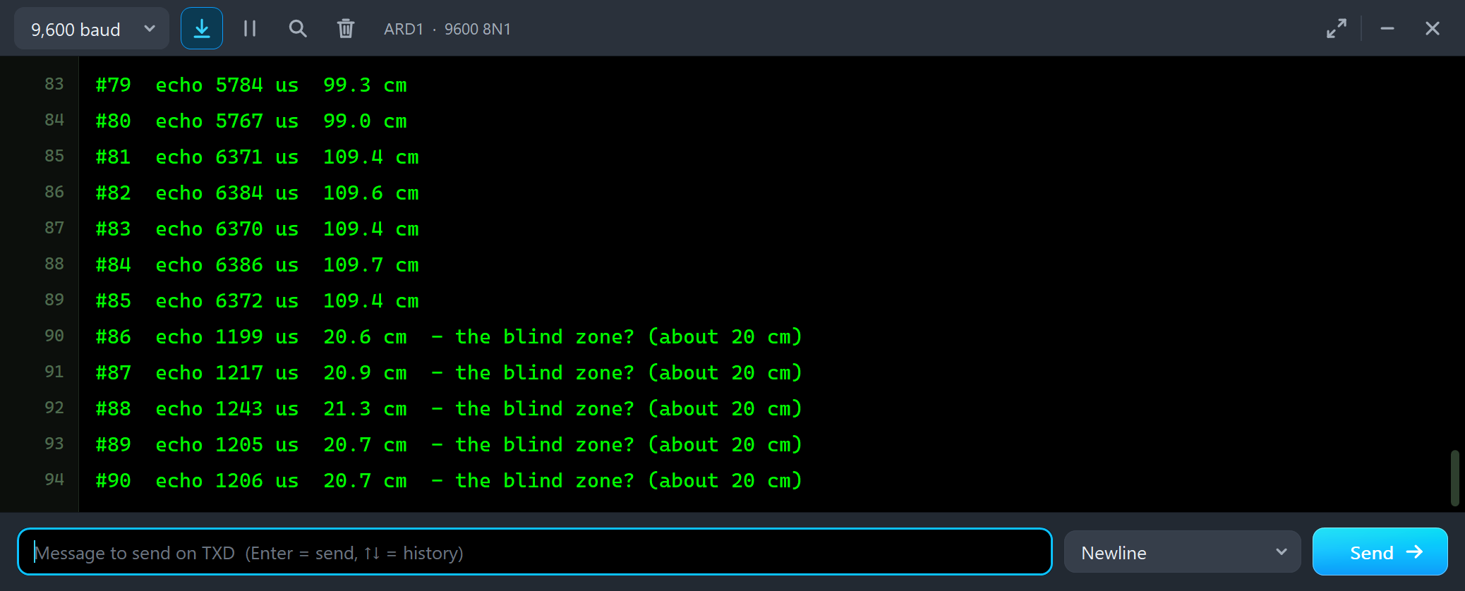
#84  echo 6386 us  109.7 cm
#85  echo 6372 us  109.4 cm
#86  echo 1199 us  20.6 cm  - the blind zone? (about 20 cm)
#87  echo 1217 us  20.9 cm  - the blind zone? (about 20 cm)
#88  echo 1243 us  21.3 cm  - the blind zone? (about 20 cm)
#89  echo 1205 us  20.7 cm  - the blind zone? (about 20 cm)
#90  echo 1206 us  20.7 cm  - the blind zone? (about 20 cm)
The object is at 15 cm, but ECHO stays HIGH for about 1.2 ms, and the sketch prints 20.6 to 21.3 cm. That is the blind zone: the probe is still ringing from its own burst and listens only after 1.2 ms, so a closer echo is lost and the module reports about 21 cm. The sketch marks readings under 22 cm with a question mark, because it cannot know whether the object is really there or closer.
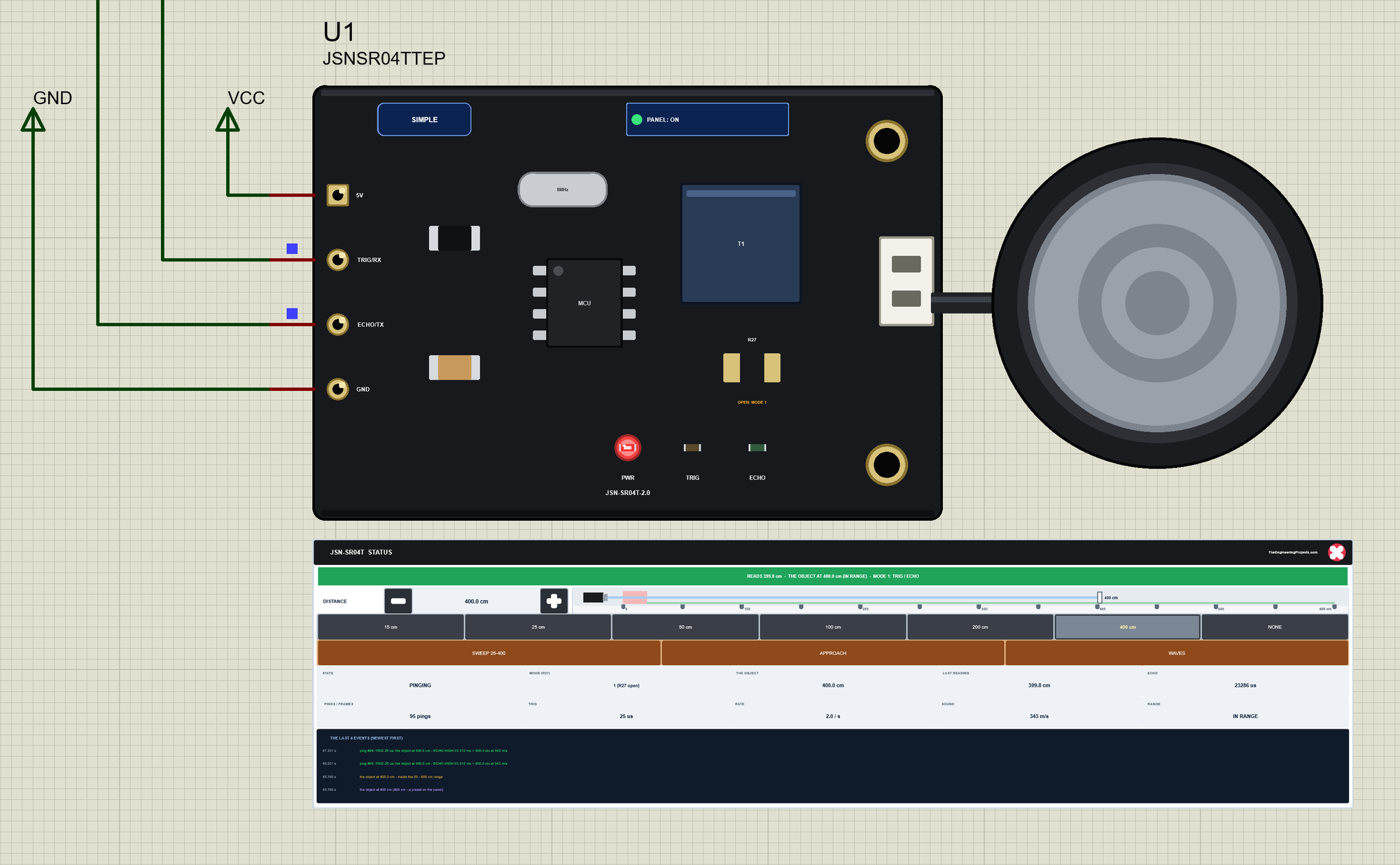
400 cm and Nothing in Front
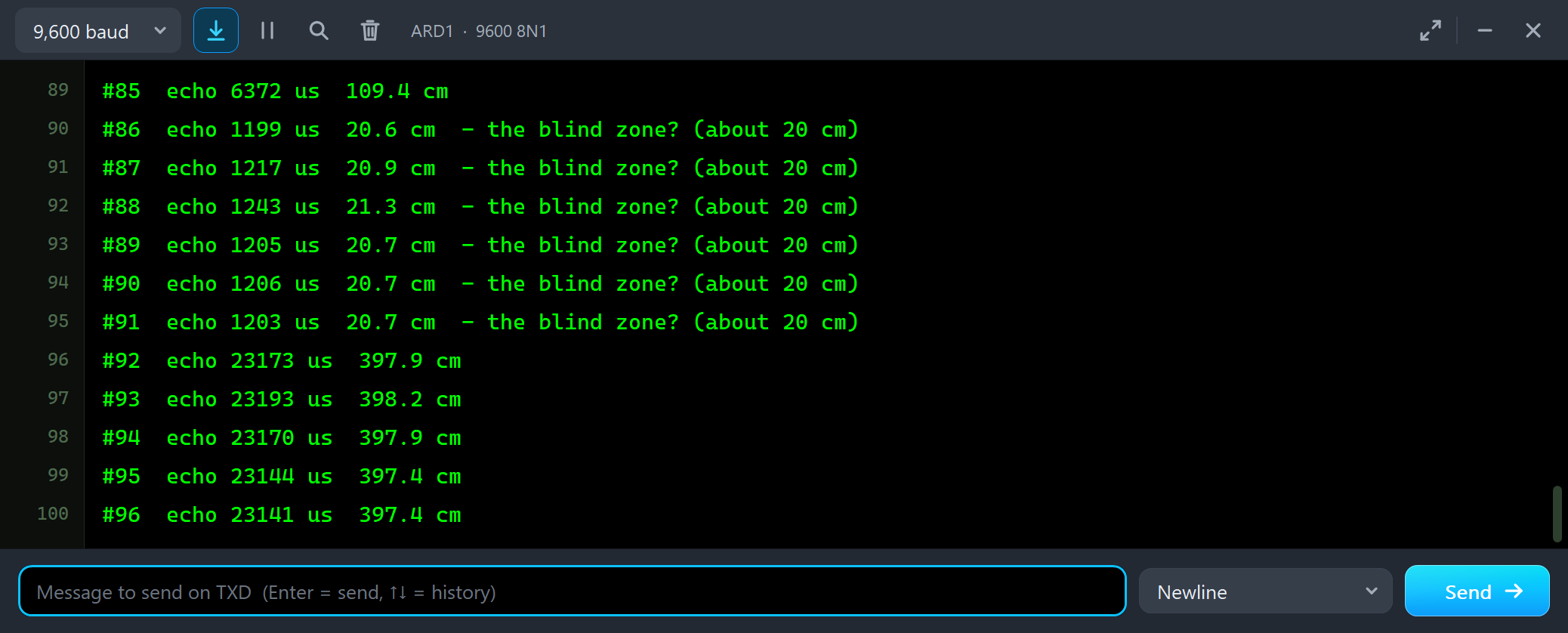
#91  echo 1203 us  20.7 cm  - the blind zone? (about 20 cm)
#92  echo 23173 us  397.9 cm
#93  echo 23193 us  398.2 cm
#94  echo 23170 us  397.9 cm
#95  echo 23144 us  397.4 cm
#96  echo 23141 us  397.4 cm
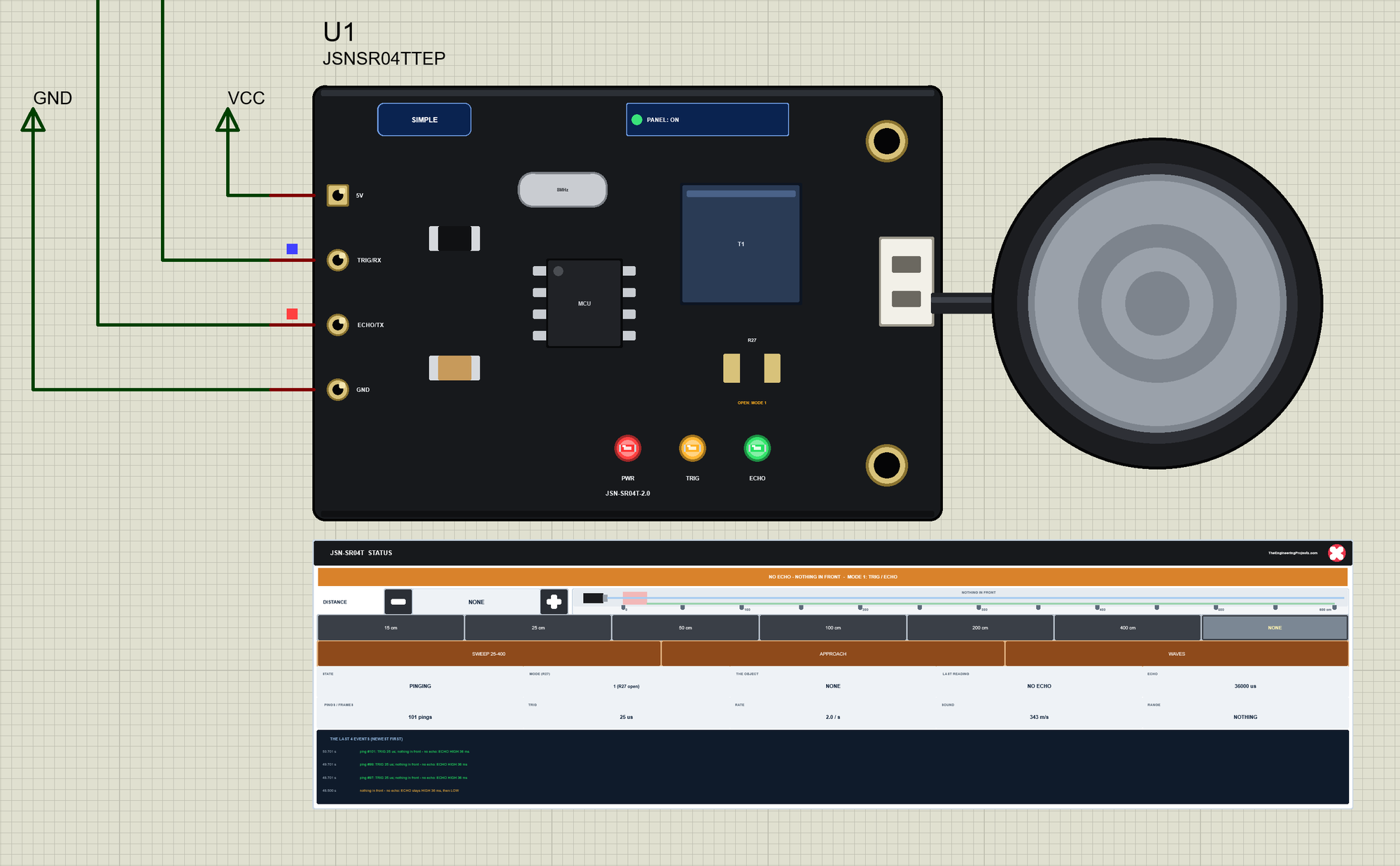
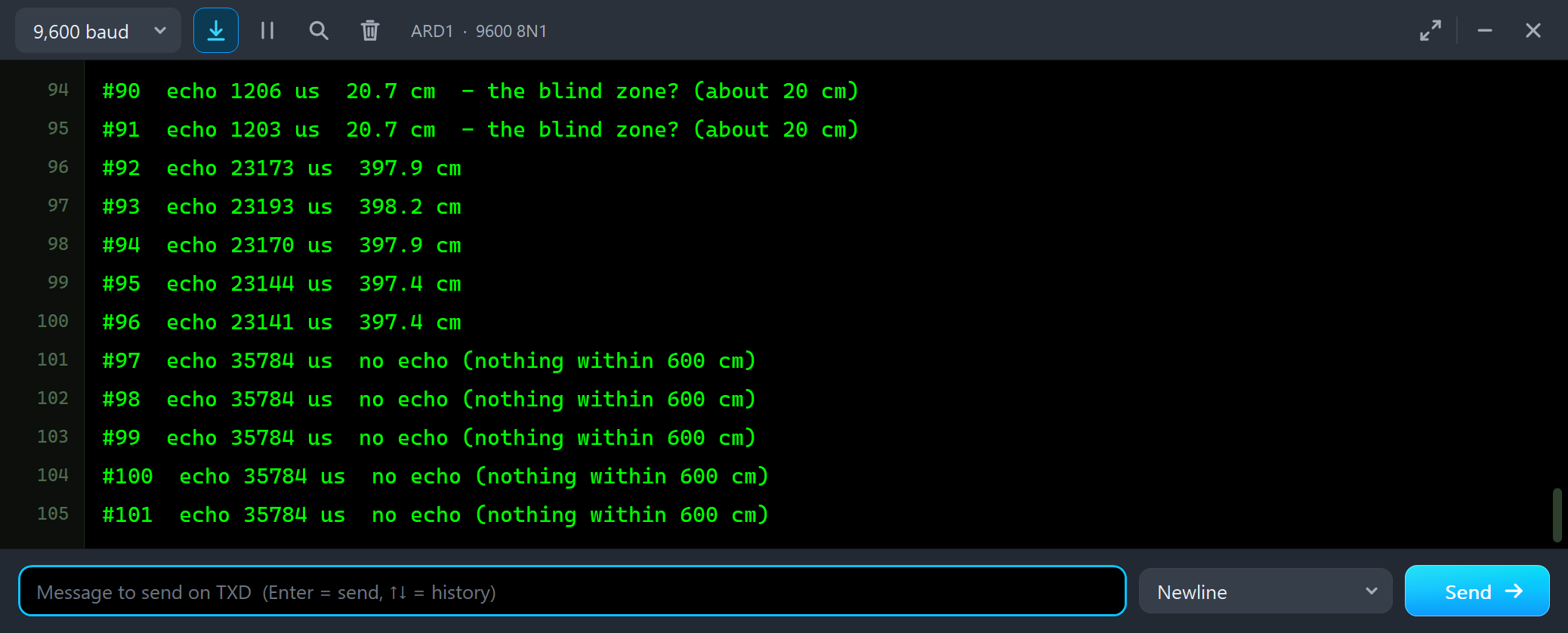
At 400 cm the round trip is 23.30 ms at 343.4 m/s. pulseIn() measures about 23.17 ms and the sketch prints 397.4 to 398.2 cm: the same half percent, which grows with the length of the pulse. With nothing in front:
#96  echo 23141 us  397.4 cm
#97  echo 35784 us  no echo (nothing within 600 cm)
#98  echo 35784 us  no echo (nothing within 600 cm)
#99  echo 35784 us  no echo (nothing within 600 cm)
#100  echo 35784 us  no echo (nothing within 600 cm)
The module keeps ECHO HIGH for 36 ms - pulseIn() says 35784 us - and the sketch treats anything above 35.5 ms as no echo. Without that check it would print about 614 cm, a distance that is not there.
APPROACH: into the Blind Zone
#112  echo 1643 us  28.2 cm
#113  echo 1415 us  24.3 cm
#114  echo 1204 us  20.7 cm  - the blind zone? (about 20 cm)
#115  echo 1208 us  20.7 cm  - the blind zone? (about 20 cm)
#116  echo 1209 us  20.8 cm  - the blind zone? (about 20 cm)
#117  echo 1222 us  21.0 cm  - the blind zone? (about 20 cm)
#118  echo 1204 us  20.7 cm  - the blind zone? (about 20 cm)
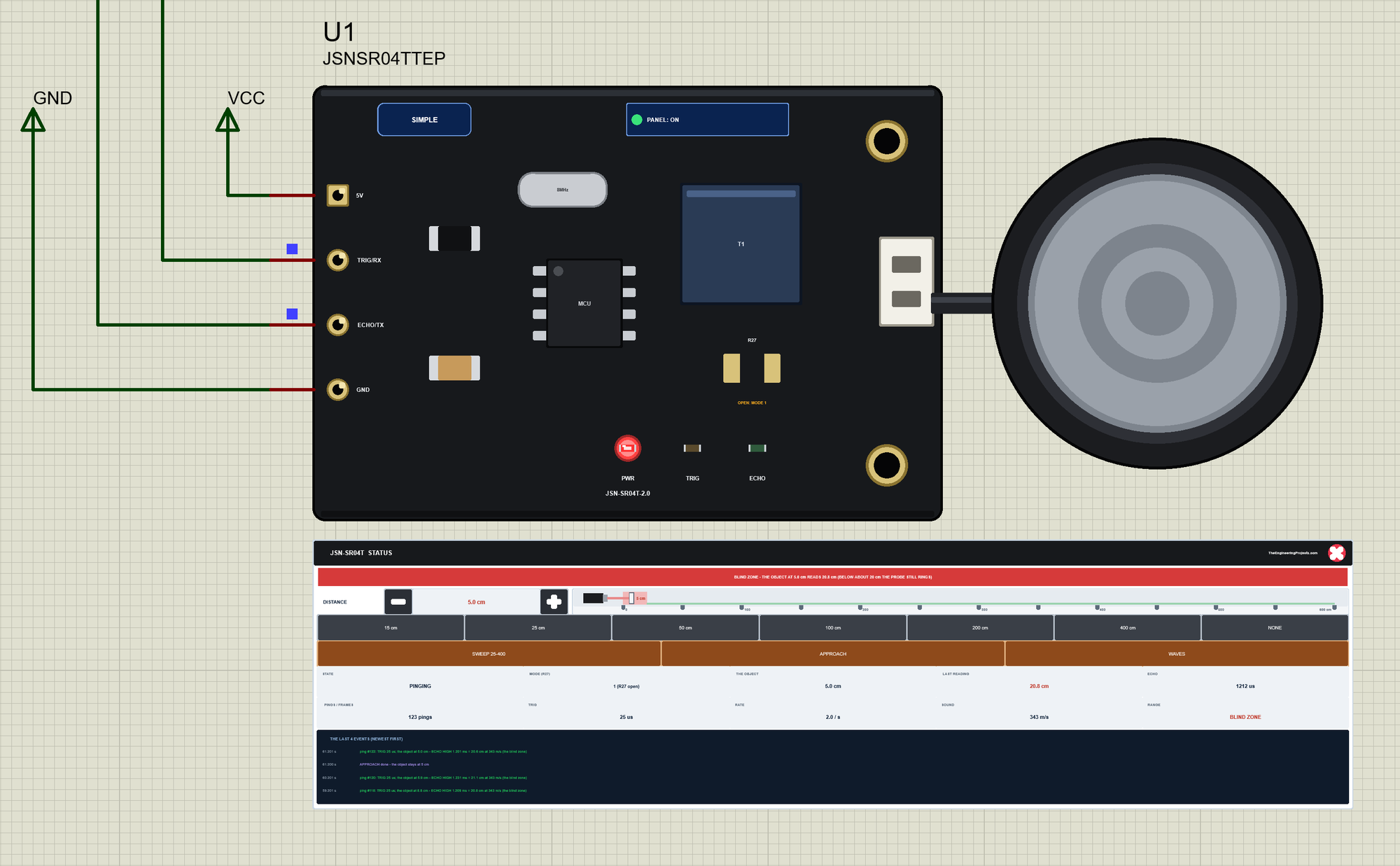
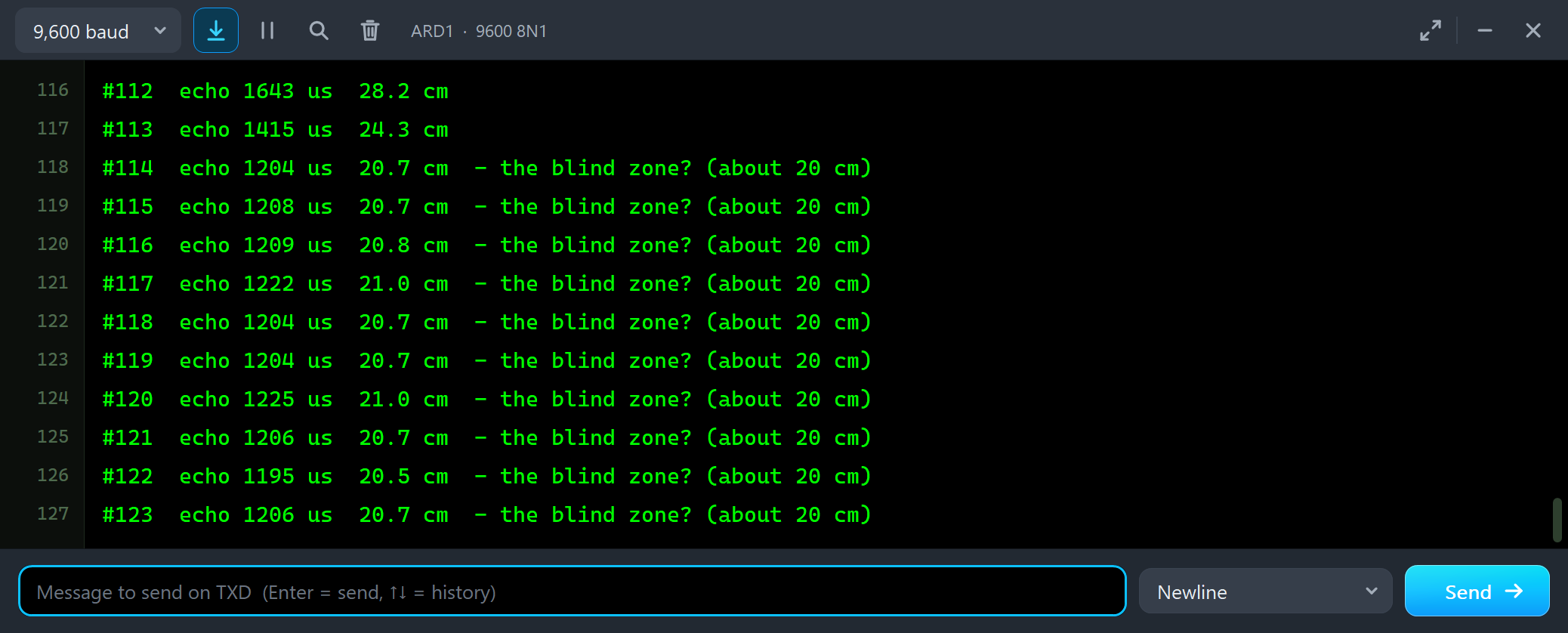
APPROACH brings the object from 100 cm to 5 cm in 10 seconds, slower as it comes close. The readings follow it down to 24.3 cm, then stop at about 20.7 cm while the object goes on to 5 cm: inside the blind zone the module cannot tell 15 cm from 5 cm. A tank filled too high looks almost full to the sensor, never overflowing - so mount the probe 25 cm or more above the highest water level.
TEMP and RAW
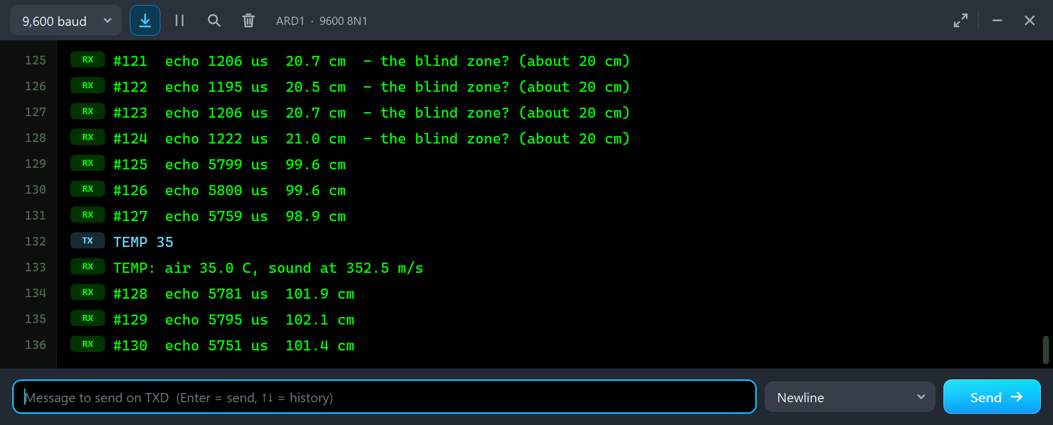
#126  echo 5800 us  99.6 cm
#127  echo 5759 us  98.9 cm
TEMP 35
TEMP: air 35.0 C, sound at 352.5 m/s
#128  echo 5781 us  101.9 cm
#129  echo 5795 us  102.1 cm
#130  echo 5751 us  101.4 cm
#131  echo 5786 us  102.0 cm
TEMP 20
TEMP: air 20.0 C, sound at 343.4 m/s
#132  echo 5767 us  99.0 cm
We told the sketch that the air is at 35 C. The module's air is still at its TEMP property, 20 C, so the ECHO pulses stay the same, but the sketch now multiplies them by 352.5 m/s instead of 343.4: the readings jump from about 99 to about 102 cm, 2.6 % more. It works the other way round too: with the real air at 35 C and the sketch at 20 C, every reading is 2.6 % short. TEMP 20 puts it back. Then we typed RAW:
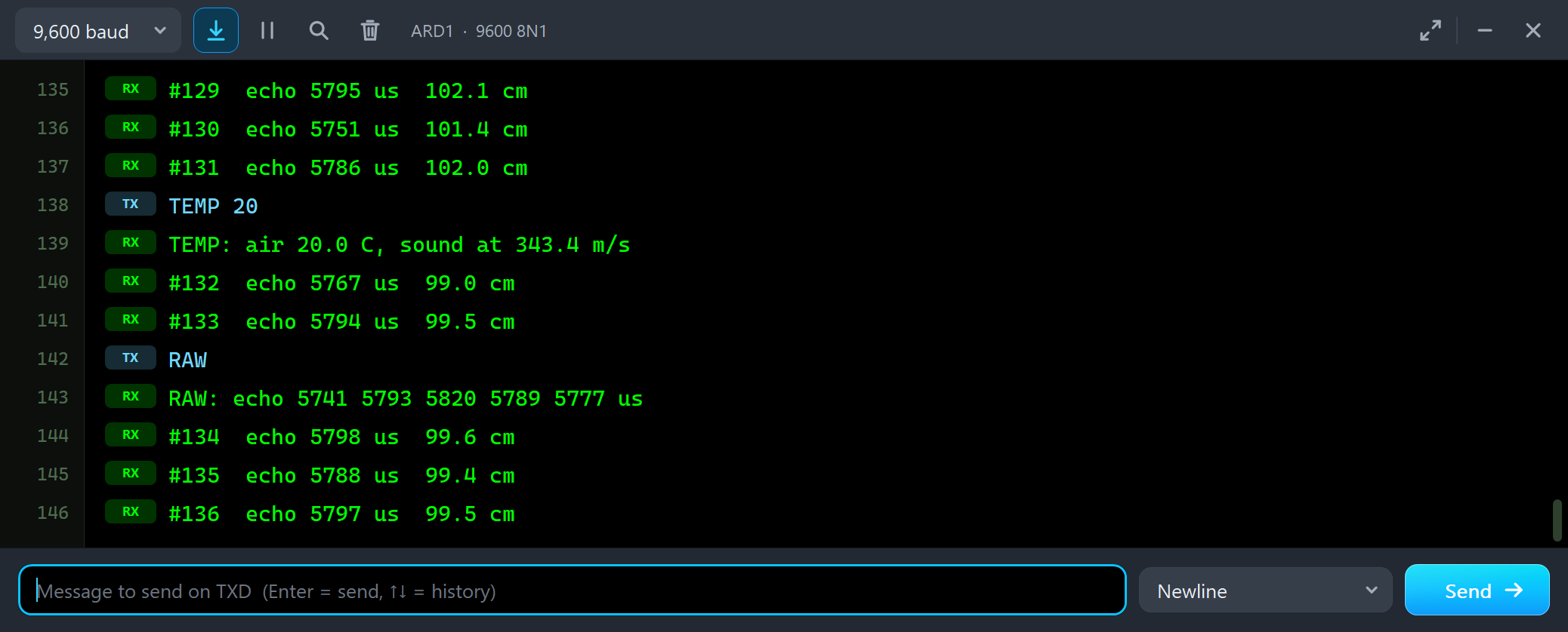
#133  echo 5794 us  99.5 cm
RAW
RAW: echo 5741 5793 5820 5789 5777 us
#134  echo 5798 us  99.6 cm
RAW prints five ECHO widths in a row. Each ping() waits 60 ms after the one before, so the module is always ready; the five values differ only by the noise of each reading.
The Advance Pop-Up Window
At Run, the Advance module opens its own window, JSN-SR04T Waterproof Ultrasonic, with the look of our TEP Serial Monitor Advance for Proteus. It has three tabs, Sensor, Event log and Tests, plus Settings and Help behind the gear and question mark icons. The status bar at the bottom always shows the object, the reading and the mode.
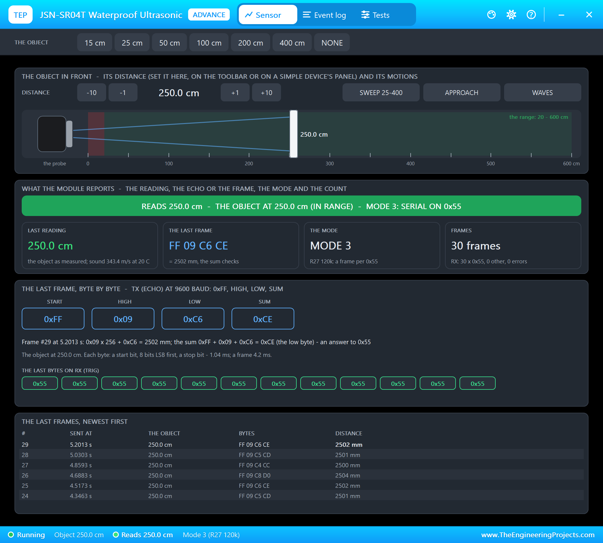
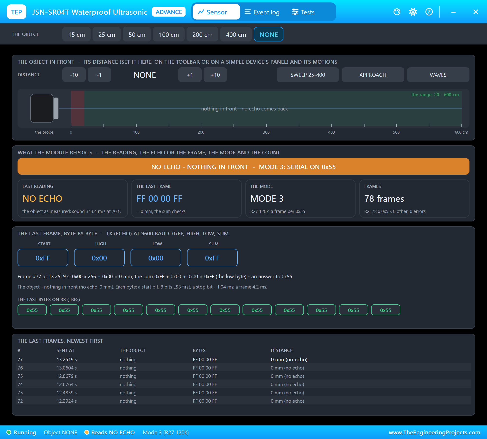
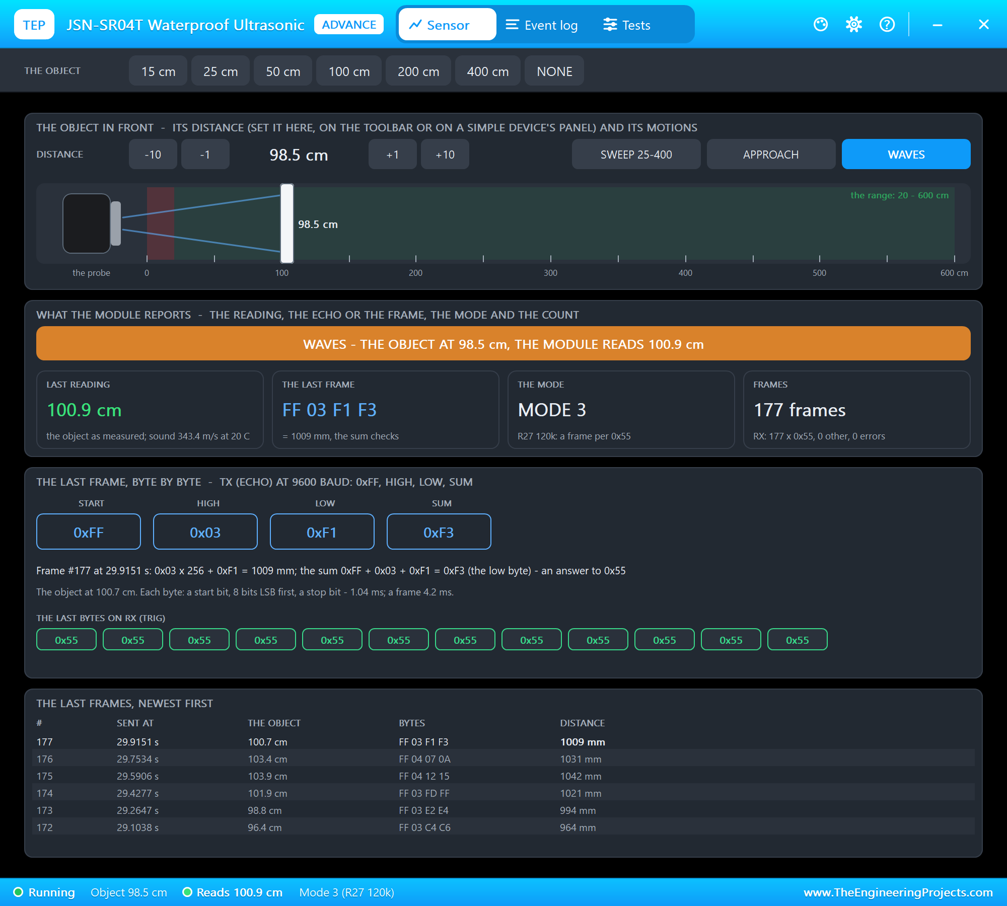
The toolbar carries the presets. The object in front has -10, -1, +1 and +10 cm, the three motions and a side view: the probe, its beam and the object on a ruler, the blind zone shaded red. What the module reports shows the banner, the last reading, the last frame (or the last ECHO pulse in mode 1), the mode and the count. In mode 3, the last frame, byte by byte takes the four bytes apart and lists the bytes received on RX - here all 0x55. At the bottom are the last frames, newest first. We clicked 100 cm:
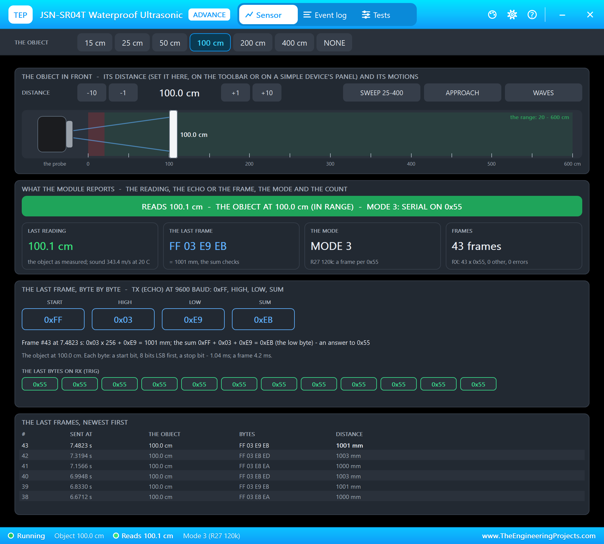
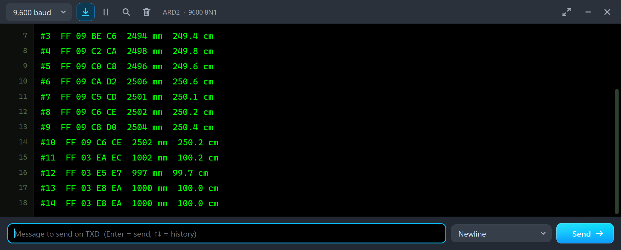
#8  FF 09 C6 CE  2502 mm  250.2 cm
#9  FF 09 C8 D0  2504 mm  250.4 cm
#10  FF 09 C6 CE  2502 mm  250.2 cm
#11  FF 03 EA EC  1002 mm  100.2 cm
#12  FF 03 E5 E7  997 mm  99.7 cm
#13  FF 03 E8 EA  1000 mm  100.0 cm
#14  FF 03 E8 EA  1000 mm  100.0 cm
From one frame to the next the high byte drops from 0x09 to 0x03: FF 03 E8 EA is 0x03E8 = 1000 mm. Then we typed RAW:
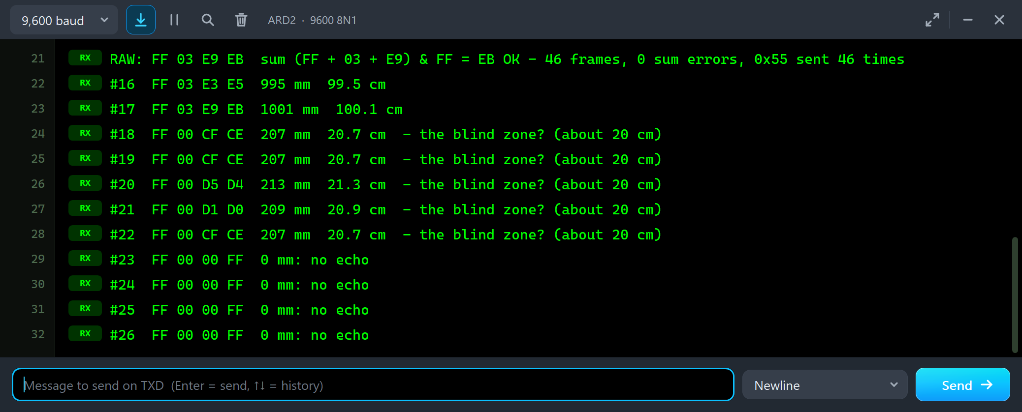
RAW: One Frame Taken Apart
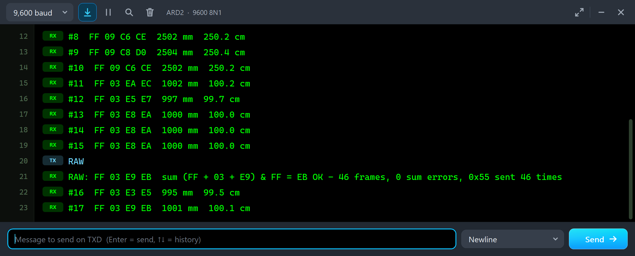
#15  FF 03 E8 EA  1000 mm  100.0 cm
RAW
RAW: FF 03 E9 EB  sum (FF + 03 + E9) & FF = EB OK - 46 frames, 0 sum errors, 0x55 sent 46 times
#16  FF 03 E3 E5  995 mm  99.5 cm
#17  FF 03 E9 EB  1001 mm  100.1 cm
RAW waits for the next frame and takes it apart: FF 03 E9 EB, and (0xFF + 0x03 + 0xE9) & 0xFF = 0xEB, so the sum checks. In the first 46 frames there were no sum errors, and the sketch had sent 0x55 46 times - one frame for each request, as mode 3 should.
15 cm and Nothing in Front
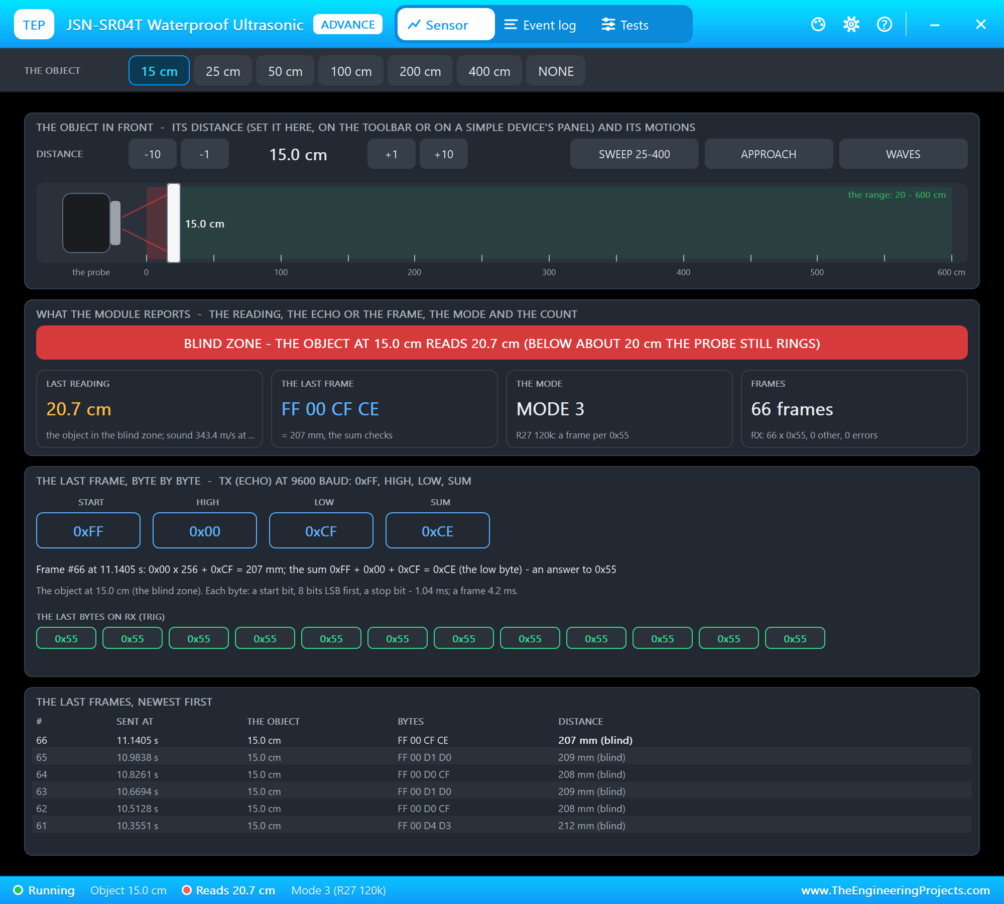
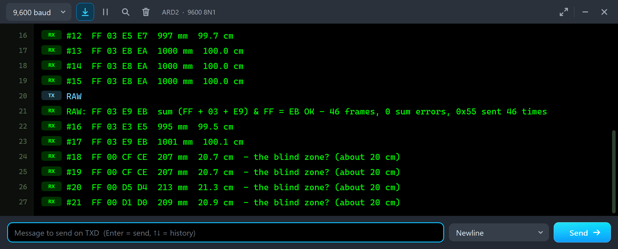
#17  FF 03 E9 EB  1001 mm  100.1 cm
#18  FF 00 CF CE  207 mm  20.7 cm  - the blind zone? (about 20 cm)
#19  FF 00 CF CE  207 mm  20.7 cm  - the blind zone? (about 20 cm)
#20  FF 00 D5 D4  213 mm  21.3 cm  - the blind zone? (about 20 cm)
#21  FF 00 D1 D0  209 mm  20.9 cm  - the blind zone? (about 20 cm)
The serial modes have the same blind zone: the module measures the same way and sends what it heard, about 207 mm. With nothing in front:
#22  FF 00 CF CE  207 mm  20.7 cm  - the blind zone? (about 20 cm)
#23  FF 00 00 FF  0 mm: no echo
#24  FF 00 00 FF  0 mm: no echo
#25  FF 00 00 FF  0 mm: no echo
#26  FF 00 00 FF  0 mm: no echo
With no echo the frame carries 0 mm. The sum still checks - 0xFF + 0x00 + 0x00 = 0xFF - so a sketch must look at the distance itself, not only at the sum.
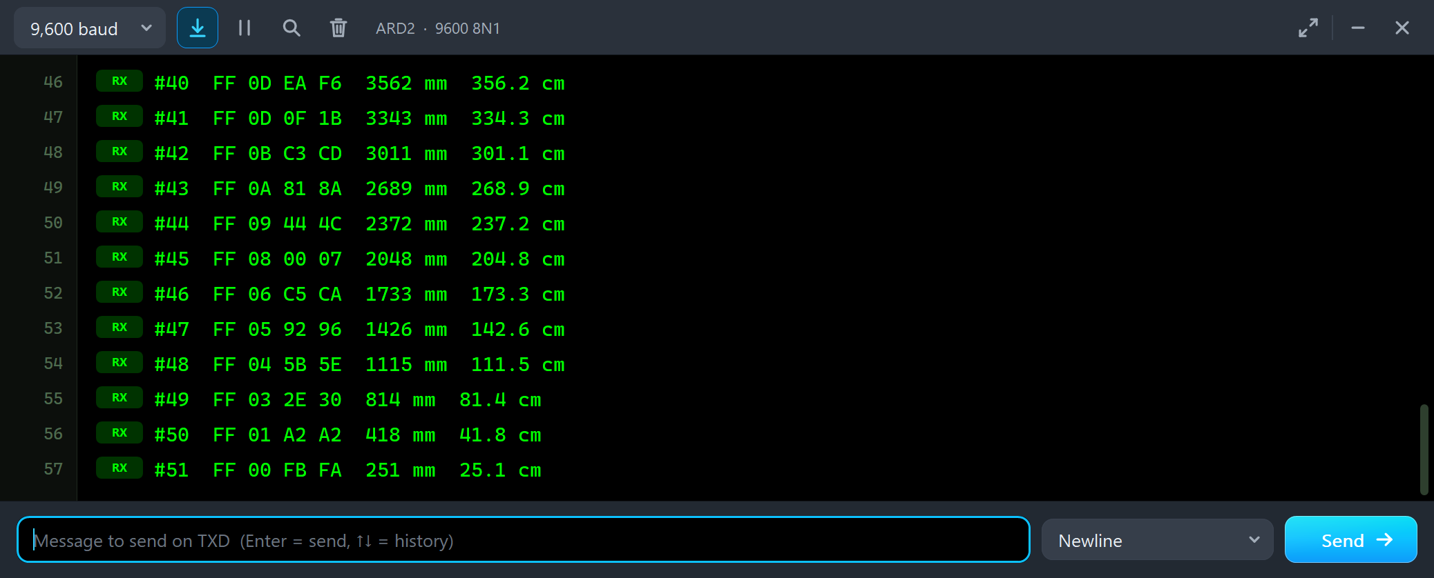
SWEEP 25-400
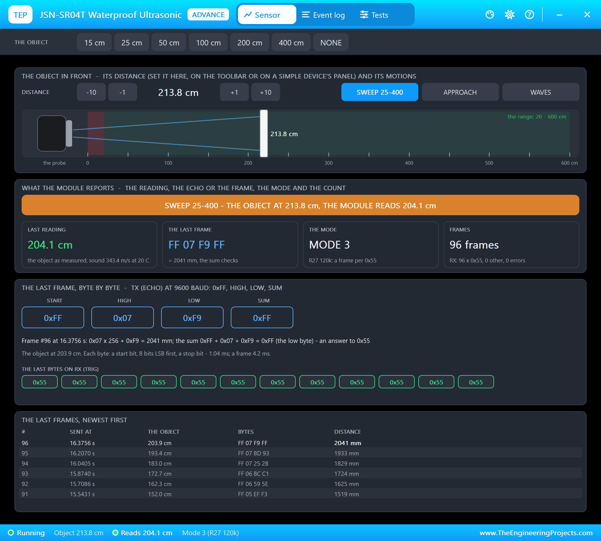
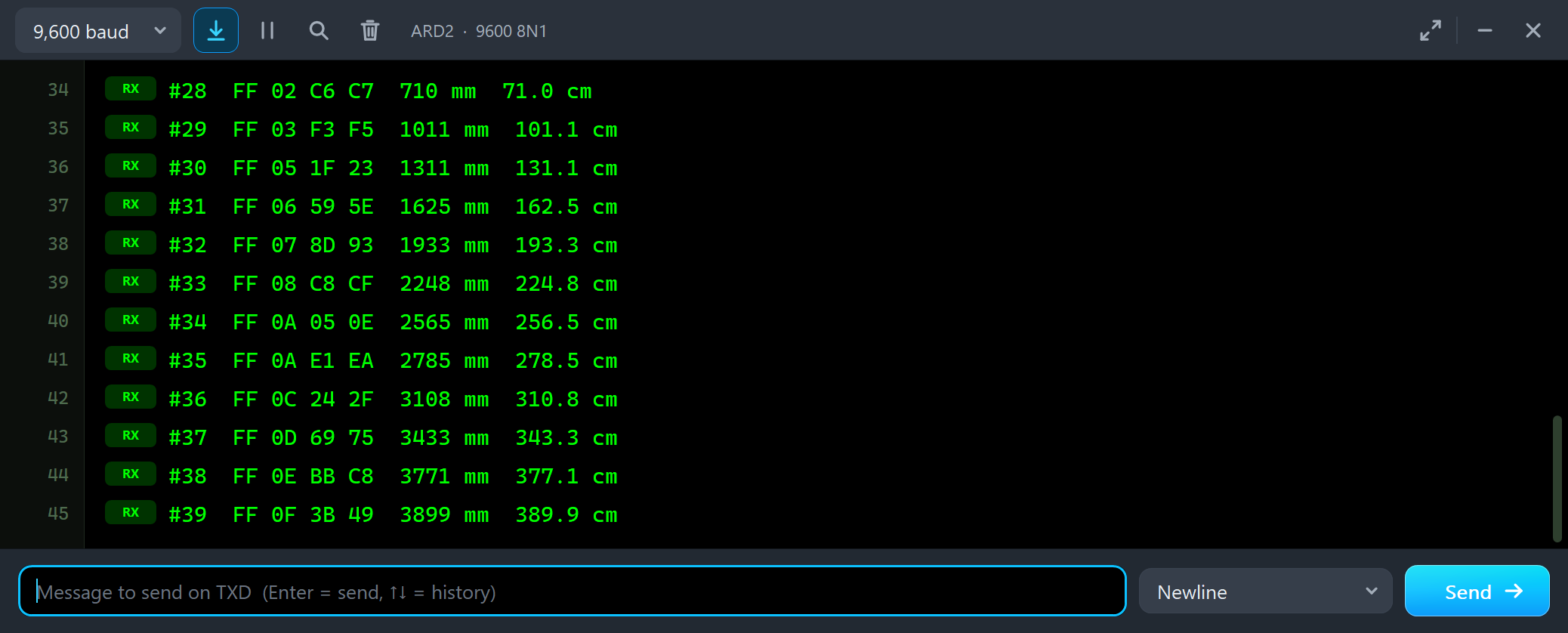
SWEEP 25-400 moves the object from 25 to 400 cm and back in 12 seconds:
#28  FF 02 C6 C7  710 mm  71.0 cm
#29  FF 03 F3 F5  1011 mm  101.1 cm
#30  FF 05 1F 23  1311 mm  131.1 cm
#31  FF 06 59 5E  1625 mm  162.5 cm
#32  FF 07 8D 93  1933 mm  193.3 cm
#33  FF 08 C8 CF  2248 mm  224.8 cm
#34  FF 0A 05 0E  2565 mm  256.5 cm
#35  FF 0A E1 EA  2785 mm  278.5 cm
#36  FF 0C 24 2F  3108 mm  310.8 cm
#37  FF 0D 69 75  3433 mm  343.3 cm
#38  FF 0E BB C8  3771 mm  377.1 cm
#39  FF 0F 3B 49  3899 mm  389.9 cm
and back in:
#40  FF 0D EA F6  3562 mm  356.2 cm
#41  FF 0D 0F 1B  3343 mm  334.3 cm
#42  FF 0B C3 CD  3011 mm  301.1 cm
#43  FF 0A 81 8A  2689 mm  268.9 cm
#44  FF 09 44 4C  2372 mm  237.2 cm
#45  FF 08 00 07  2048 mm  204.8 cm
#46  FF 06 C5 CA  1733 mm  173.3 cm
#47  FF 05 92 96  1426 mm  142.6 cm
#48  FF 04 5B 5E  1115 mm  111.5 cm
#49  FF 03 2E 30  814 mm  81.4 cm
#50  FF 01 A2 A2  418 mm  41.8 cm
#51  FF 00 FB FA  251 mm  25.1 cm
The object moves about 62 cm a second and the lines are half a second apart, so the readings climb by about 31 cm a line. Look at #45: FF 08 00 07. The low byte is 0x00 and the sum is 0x07, because 0xFF + 0x08 + 0x00 = 0x107. At #50 the sum byte equals the low byte. Any value can turn up in a frame, which is why the sketch accepts four bytes only when they start with 0xFF and the sum checks.
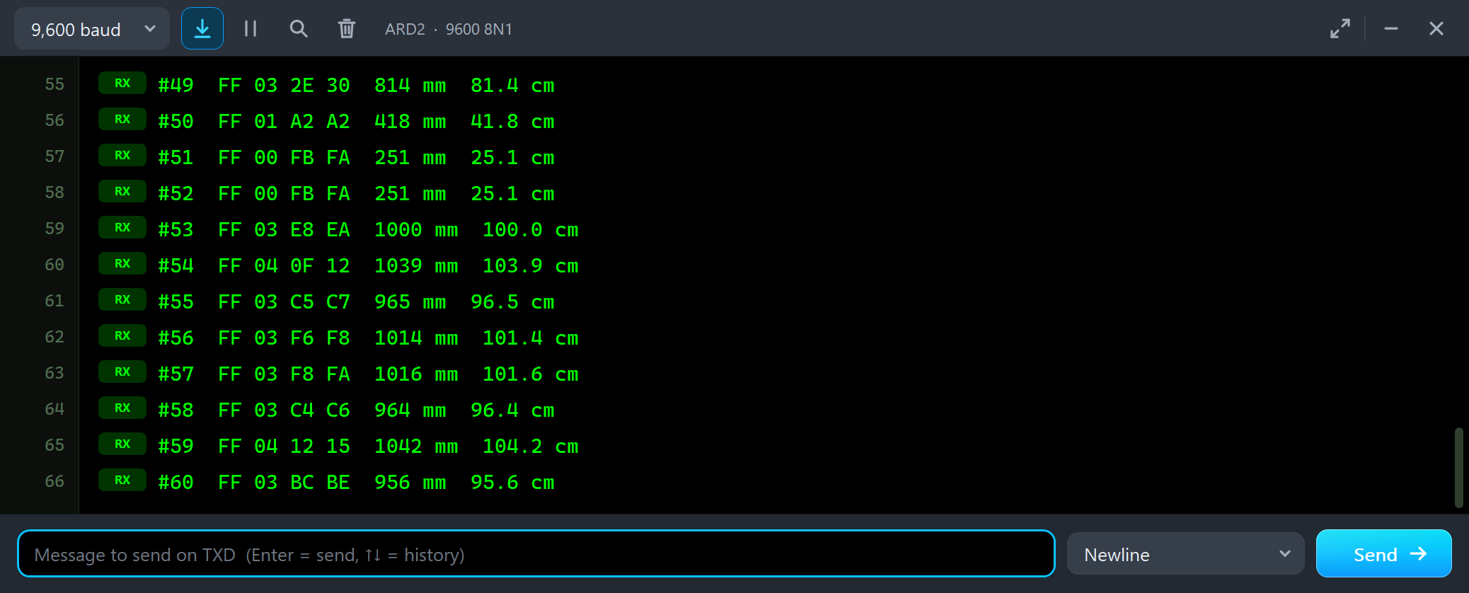
WAVES: a Water Surface
#52  FF 00 FB FA  251 mm  25.1 cm
#53  FF 03 E8 EA  1000 mm  100.0 cm
#54  FF 04 0F 12  1039 mm  103.9 cm
#55  FF 03 C5 C7  965 mm  96.5 cm
#56  FF 03 F6 F8  1014 mm  101.4 cm
#57  FF 03 F8 FA  1016 mm  101.6 cm
#58  FF 03 C4 C6  964 mm  96.4 cm
#59  FF 04 12 15  1042 mm  104.2 cm
#60  FF 03 BC BE  956 mm  95.6 cm
WAVES turns the object into a water surface at 100 cm that moves 4 cm up and down 0.8 times a second, and the readings swing between 95.6 and 104.2 cm. In a real tank, take the median or the average of a few readings before you show a level.
The Test Tools
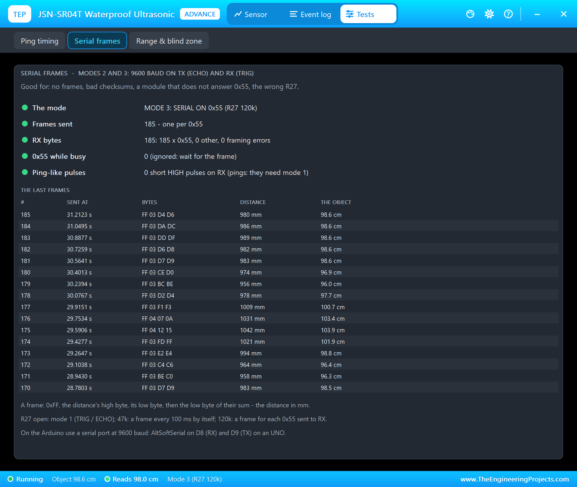
The Serial frames tool is the one to open when no data comes or the sums fail. It shows the mode with R27, the frames sent - one per 0x55 here - the bytes received on RX (0x55, other bytes and framing errors), the 0x55 that came while a measurement was still going, and pulses on RX that look like pings. Below are the last frames with their bytes, the distance and where the object really was.
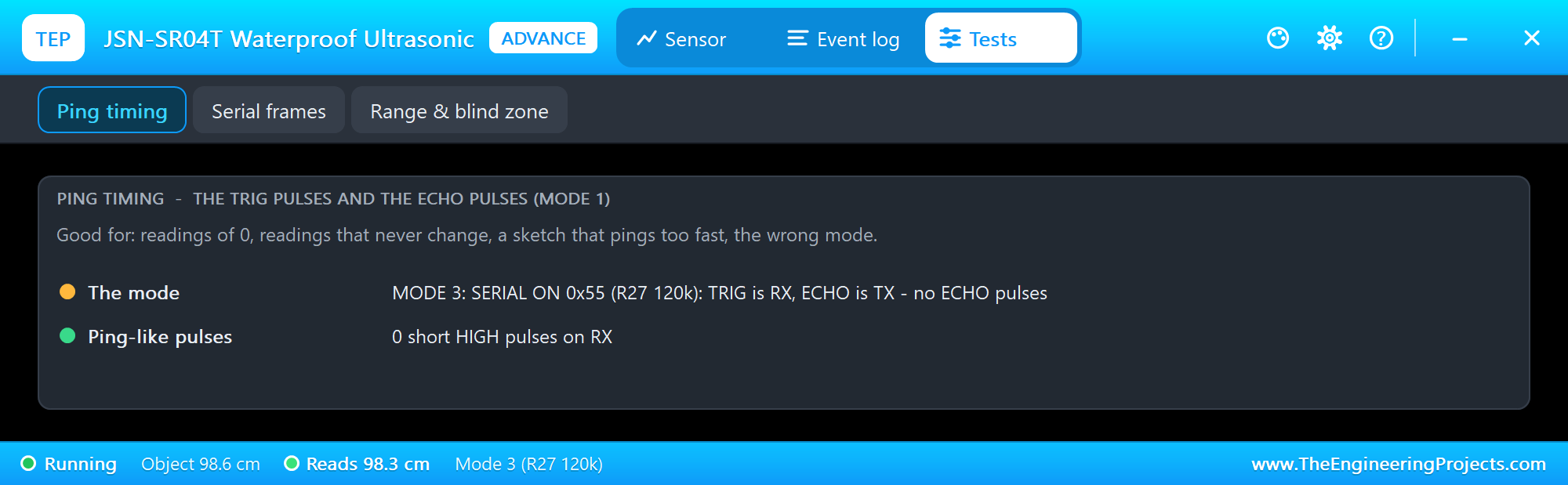
The Ping timing tool is for mode 1. On U2 it explains why there are no ECHO pulses: the module is in mode 3, where TRIG is RX and ECHO is TX. In mode 1 it shows the pings and their rate, the last TRIG pulse, pulses that were too short or too early, TRIG held HIGH, and the last echo.
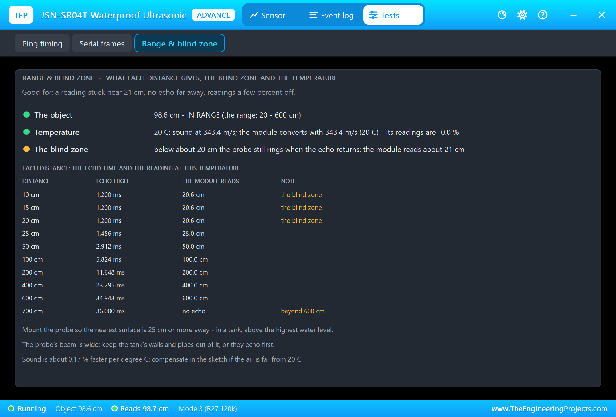
The Range & blind zone tool lists, at the air temperature, how long ECHO is for each distance from 10 to 700 cm and what the module reads: 20.6 cm for 10, 15 and 20 cm (the blind zone), 5.824 ms for 100 cm, 34.943 ms for 600 cm, and no echo at 700 cm. It also compares the speed of sound at TEMP with the 343.4 m/s the module converts with.
The Event Log
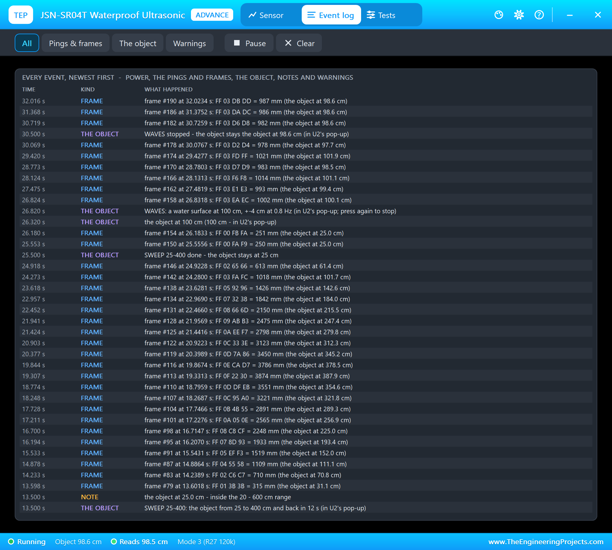
The Event log lists everything that happened, newest first: power, the pings or frames (two a second), the object and its motions, notes and warnings. Filter it by pings and frames, the object or warnings, pause it, or clear it.
The Simulation Log
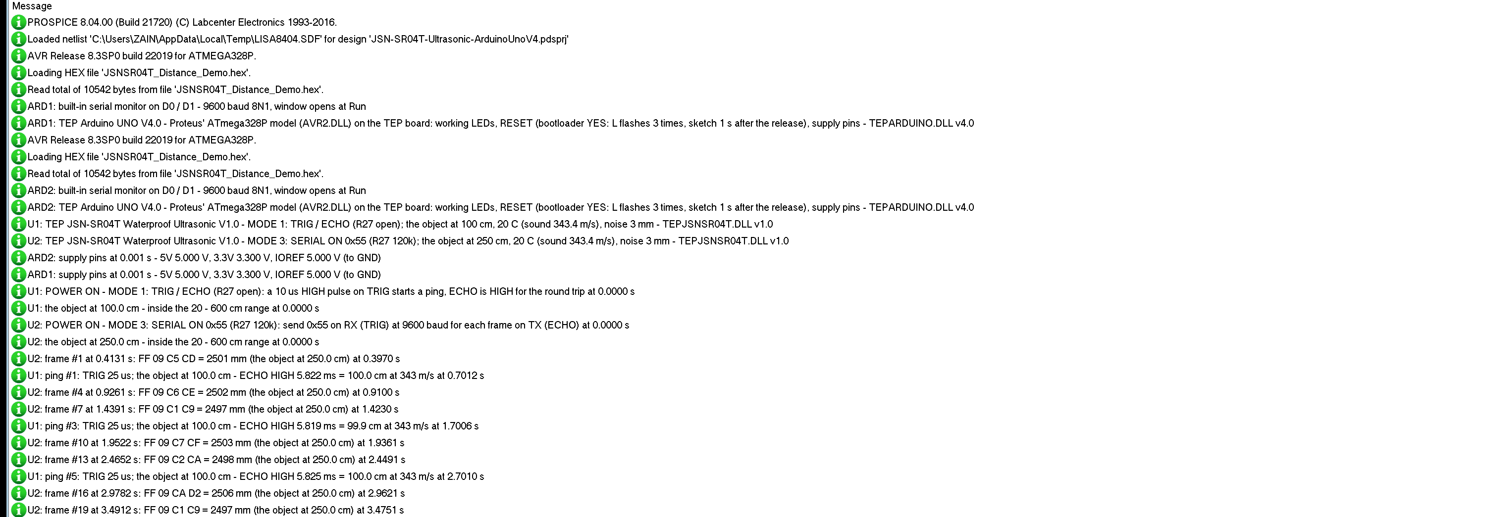
The modules also write to the simulation log of Proteus, with the exact simulation time. This part shows both:
U1: TEP JSN-SR04T Waterproof Ultrasonic V1.0 - MODE 1: TRIG / ECHO (R27 open); the object at 100 cm, 20 C (sound 343.4 m/s), noise 3 mm - TEPJSNSR04T.DLL v1.0
U2: TEP JSN-SR04T Waterproof Ultrasonic V1.0 - MODE 3: SERIAL ON 0x55 (R27 120k); the object at 250 cm, 20 C (sound 343.4 m/s), noise 3 mm - TEPJSNSR04T.DLL v1.0
U1: POWER ON - MODE 1: TRIG / ECHO (R27 open): a 10 us HIGH pulse on TRIG starts a ping, ECHO is HIGH for the round trip at 0.0000 s
U2: POWER ON - MODE 3: SERIAL ON 0x55 (R27 120k): send 0x55 on RX (TRIG) at 9600 baud for each frame on TX (ECHO) at 0.0000 s
U2: frame #1 at 0.4131 s: FF 09 C5 CD = 2501 mm (the object at 250.0 cm) at 0.3970 s
U1: ping #1: TRIG 25 us; the object at 100.0 cm - ECHO HIGH 5.822 ms = 100.0 cm at 343 m/s at 0.7012 s
U1: ping #3: TRIG 25 us; the object at 100.0 cm - ECHO HIGH 5.819 ms = 99.9 cm at 343 m/s at 1.7006 s
U2's first frame shows the timing of mode 3: the 0x55 was decoded at 0.3970 s, and the frame started at 0.4131 s - the rest of the byte, 0.5 ms for the burst, 14.6 ms for the round trip to 250 cm and 1 ms to prepare the frame. U1's ping #1 had an ECHO pulse of 5.822 ms: the one the sketch printed as 5785 us. The log has one ping or frame every half second; the Event log has more.
How the Model Works
The module is a digital model. 5V and GND power it. In mode 1 it watches TRIG: when a HIGH pulse of 10 us or more ends, it takes the object's distance at that moment, works out the round trip at the speed of sound for TEMP, adds that reading's noise and the blind zone, and schedules the ECHO pulse: HIGH 0.5 ms after the trigger, LOW one round trip later. In modes 2 and 3 the same pins become a 9600-baud UART: the model decodes the bytes on RX bit by bit, and sends each frame on TX with every bit at its exact time. Proteus calls the model only at those edges, so it costs very little time.
Troubleshooting
- Mode 1 prints "no ECHO pulse": no power, TRIG and ECHO swapped, or the module is in mode 2 or 3 - look at R27 on the board or the MODE property; the log warns about pings sent to a serial board.
- The serial modes print "no frame yet": TX and RX swapped, D2 not at GND, or the module is in mode 1.
- The reading stays at about 21 cm: the object is in the blind zone.
- "no echo" or 0 mm: nothing in front, or farther than 600 cm.
- A few percent off: the air temperature - TEMP in the sketch for mode 1; in modes 2 and 3 the module converts by itself.
- Readings that repeat or are missing: pings faster than one per 50 ms are ignored; the Ping timing tool counts them.
- No part or no monitor: TEPJSNSR04T.DLL or TEPARDUINO.DLL is missing from MODELS and the project folder; a closed monitor opens again with a click on the UNO's USB port.
Things to Know Before Using a Real JSN-SR04T
- Check R27: the mode is a resistor on the R27 pad (empty for mode 1) - other versions of the board, and similar boards, use other pads and values.
- Mount the probe square to the surface it measures, away from the walls of a tank; condensation on the probe changes the readings.
- Keep 25 cm or more between the probe and the nearest surface - in a tank, above the highest water level. Our Water Level Indicator using Arduino shows the idea with an Arduino.
- Ping no faster than every 60 ms or so: the last echoes must die away.
- Mind the levels: the board runs from 3.0 to 5.5 V and ECHO / TX is at its supply level - at 5 V use a divider into a 3.3 V board.
Limitations of the Simulation
- Not modelled: the supply voltage and current, the beam's width and the object's size, angle and material, several echoes and the tank's walls, condensation, wind and humidity, the board's start-up time and the 40 kHz burst itself. The 1.2 ms blind zone, the 0.5 ms before ECHO, the 36 ms with no echo and the 343.4 m/s the module converts with in the serial modes are the model's values - the datasheets differ between board versions.
- The LEDs, the badge, the panel button and the panels are TEP additions.
- The model is our own, written from the module's published descriptions. This library is not made or endorsed by the makers of the JSN-SR04T or by Labcenter.
- Licences: the demo sketch uses AltSoftSerial 1.4 by Paul Stoffregen (MIT License); it is not in the package, and its licence text is in the README. The HEX file also contains the Arduino AVR core 1.8.6 with LGPL-licensed code; the licence note and the source link are in the README.
- Tested in Proteus 8.5 in October 2026 (the demo as shipped on two Arduino UNO V4.0 boards with their built-in monitors: +, 15 cm, 400 cm, NONE, APPROACH, TEMP and RAW on node 1 in mode 1 with the mouse, the red X and PANEL; 100 cm, RAW, 15 cm, NONE, SWEEP 25-400, WAVES and the three tools on node 2 in mode 3; 77.5 s of simulation took 284 s, about 0.3 x real time with the pop-up and both monitors open). Proteus 7 is not supported.
So, that was all about the JSN-SR04T Waterproof Ultrasonic Sensor Library for Proteus V1.0. I hope the three modes, the frames and the blind zone are clear now, and that your tank or parking project works from the first run. If you use the JSN-SR04T Waterproof Ultrasonic Sensor Library for Proteus in a project, please share it in the comments or in our forum, and if you have any questions, ask in the comments and I will help you out. Till the next tutorial, take care and have fun!
Comments
0