


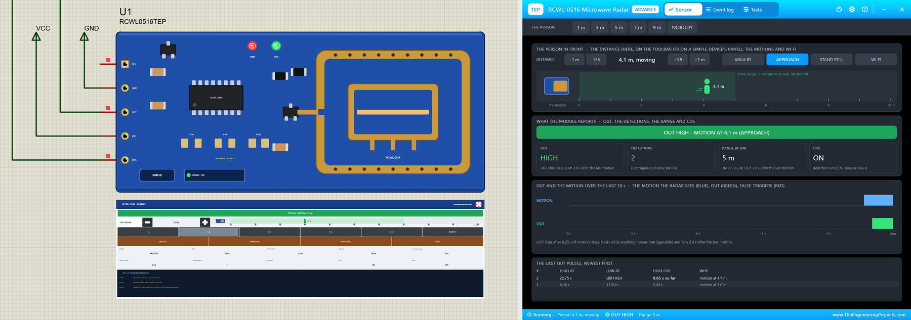
RCWL-0516 Microwave Radar Motion Sensor Library for Proteus V1.0


Hello friends, I hope you all are doing great. Today, I am going to share the new RCWL-0516 Microwave Radar Motion Sensor Library for Proteus V1.0. The RCWL-0516 is the little blue board that many makers now use instead of a PIR sensor: a tiny microwave radar that sees anything moving within about 7 m, all around, even through a plastic case. It switches on the stair light, wakes a project up when someone walks in, or counts the people that pass a door. Now you can test those projects in Proteus.
Behind the part sits our own model, not a switch. OUT rises after a short burst of motion, stays HIGH while anything keeps moving and falls 2 s after the last movement. A person who stands still is not seen, a person beyond the range is not seen, the CDS pin switches detection off, and a Wi-Fi module right next to the board brings the false triggers real users complain about. You move the person, pick a preset, or let them walk by or approach. You get two devices: a Simple device with a live STATUS panel and an Advance device with a pop-up window and the test tools. The demo runs on our Arduino UNO V4.0.
NOTICE: a motion sensor is easy to fake: a button that sets OUT HIGH. We wanted more. Our RCWL-0516 has the real board's timing, its range, its blindness to people who stand still, its CDS input and its false triggers, so a sketch that counts every step as a new visitor, or a light that never goes out, fails exactly as it does with the real module. It took our team a lot of hard work. Your feedback is the fuel that keeps us going, so please tell us what you think in the comments below or in the RCWL-0516 board of our forum. And if our free libraries help you, you can buy us a coffee. So, let's get started with the RCWL-0516 Microwave Radar Motion Sensor Library for Proteus V1.0:
What is the RCWL-0516?
The RCWL-0516 is a microwave Doppler radar on a small board. An oscillator at about 3.2 GHz feeds an antenna made of copper on the board itself, and the waves go out all around. When something moves, the echo comes back at a slightly different frequency - the Doppler effect - and the RCWL-9196 chip turns that into a clean digital output. The chip works like the BISS0001 of the PIR sensors, and the result looks the same to an Arduino: OUT goes HIGH when something moves. If you know our PIR Sensor Library for Proteus V4.0, you will feel at home; the difference is in what the two sensors see.
| RCWL-0516 | |
|---|---|
| Detects | motion only (the Doppler effect), all around |
| Range | about 7 m (R-GN empty), 5 m with 1M on R-GN |
| Supply (VIN) | 4 to 28 V |
| OUT | 3.3 V when HIGH; LOW 2 s after the last motion (C-TM empty) |
| CDS | below 0.7 V: detection off (a light-sensor input) |
| 3V3 | a 3.3 V output of the board's regulator |
| Devices | RCWL0516TEP (Simple) and RCWL0516ADVTEP (Advance) |
Radar or PIR?
A PIR sensor sees the heat of a body crossing its zones, through a lens in front. The radar sees motion, of anything, all around: through a plastic case, through a thin wall, a fan or a curtain as well as a person. That makes it easy to hide inside a lamp, and also easy to fool. Neither of them sees a person who sits perfectly still. For the PIR side of the story, read our PIR Sensor Arduino Interfacing and Motion Detection with ESP32 and a PIR Sensor; for radar sensors that also measure the distance, see FMCW radar sensors for IoT and health care.
The Pads: C-TM, R-GN and R-CDS
Three pairs of empty pads sit on the real board. A capacitor on C-TM makes OUT stay HIGH longer than the 2 s of an empty pad. A resistor on R-GN lowers the gain: 1M cuts the range from about 7 m to about 5 m. A resistor on R-CDS, together with an LDR on the CDS pin, sets how dark it must be before the sensor works. In the library, the properties HOLD and RGN play the parts of C-TM and R-GN, and the board draws what they mean.
What's New in RCWL-0516 Microwave Radar Motion Sensor Library for Proteus V1.0
- The real module: the blue board with its 5-pin header, the RCWL-9196 chip, the regulator, the RF transistor, the C-TM, R-GN and R-CDS pads and the copper of the antenna. The board draws 105 (1M) on R-GN and a capacitor on C-TM when the properties ask for them, and writes the range and the hold under the pads.
- Two styles: a Simple device with a STATUS panel and an Advance device with a pop-up window; the PWR and OUT LEDs and the panel button sit on the board.
- OUT's timing: HIGH after 0.25 s of motion, HIGH while the motion goes on (one long pulse, not one per step), LOW 2 s after the last movement (HOLD).
- What a radar sees: motion only - a person standing still is not seen - within 7 m, or 5 m with 1M on R-GN.
- CDS: LOW switches detection off; OUT finishes its time first.
- Wi-Fi false triggers: a WI-FI switch puts a transmitter next to the board, and now and then OUT goes HIGH with nothing moving.
- The person on the panel: the distance in 0.5 m steps, presets 1, 3, 5, 7, 9 m and NOBODY, and four actions: WALK BY, APPROACH, STAND STILL and WI-FI.
- Three test tools on the Advance device: Output timing, Range & motion, and Interference & CDS.
- A two-node demo on our Arduino UNO V4.0: an interrupt on D2 catches every edge of OUT with its time, and the sketch switches CDS from the serial monitor - no library needed.
- A compact package: about 1.25 MB, without the C++ source code of the model.
Two Devices: Simple and Advance
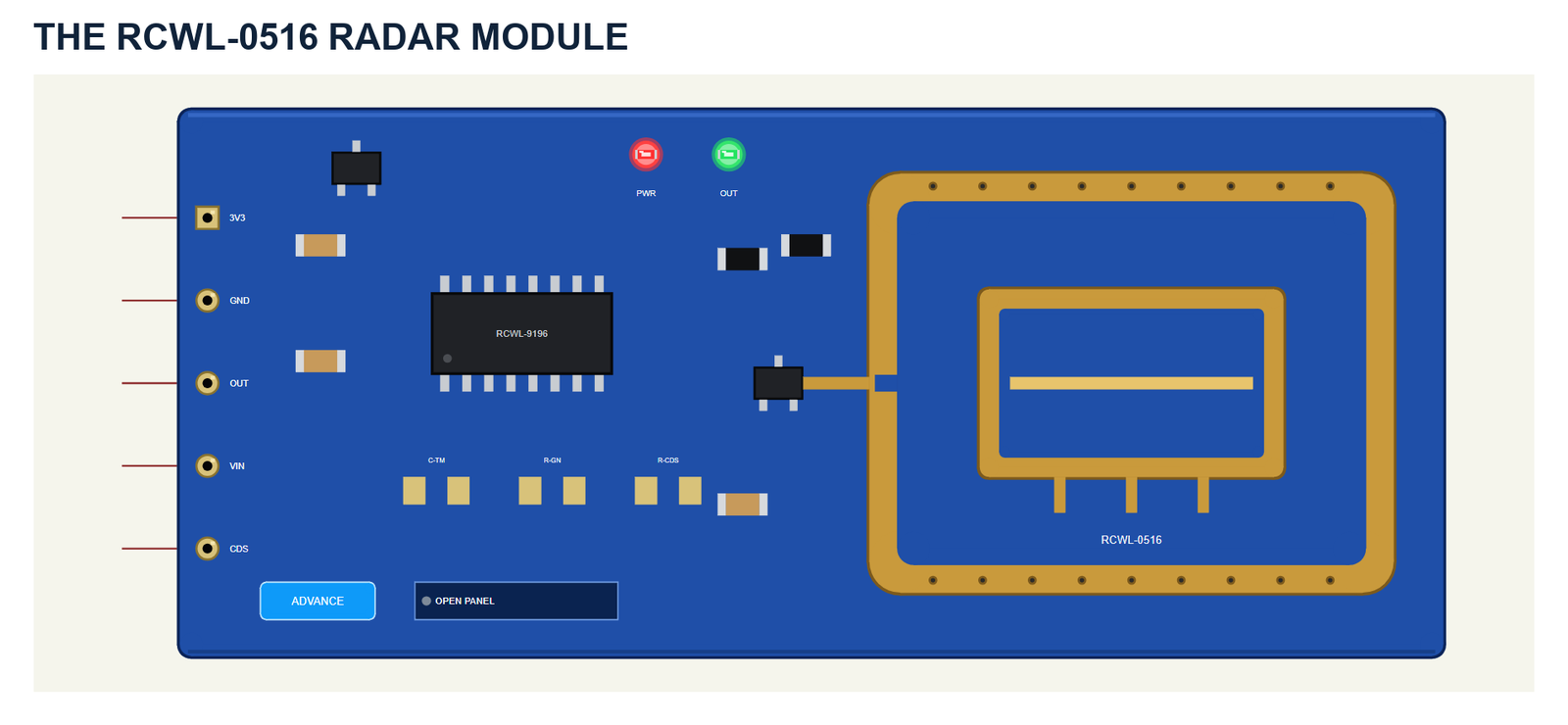
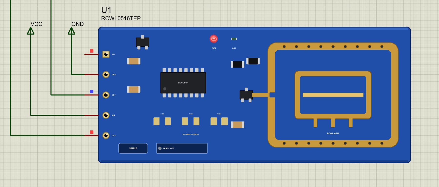
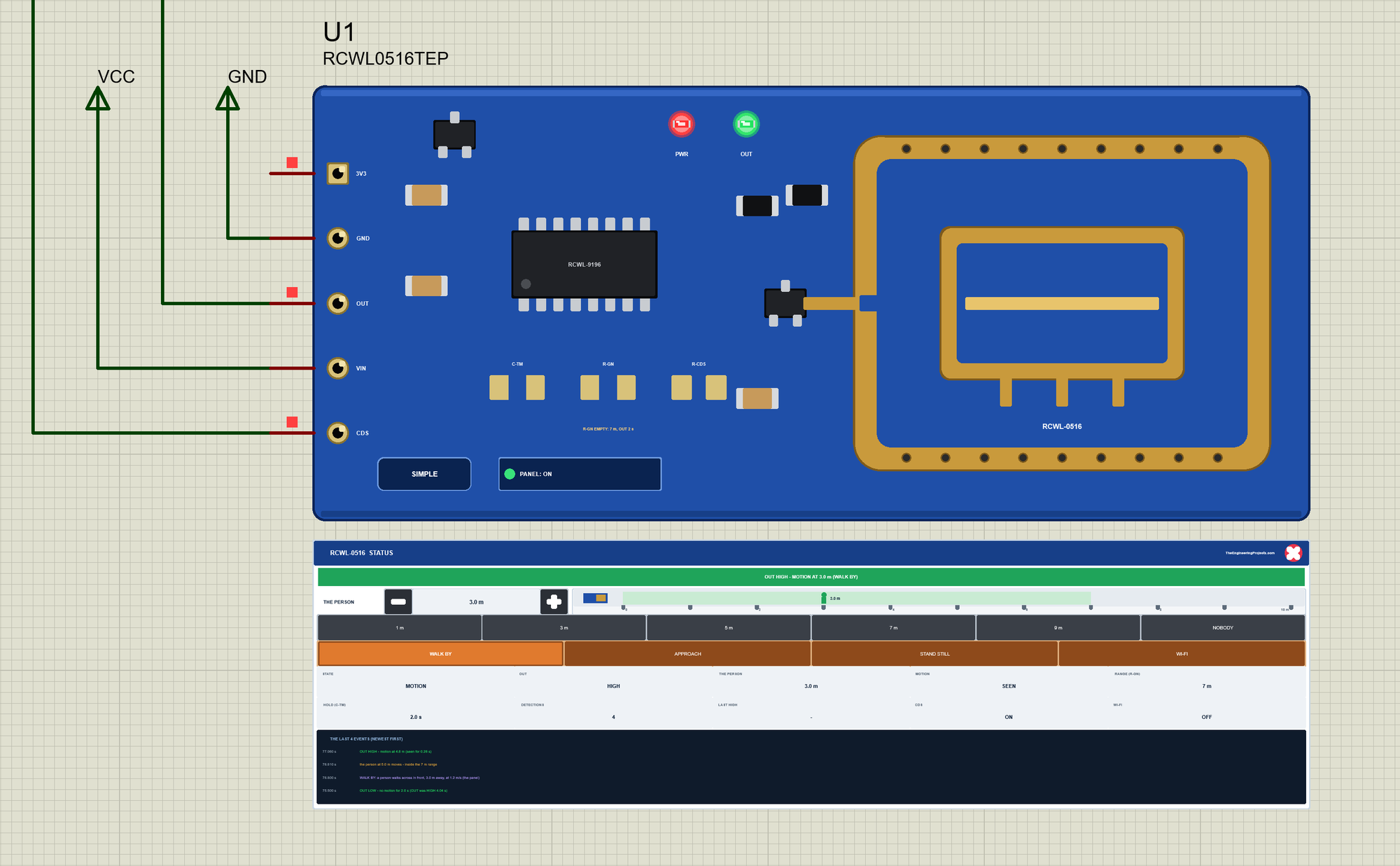
On the left is the header with its silk labels 3V3, GND, OUT, VIN and CDS; these are the part's pins. The board carries the RCWL-9196 chip, the regulator, the RF transistor next to the antenna and the three pads, C-TM, R-GN and R-CDS, all empty here. The copper loop on the right is the antenna. The board is drawn at about three times its real size, so you can read it on the schematic.
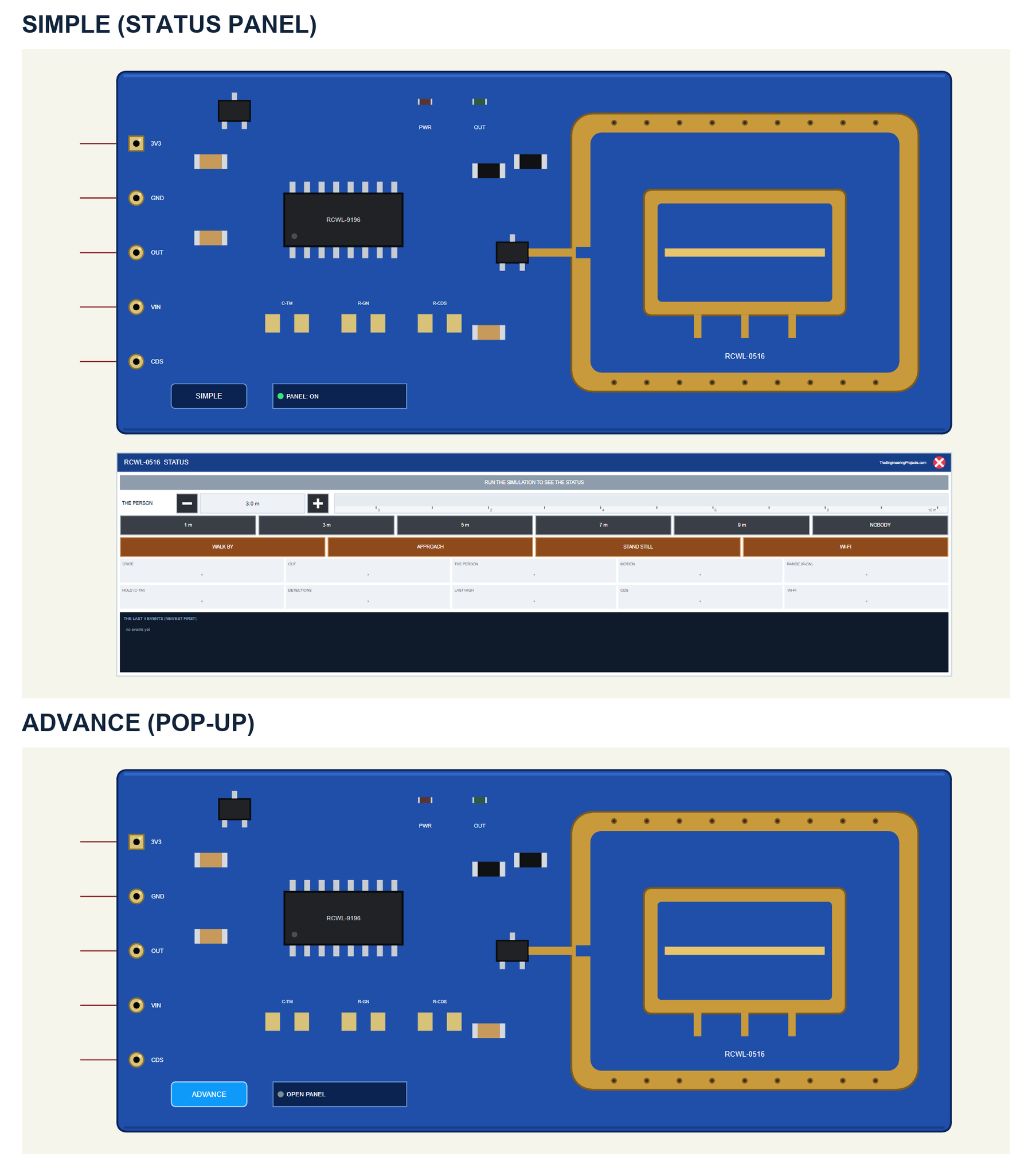
| Simple | Advance | |
|---|---|---|
| Device | RCWL0516TEP | RCWL0516ADVTEP |
| On the schematic | The module and the STATUS panel | The module |
| The person and the actions | On the STATUS panel | In the pop-up |
| Status | Banner, a ruler, 10 readouts, the last 4 events | A pop-up: Sensor, Event log, Tests |
Download RCWL-0516 Microwave Radar Sensor Library for Proteus
Click the button below to download RCWL-0516-Microwave-Radar-Library-for-Proteus-v1.0.zip (about 1.25 MB, without the C++ source code of the model):
RCWL-0516 Microwave Radar Motion Sensor Library for Proteus V1.0- README.txt: the devices, installation, the demo, wiring, the test tools and real hardware.
- Proteus Library Files:
TEPRCWL0516.LIBandArduinoV4TEP.LIBfrom our Arduino Library for Proteus V4.0. - Proteus Model Files:
TEPRCWL0516.DLLandTEPARDUINO.DLL. - Proteus Simulation:
RCWL-0516-Radar-ArduinoUnoV4.pdsprj,RCWL0516_Motion_Demo.hexand copies of the two DLLs. - Arduino Code:
RCWL0516_Motion_Demo.ino- it needs no library.
No Proteus yet? Read How to Download and Install Proteus 7 and 8. New to libraries? Follow How to Install a New Library in Proteus.
How to Install RCWL-0516 Microwave Radar Sensor Library for Proteus
- Close Proteus and extract the whole zip file, for example to your Desktop.
- Copy the two files from Proteus Library Files into the LIBRARY folder of Proteus (usually
C:\Program Files (x86)\Labcenter Electronics\Proteus 8 Professional\LIBRARY). - Copy
TEPRCWL0516.DLLandTEPARDUINO.DLLfrom Proteus Model Files into the MODELS folder. - Delete
TEPRCWL0516.IDXfrom the LIBRARY folder if it is there. - Start Proteus, press P and search for RCWL.
Tip: keep the Proteus Simulation folder together, because the project needs its .hex file and the DLLs beside it. The library is tested in Proteus 8.5; Proteus 7 is not supported.
The RCWL-0516 Parts in Proteus
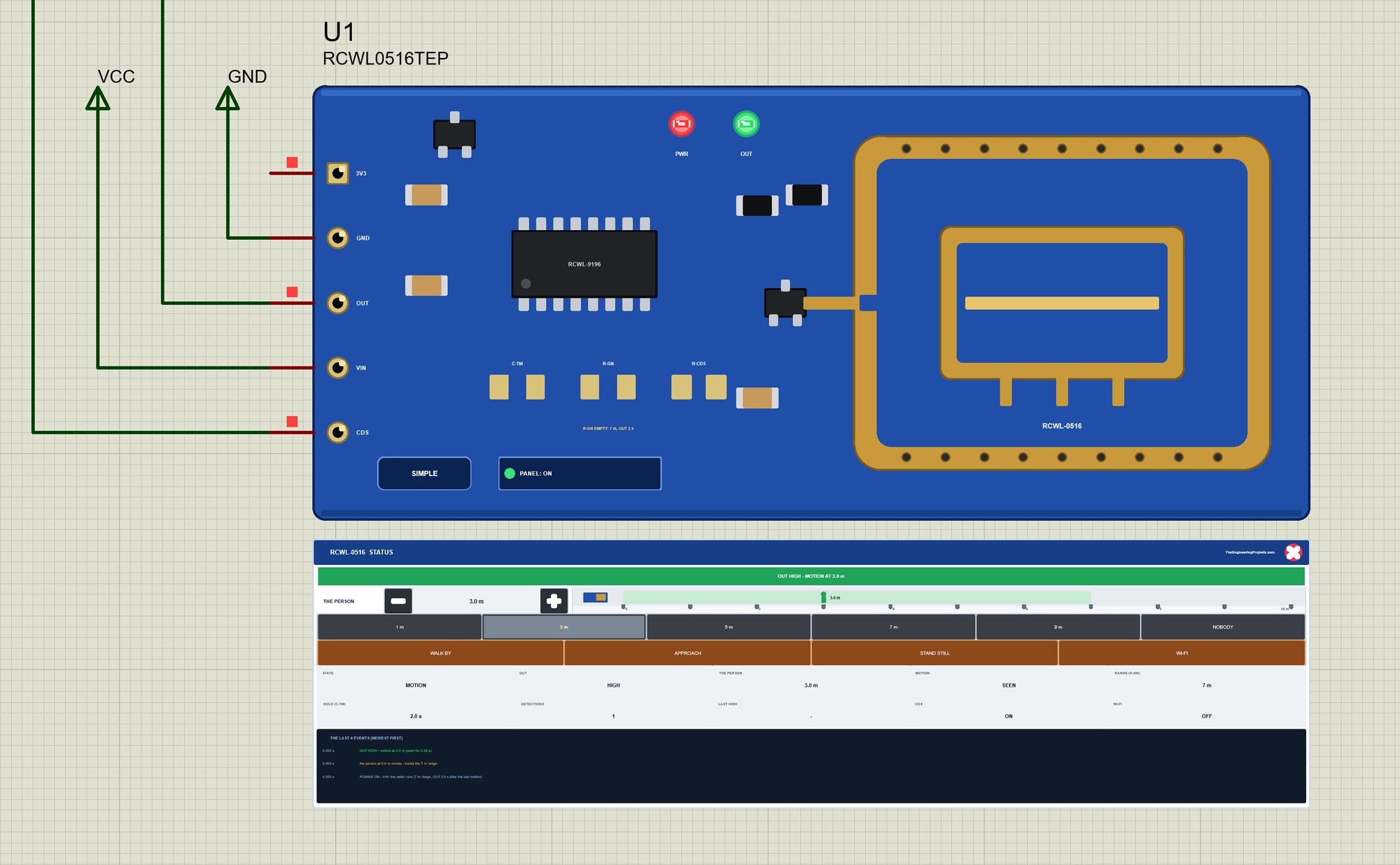
Two LEDs sit on the board: PWR while VIN and GND power the module, and OUT while OUT is HIGH. Under the pads the board writes what they mean: R-GN EMPTY: 7 m, OUT 2 s here. The LEDs, the badge, the button and the panels are TEP additions; the real board has none of them.
The Simple device adds the STATUS panel. Its banner says what OUT does and why: green for motion, amber when the person stands still, is out of range or CDS is LOW, red for a false trigger. Below it are the controls: THE PERSON with - and + (0.5 m a click) and a ruler from 0 to 10 m with the range shaded; six presets - 1, 3, 5, 7, 9 m and NOBODY; and four actions - WALK BY, APPROACH, STAND STILL and WI-FI. Ten readouts follow - the state, OUT, the person, the motion, the range, the hold, the detections, the last HIGH time, CDS and Wi-Fi - and the last four events.
The red X closes the STATUS panel, and the PANEL button on the board opens it again:
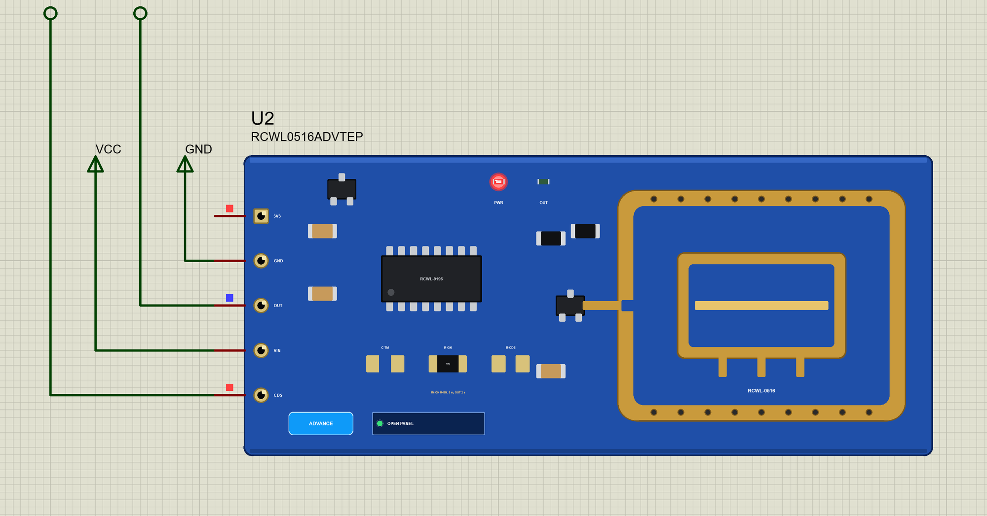
The Advance device keeps the schematic clean: only the module. Its live data opens in a pop-up window at Run, and the OPEN PANEL button on the board brings the window back. The properties set the start: DISTANCE (the person in m, 0 for nobody in front), MOVING (YES or NO), RGN (NONE for 7 m or 1M for 5 m) and HOLD (OUT's time after the last motion, 2 s like an empty C-TM).
The Demo Circuit
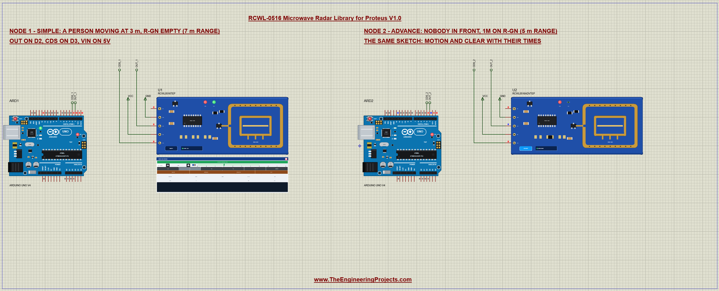
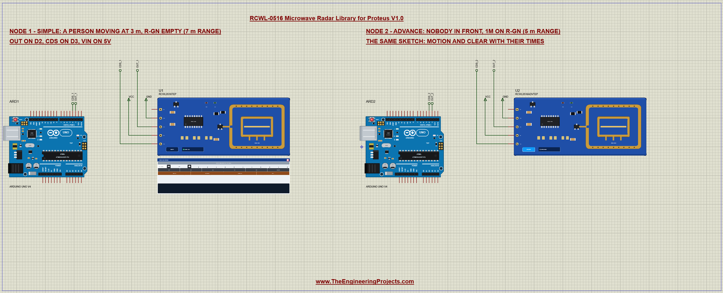
The demo project has two nodes, each an Arduino UNO V4.0 from our Arduino UNO Library for Proteus V4.0 with an RCWL-0516. On both, OUT goes to D2 and CDS to D3; VIN and GND are Proteus power terminals. Node 1 has a person moving at 3 m and R-GN empty, so its range is 7 m. Node 2 has nobody in front and 1M on R-GN, so its range is 5 m. Both UNOs run the same RCWL0516_Motion_Demo.hex.
Wiring
| Module | Arduino UNO |
|---|---|
| VIN | 5V (the board takes 4 to 28 V) |
| GND | GND |
| OUT | D2 (3.3 V when HIGH) |
| CDS | D3 (optional: LOW = detection off) |
| 3V3 | - (a 3.3 V output) |
OUT is a 3.3 V signal, and 3.3 V is a valid HIGH for a 5 V UNO, so no level shifter is needed. D2 is one of the two pins of the UNO with an external interrupt, which the sketch uses. CDS is optional; the demo wires it to D3 so that you can switch the sensor off from the serial monitor. In Proteus, OUT and CDS reach their UNO through net labels, OUT_1 and CDS_1 for node 1 and OUT_2 and CDS_2 for node 2. The serial monitor needs no wires at all, because it is built into the UNO V4.0.
The Arduino Code
The demo sketch needs no library. New to Arduino? Start with Arduino Tutorial for Beginners and Introduction to Arduino UNO. Reading the sensor is as simple as digitalRead(2), but the sketch wants every edge of OUT with its exact time, so it uses an interrupt:
const uint8_t OUT_PIN = 2, CDS_PIN = 3, LED_PIN = LED_BUILTIN;void onOut() { // the interrupt: OUT rose or fell
changed = true;
edgeAt = millis();
}onOut() runs on every change of D2, rising or falling, and only notes the time. setup() attaches it and leaves CDS HIGH with the pin's pull-up:
pinMode(CDS_PIN, INPUT_PULLUP); // CDS HIGH (the pull-up): detection on attachInterrupt(digitalPinToInterrupt(OUT_PIN), onOut, CHANGE);
changed = true; // OUT may be HIGH alreadyThe last line makes the loop look at OUT once at the start, because a person may already be moving when the sketch begins. In loop() the sketch takes the time from the interrupt with interrupts off for a moment, so it cannot change halfway:
  noInterrupts();
  changed = false;
  const unsigned long at = edgeAt;
  interrupts();
const bool out = digitalRead(OUT_PIN) == HIGH;
if (out == lastOut) return;
lastOut = out;Then it prints one line for each edge: MOTION with a count when OUT rises, and clear with how long OUT was HIGH when it falls. The UNO's L LED follows OUT:
  if (out) {                                     // OUT rose: motion
    highAt = at;
    count++;
    Serial.print('#'); Serial.print(count);
    Serial.print(F("  MOTION  at ")); seconds(at); Serial.println();
  } else {                                       // OUT fell: nothing moved for the hold time
    Serial.print(F("    clear   at ")); seconds(at);
    Serial.print(F("  (OUT HIGH for ")); seconds(at - highAt); Serial.println(')');
  }
OFF, ON and STATUS
Three commands come from the serial monitor. OFF makes D3 an output and drives CDS LOW; ON gives the pin back to its pull-up:
void setSensor(bool on) {
  sensorOn = on;
  if (on) pinMode(CDS_PIN, INPUT_PULLUP);
  else { pinMode(CDS_PIN, OUTPUT); digitalWrite(CDS_PIN, LOW); }
  Serial.println(on ? F("ON: CDS HIGH - detection on") : F("OFF: CDS LOW - the sensor ignores motion"));
}
STATUS prints OUT, the number of detections, ON or OFF and the time since the start:
void status() {
  Serial.print(F("STATUS: OUT "));
  Serial.print(digitalRead(OUT_PIN) ? F("HIGH") : F("LOW"));
  Serial.print(F(", ")); Serial.print(count); Serial.print(F(" detections, sensor "));
  Serial.print(sensorOn ? F("ON") : F("OFF"));
  Serial.print(F(", up ")); seconds(millis()); Serial.println();
}
The HEX file is in the package, so you do not need the Arduino IDE to run the demo. To change the sketch, export the compiled binary as in How to get the HEX file from Arduino. It needs 5,924 bytes of flash and 262 bytes of RAM.
The Serial Monitor
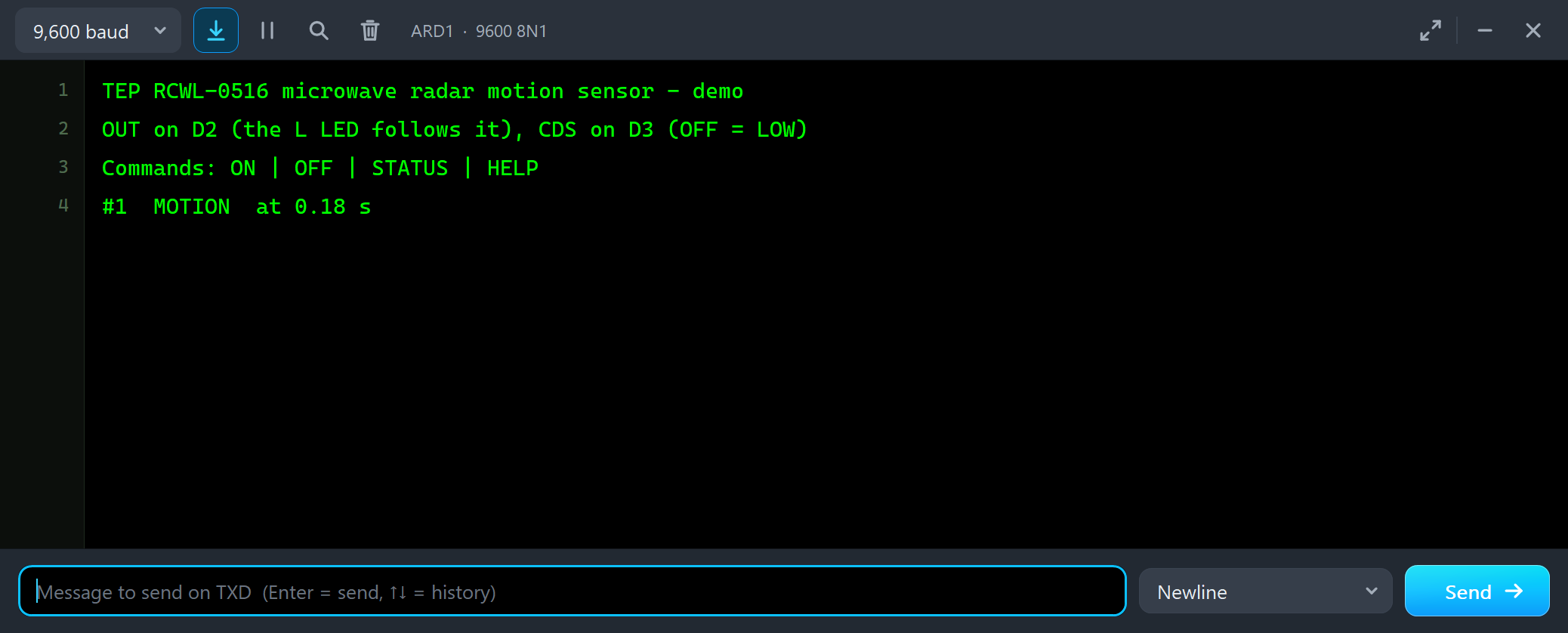
Both UNOs have the serial monitor built in, and it opens at Run. The screenshots use its Simple interface. Node 1 starts like this:
TEP RCWL-0516 microwave radar motion sensor - demo
OUT on D2 (the L LED follows it), CDS on D3 (OFF = LOW)
Commands: ON | OFF | STATUS | HELP
#1  MOTION  at 0.18 s
Its person moves from the start, so OUT goes HIGH after a quarter of a second and the sketch prints #1 MOTION. The time is the sketch's own millis(), which starts a little after the simulation: the simulation log puts the same edge at 0.2500 s. Node 2 has nobody in front, so its monitor shows only the first three lines for now.
The Advance Pop-Up Window
At Run, the Advance module opens its own window, RCWL-0516 Microwave Radar, with the look of our TEP Serial Monitor Advance for Proteus. It has three tabs, Sensor, Event log and Tests, plus Settings and Help behind the gear and question mark icons. The status bar at the bottom always shows the person, OUT and the range.
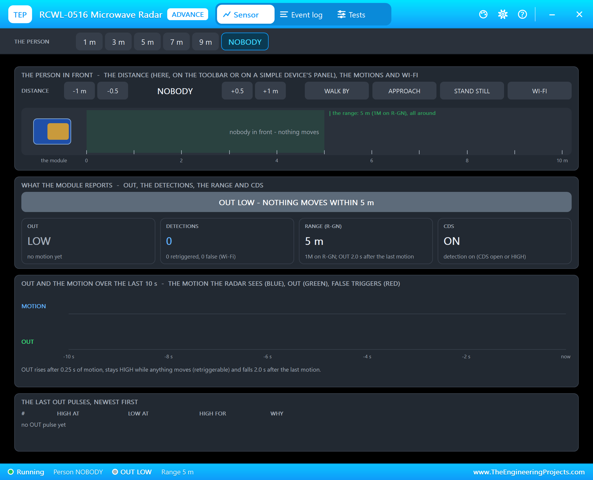
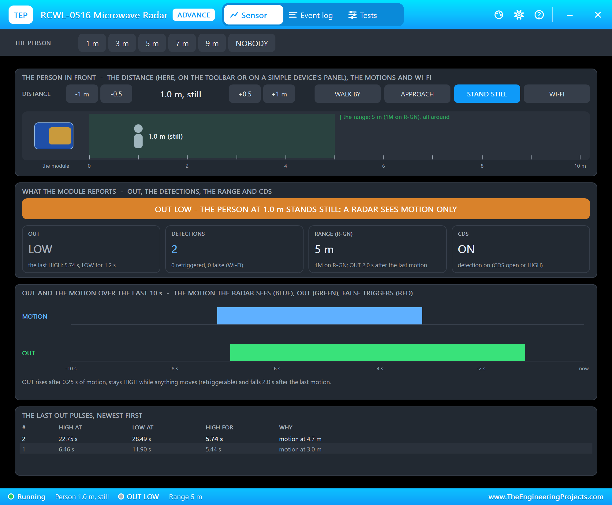
The toolbar carries the presets. The person in front has -1 m, -0.5, +0.5 and +1 m, the four actions and a side view: the module, the range shaded green and the person on a ruler from 0 to 10 m. What the module reports shows the banner, OUT, the detections, the range and CDS. OUT and the motion over the last 10 s draws a time line: the motion the radar sees in blue, OUT in green and false triggers in red. At the bottom are the last OUT pulses with their times and why each one happened. We clicked 3 m:
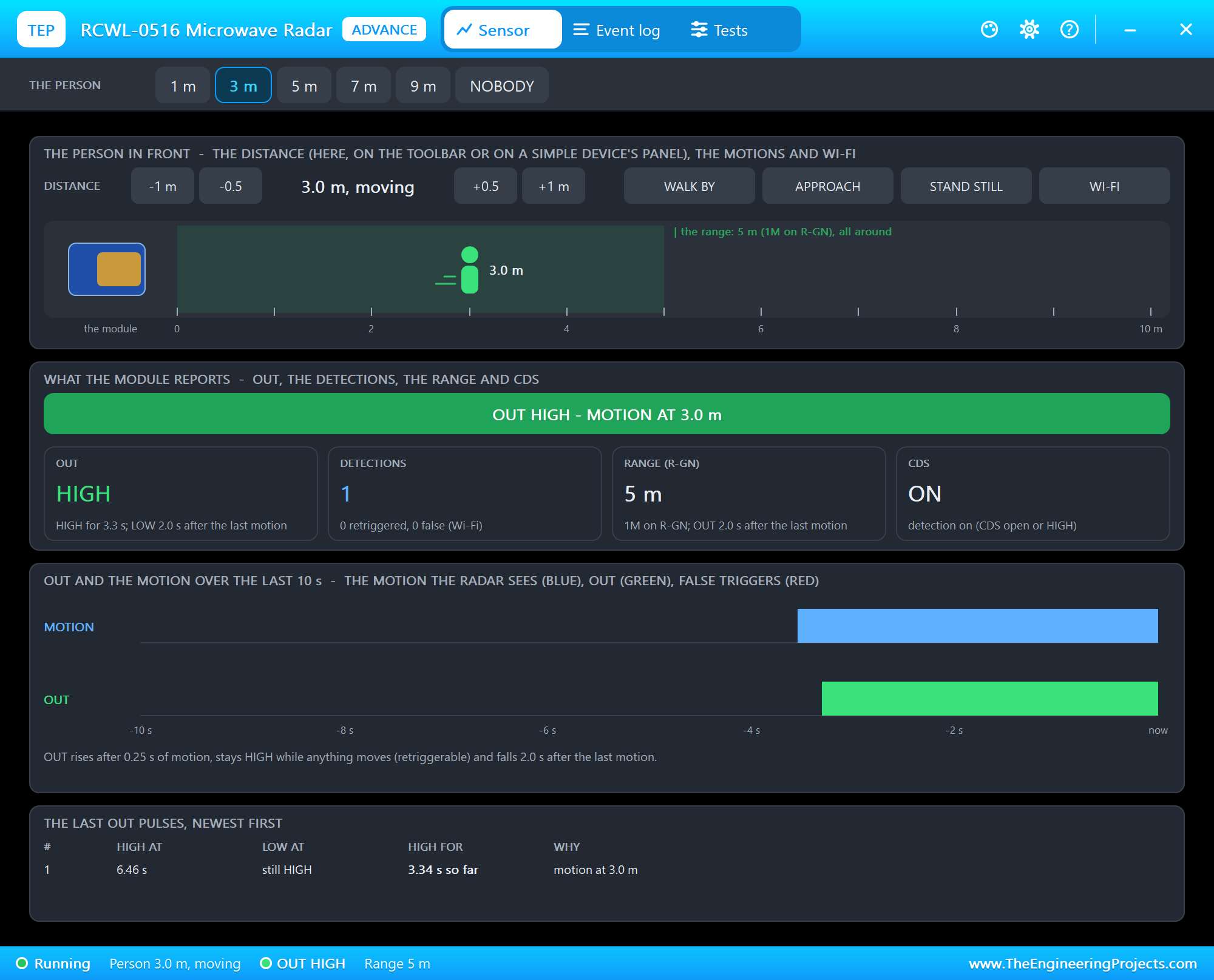
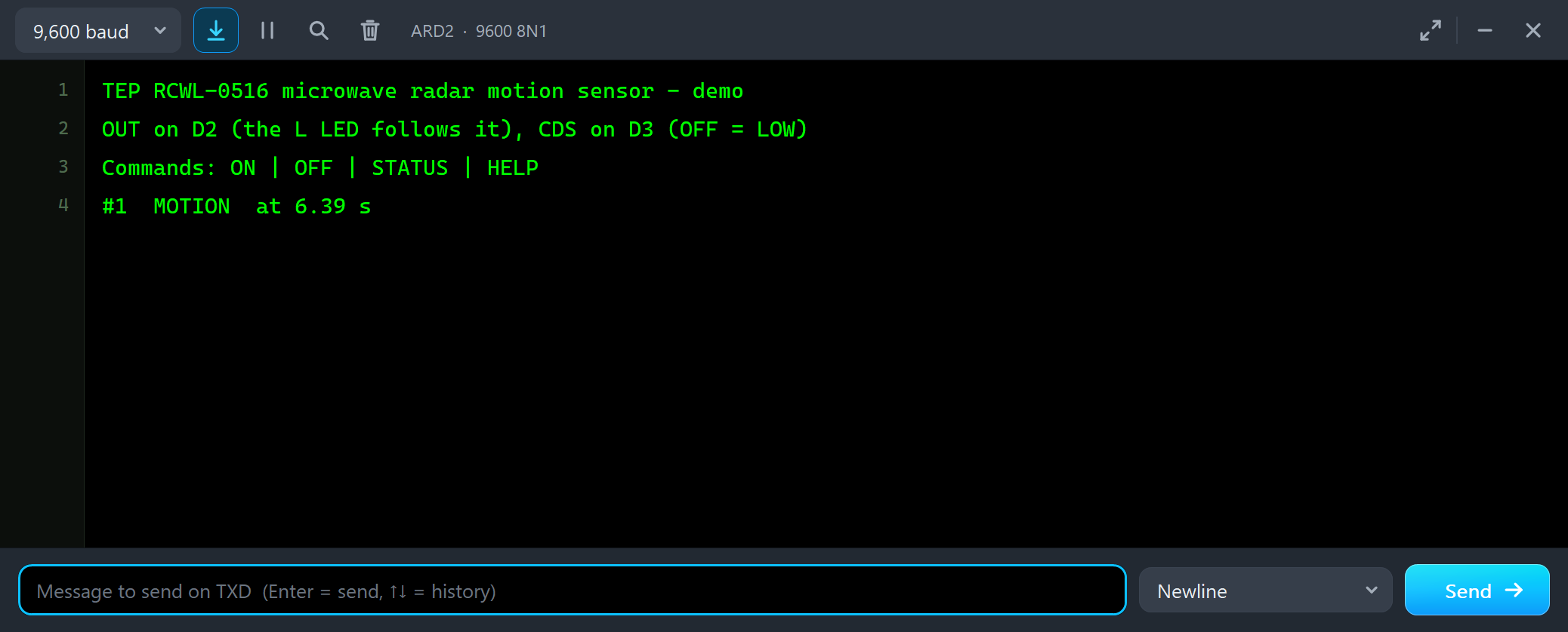
Commands: ON | OFF | STATUS | HELP
#1  MOTION  at 6.39 s
STAND STILL: a Radar Sees Motion Only
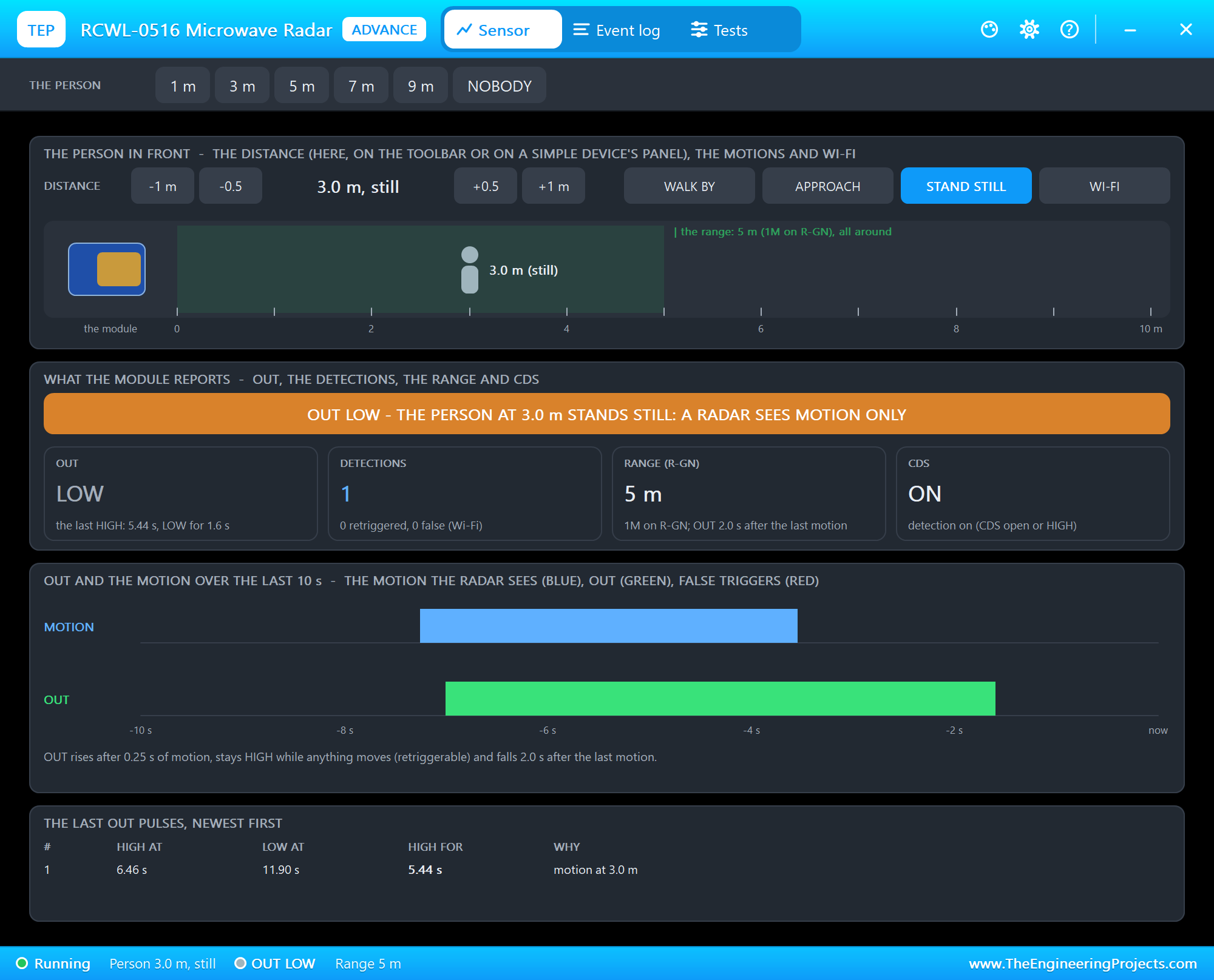
Then we clicked STAND STILL. The person is still there, 3 m from the module, but no longer moves:
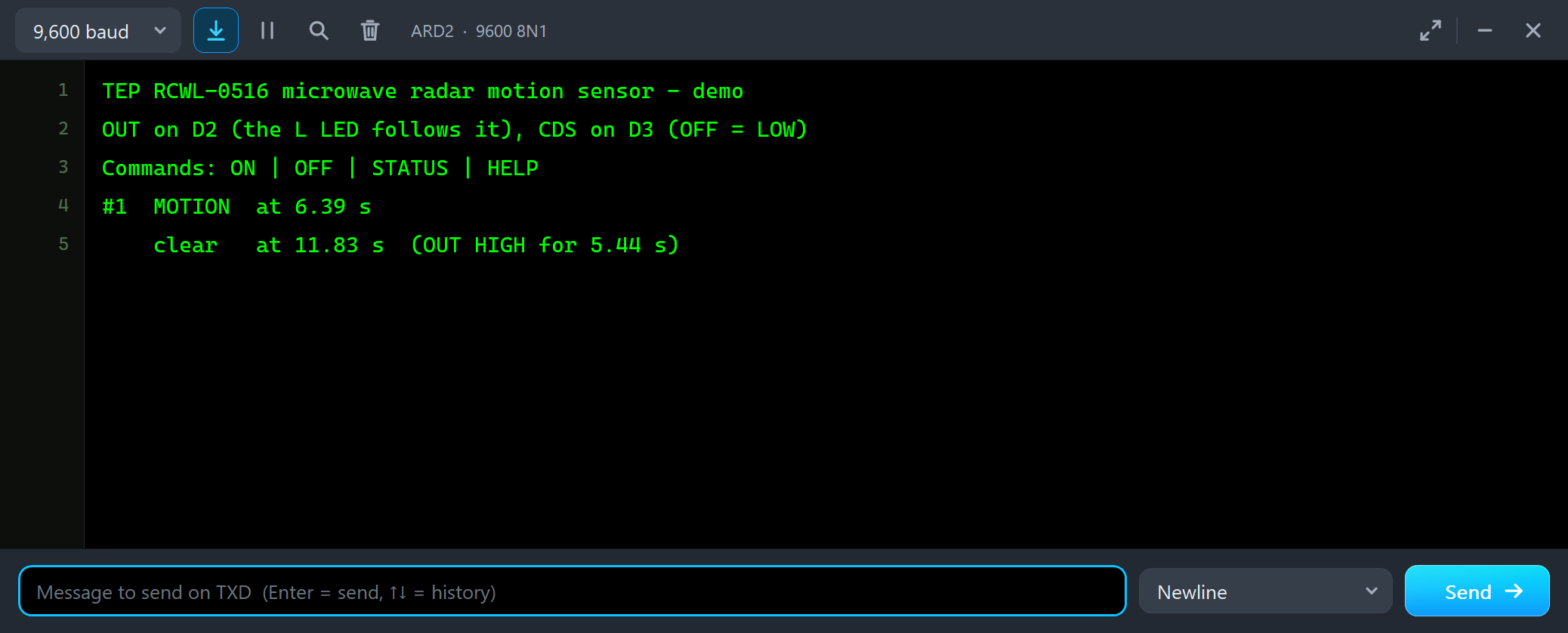
#1  MOTION  at 6.39 s
    clear   at 11.83 s  (OUT HIGH for 5.44 s)
OUT was HIGH for 5.44 s and fell exactly 2 s after the last movement. This is the most important thing to know about the RCWL-0516: it is a motion sensor, not a presence sensor. A person reading at a desk, or asleep, disappears for it. A light that should stay on while someone is in the room needs a longer hold, or a sketch that keeps it on for minutes after the last motion.
7 m: Beyond the Range
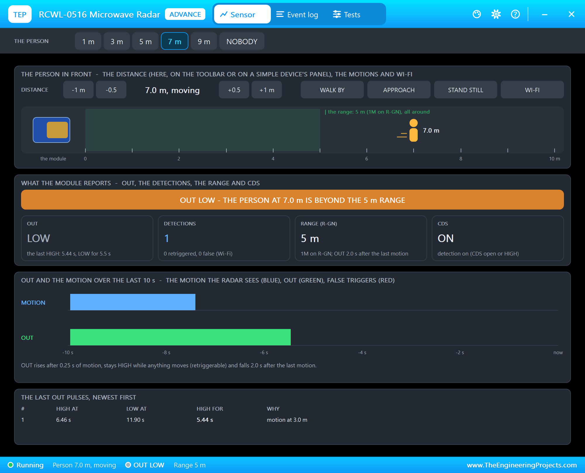
With 1M on R-GN, U2 sees about 5 m. We clicked 7 m: the person moves, the banner turns amber - beyond the 5 m range - and OUT stays LOW, so the monitor prints nothing. On node 1, with R-GN empty, the same person would be seen. That is what R-GN is for: a sensor in a hall that should not wake up for people in the next room.
APPROACH
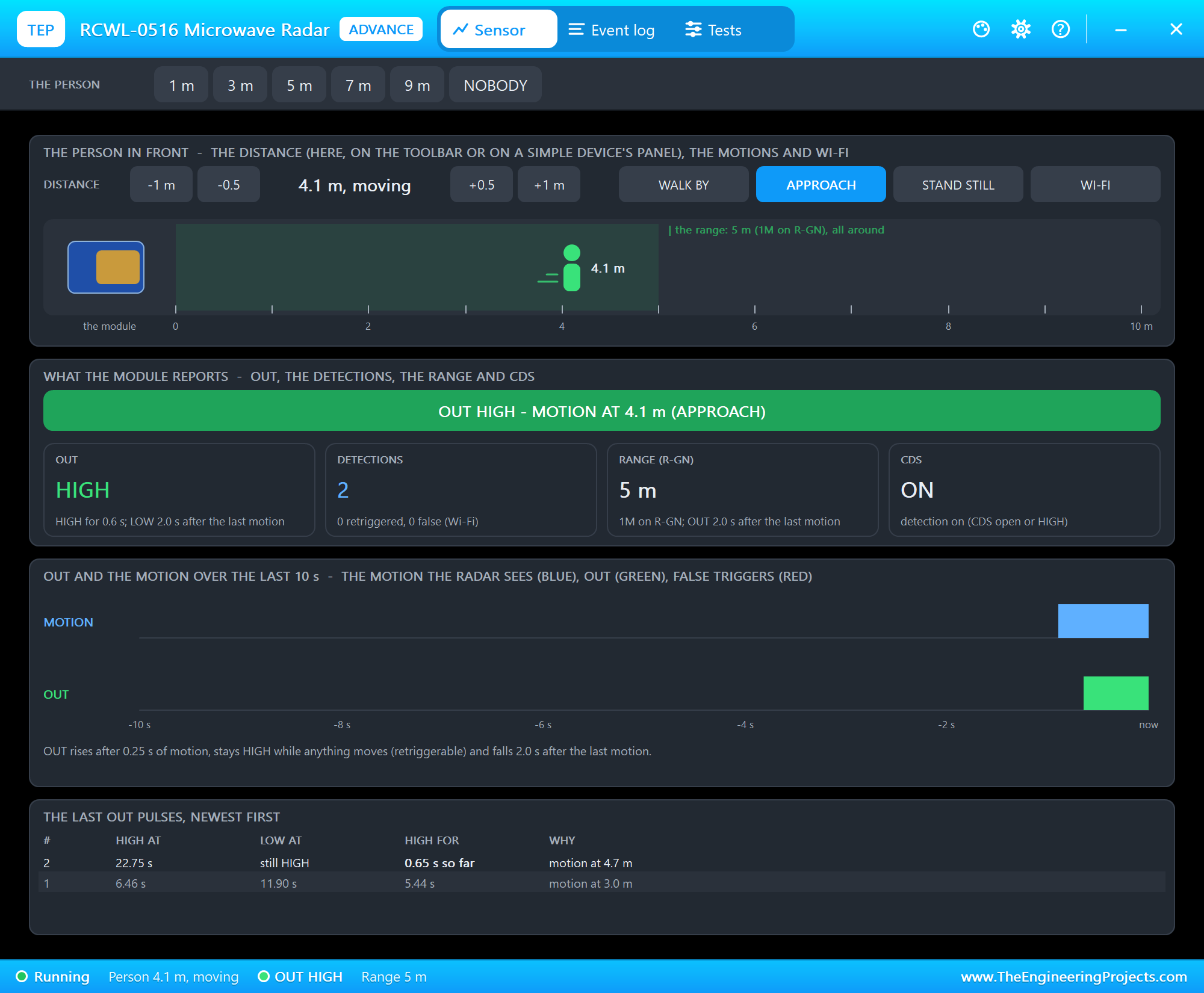
APPROACH lets a person walk from 10 m straight to the module at 1 m/s and stop at 1 m:
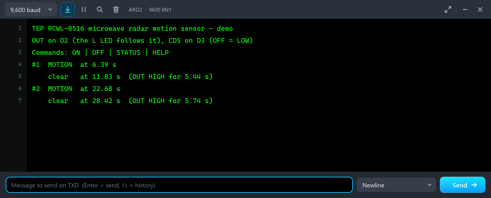
#2  MOTION  at 22.68 s
    clear   at 28.42 s  (OUT HIGH for 5.74 s)
For the first five seconds the person is too far, and nothing happens. At 5 m they enter the range, and a quarter of a second later OUT rises: the log says motion at 4.7 m. OUT stays HIGH all the way in - one pulse, not one per step - and falls 2 s after the person stops at 1 m. So the end of the pulse tells you when the motion ended, not when the person left.
WI-FI: False Triggers
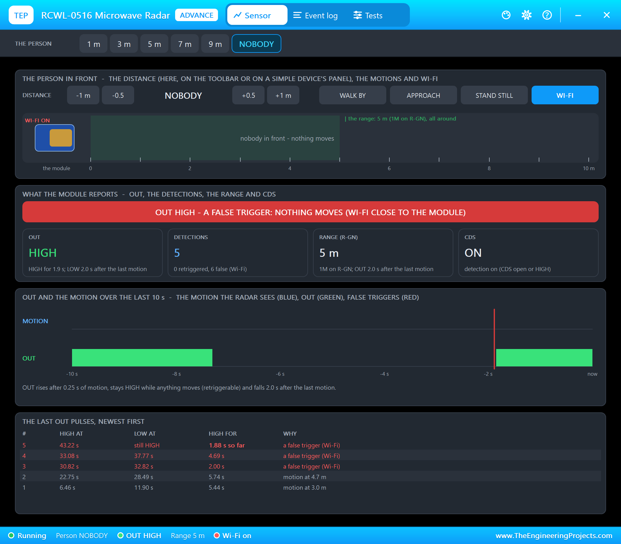
Many users see the RCWL-0516 trigger with nobody around when a Wi-Fi module - an ESP8266 or an ESP32 - sits right next to it. We clicked NOBODY, then WI-FI:
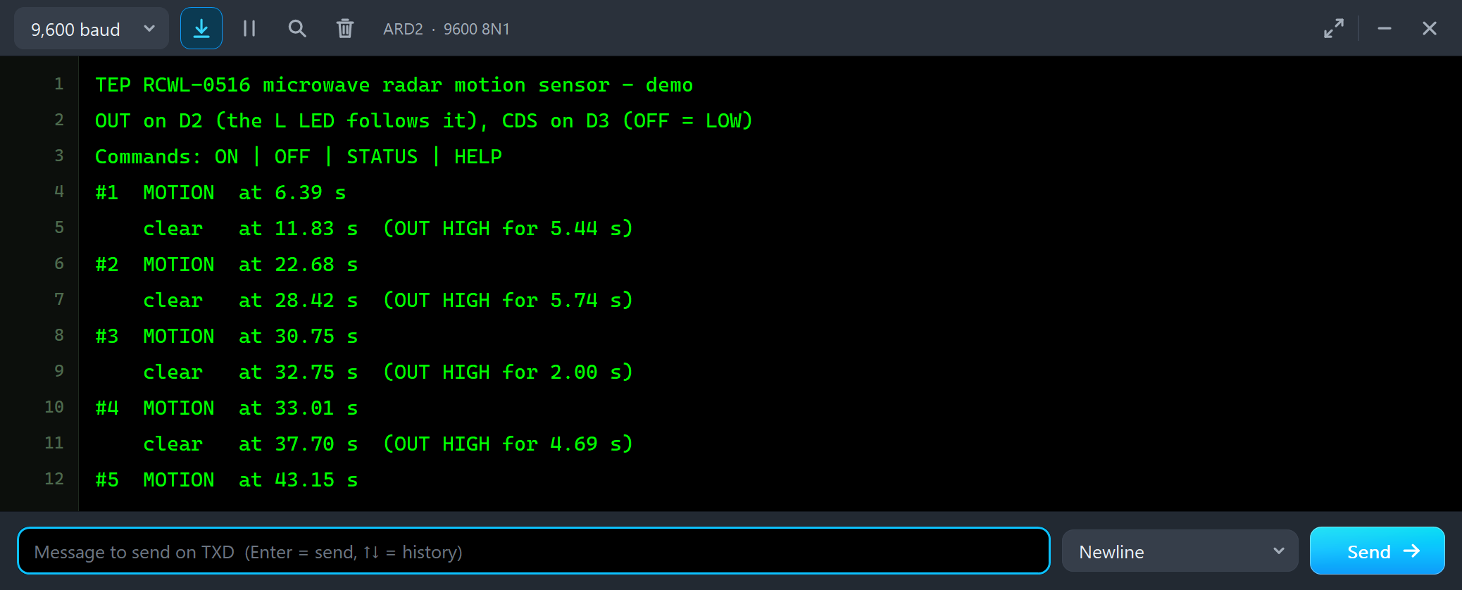
#3  MOTION  at 30.75 s
    clear   at 32.75 s  (OUT HIGH for 2.00 s)
#4  MOTION  at 33.01 s
    clear   at 37.70 s  (OUT HIGH for 4.69 s)
#5  MOTION  at 43.15 s
Nobody is there, yet the sketch counts three new detections in about 13 seconds, HIGH for 2.00 to 4.69 s. The time line marks each false trigger in red, and the last pulses say a false trigger (Wi-Fi). To the sketch they look exactly like motion, which is why the fix is on the hardware side: keep the Wi-Fi antenna away from the radar and give the board a clean supply. Our ESP8266 based WiFi Modules for IoT Projects shows the modules that cause it.
Move the Person on the STATUS Panel
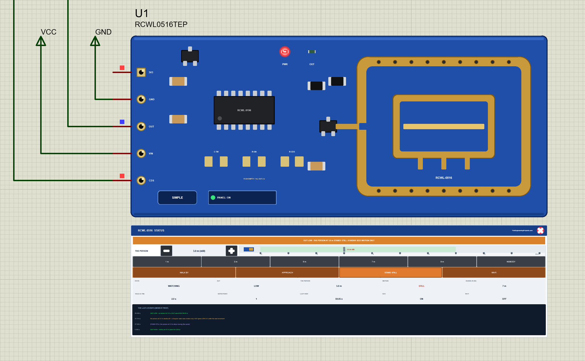
Now let's go back to node 1, with the range of 7 m. We clicked the buttons of U1's STATUS panel with the mouse while the simulation ran. First STAND STILL:
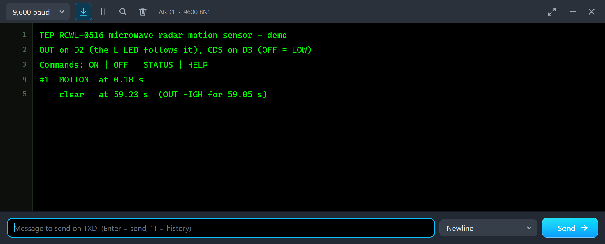
#1  MOTION  at 0.18 s
    clear   at 59.23 s  (OUT HIGH for 59.05 s)
The person had moved since the start, so OUT stayed HIGH for 59.05 s without a break, and the sketch counted one detection, not hundreds. A retriggerable output is great for a light; for a people counter it means one long pulse while a group walks through.
9 m and 5 m
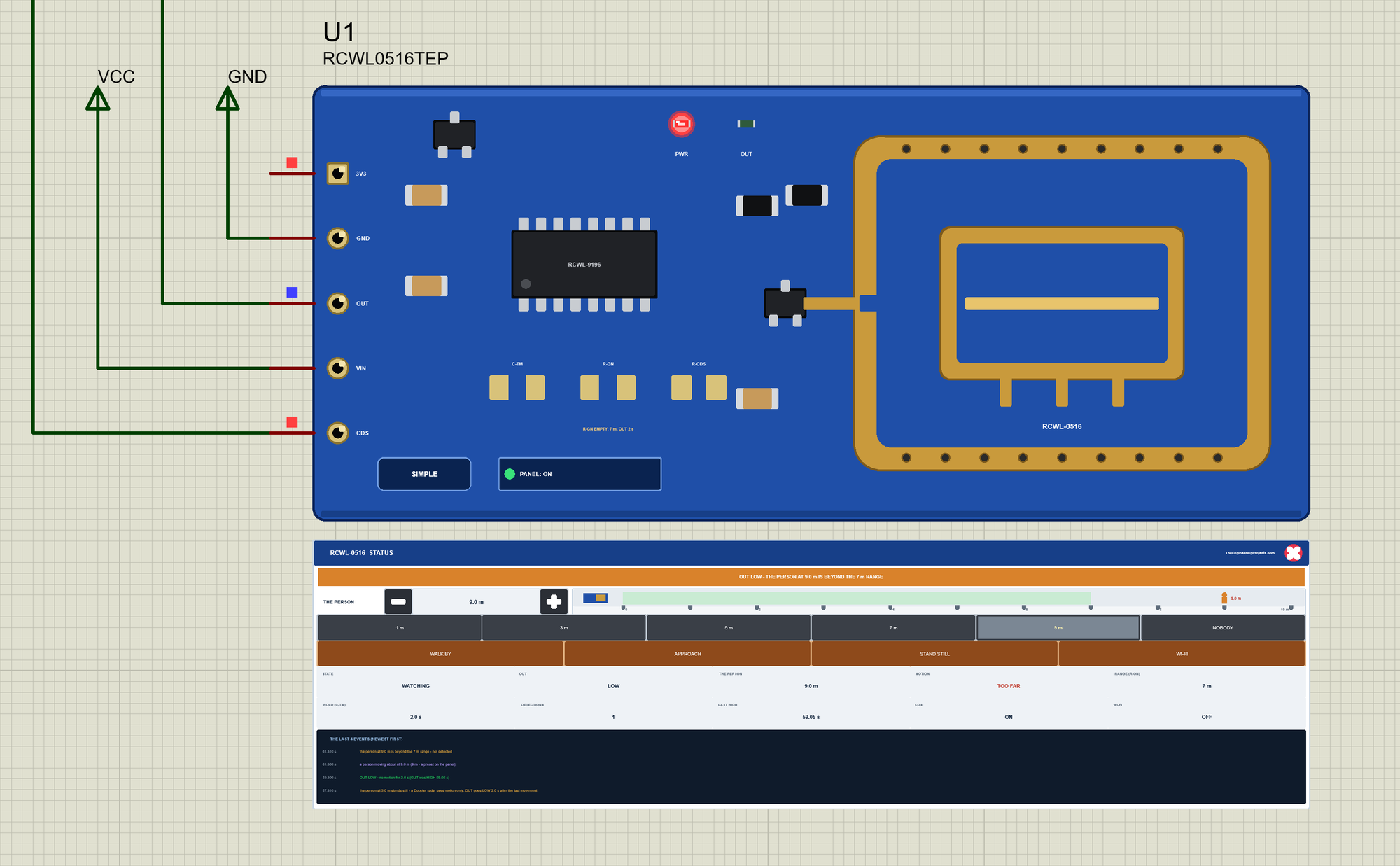
At 9 m the person moves, but beyond the 7 m range, so OUT stays LOW and the monitor stays quiet. Then 5 m:
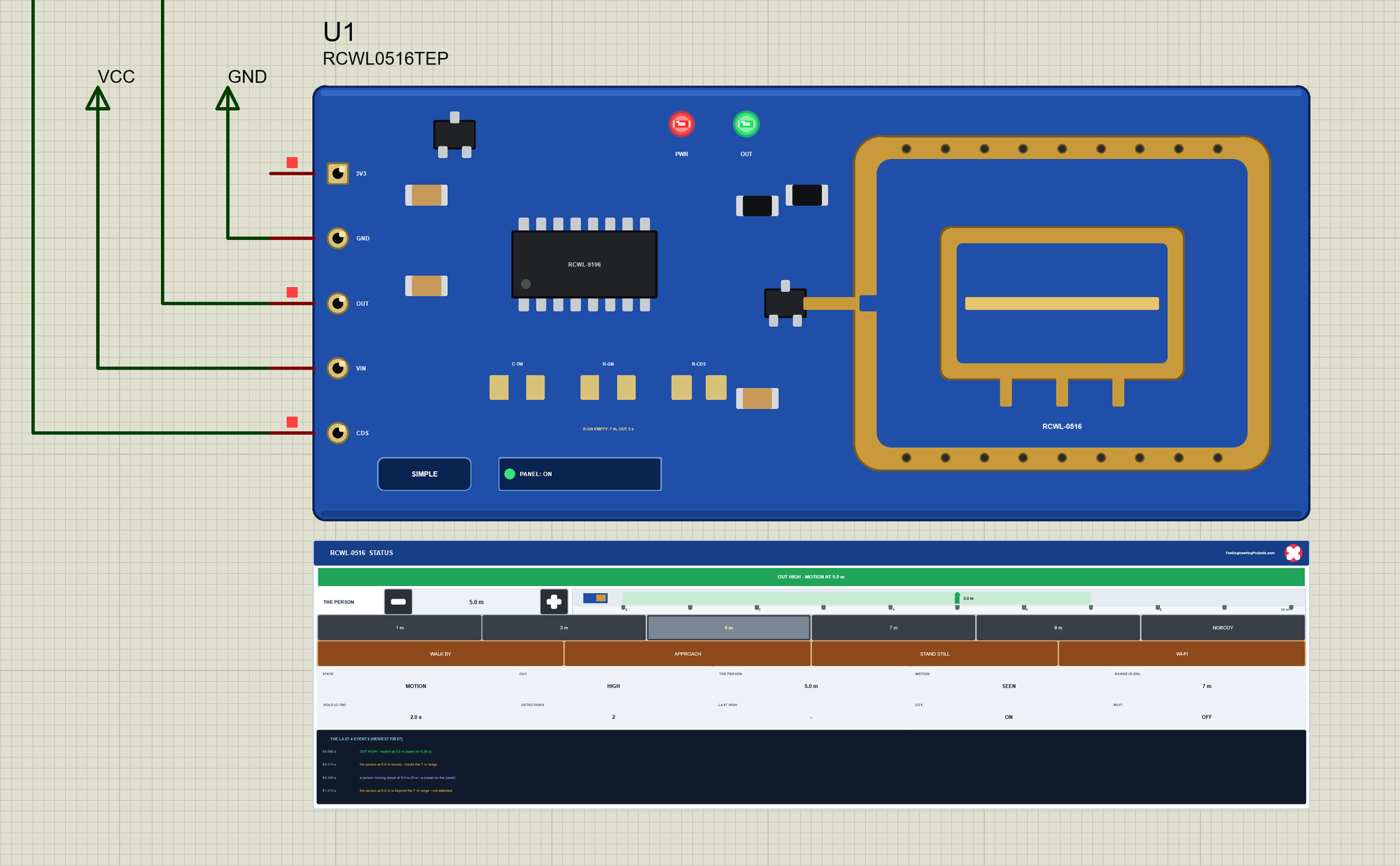
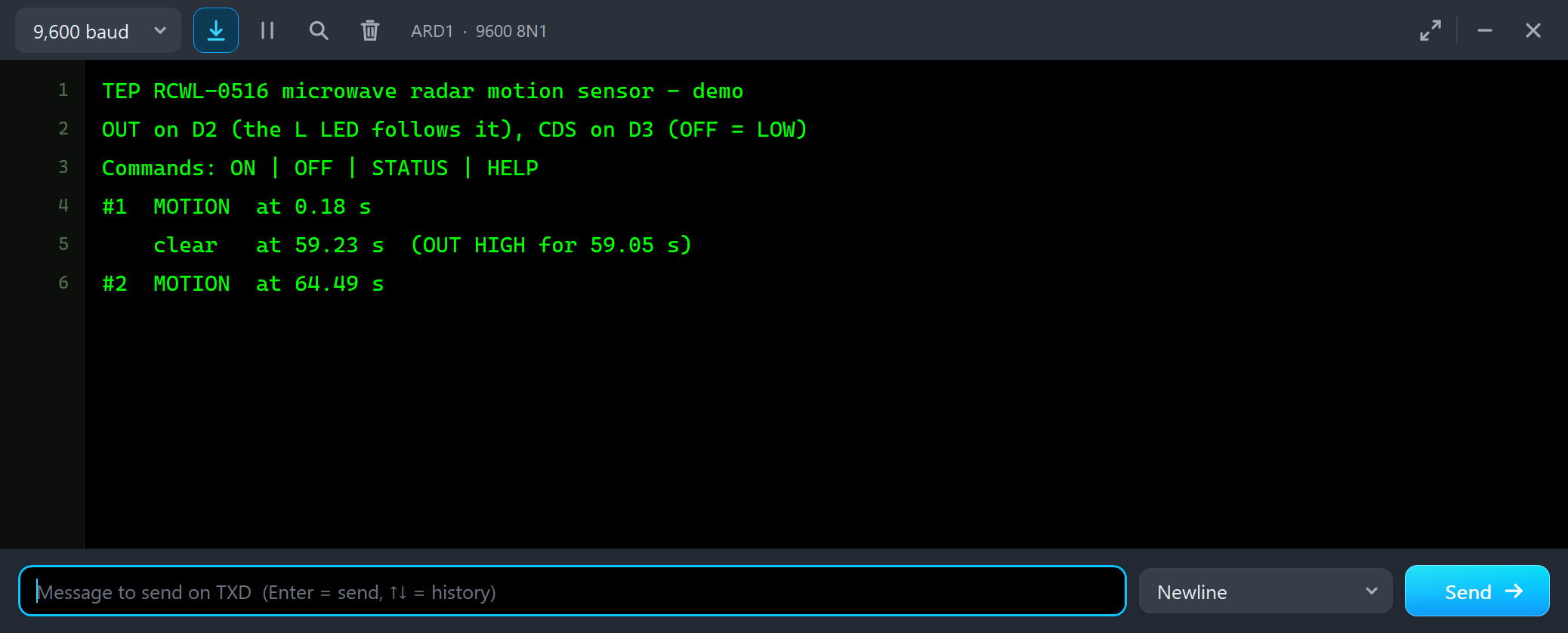
#1  MOTION  at 0.18 s
    clear   at 59.23 s  (OUT HIGH for 59.05 s)
#2  MOTION  at 64.49 s
OFF and ON: the CDS Pin
Then we typed OFF in ARD1's monitor. The sketch drives CDS LOW, while the person keeps moving at 5 m:
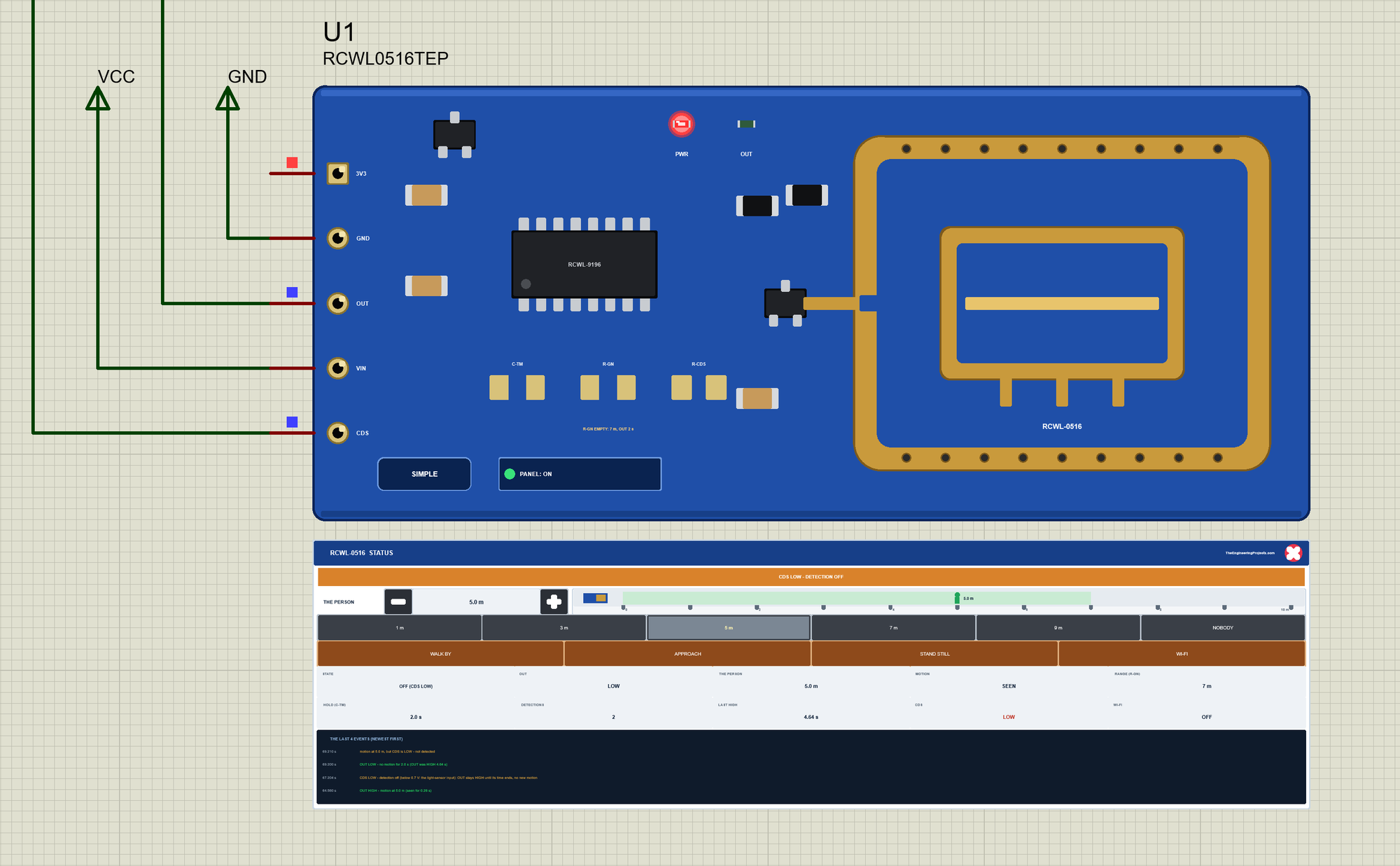
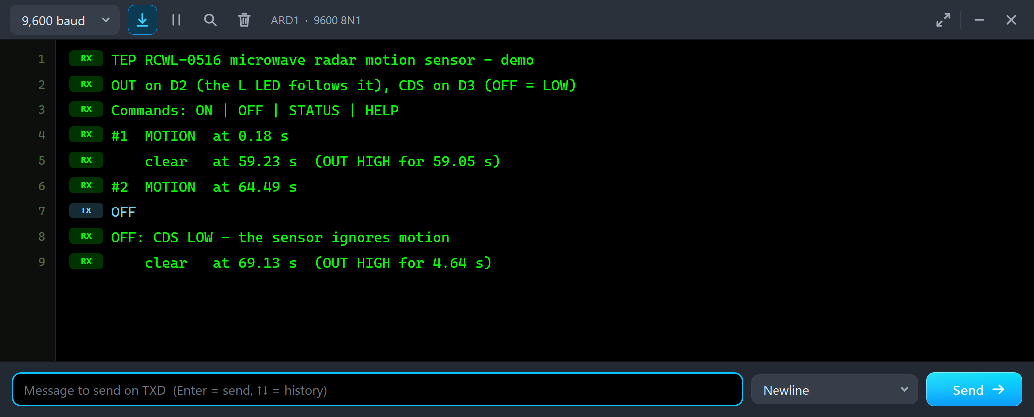
#2  MOTION  at 64.49 s
OFF
OFF: CDS LOW - the sensor ignores motion
    clear   at 69.13 s  (OUT HIGH for 4.64 s)
With CDS LOW the module stops seeing motion, but OUT does not drop at once: it finishes its time and falls 2 s later, although the person is still moving. On a real board, CDS is meant for a light sensor: an LDR from CDS to GND pulls it LOW in daylight, so the lamp works only at night - the same idea as our Automatic Light Detector using LDR in Proteus. Then ON:
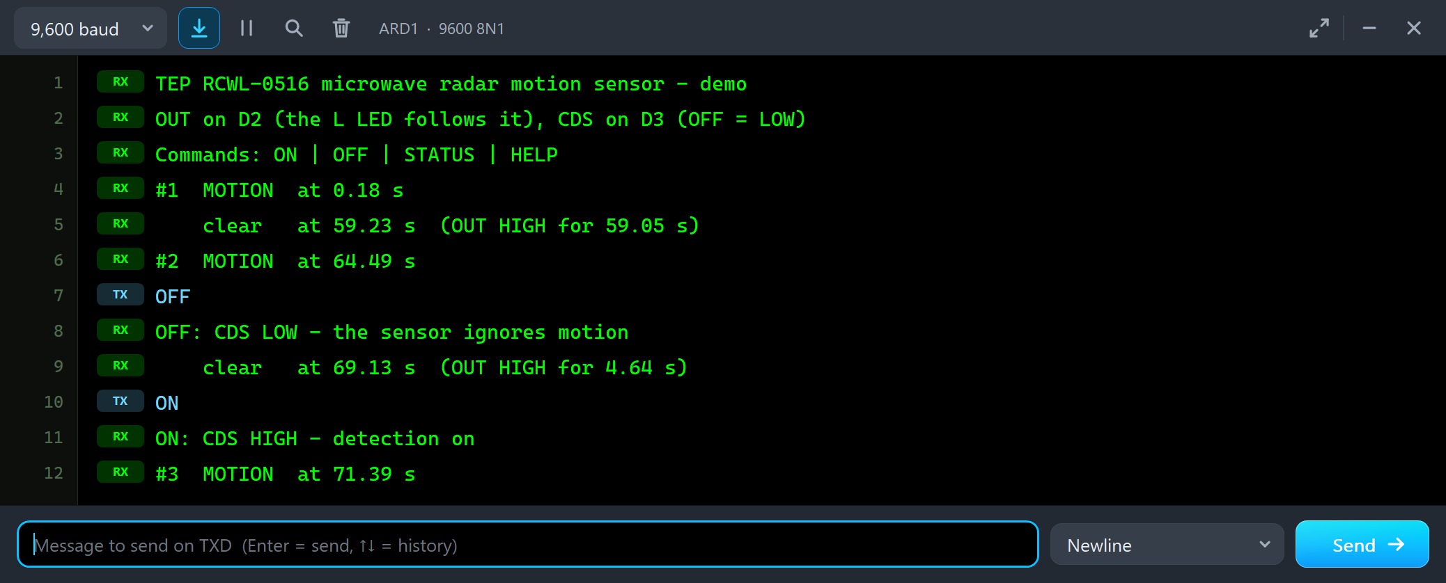
    clear   at 69.13 s  (OUT HIGH for 4.64 s)
ON
ON: CDS HIGH - detection on
#3  MOTION  at 71.39 s
The person never stopped moving, so the radar sees them again as soon as CDS goes HIGH: #3 MOTION.
NOBODY and WALK BY
We clicked NOBODY - OUT falls 2 s later - and then WALK BY: a person walks across in front of the module at 1.2 m/s, from 4 m on one side to 4 m on the other, and goes:
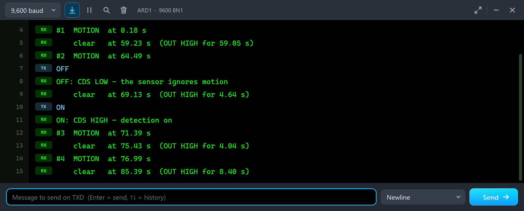
#3  MOTION  at 71.39 s
    clear   at 75.43 s  (OUT HIGH for 4.04 s)
#4  MOTION  at 76.99 s
    clear   at 85.39 s  (OUT HIGH for 8.40 s)
The walk takes about 6.7 s, and the whole way is inside the 7 m range, so OUT is HIGH for 8.40 s: the walk plus the 2 s hold. Last, STATUS:
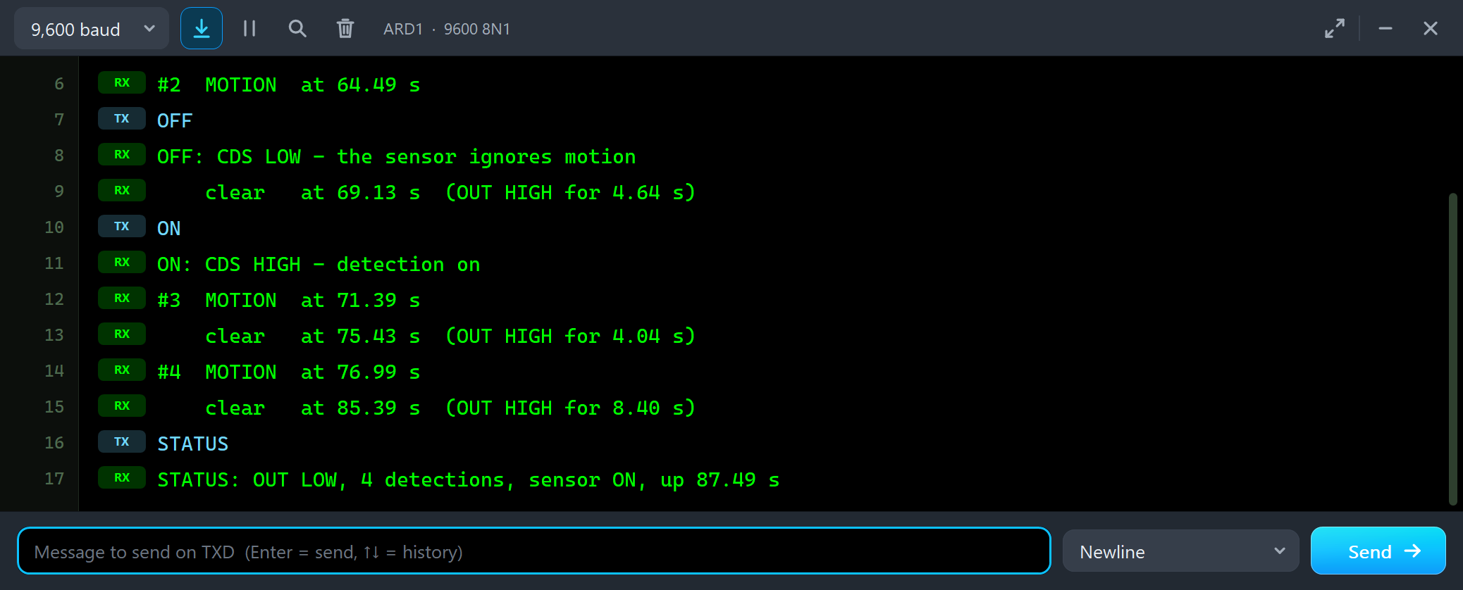
    clear   at 85.39 s  (OUT HIGH for 8.40 s)
STATUS
STATUS: OUT LOW, 4 detections, sensor ON, up 87.49 s
The Test Tools
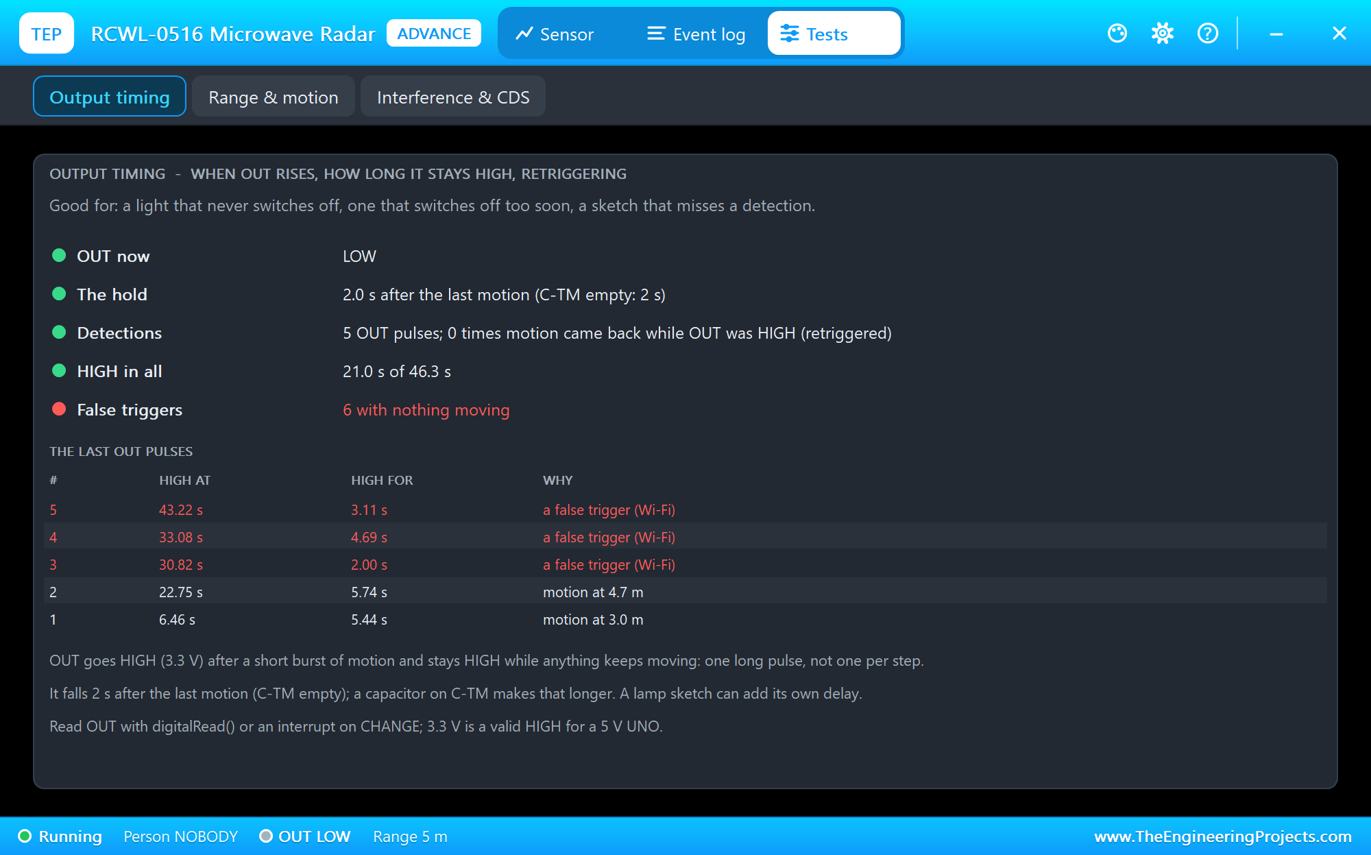
The Output timing tool is the one to open when a light never switches off, switches off too soon, or a sketch misses a detection. It shows OUT now, the hold (C-TM), the detections and how often motion came back while OUT was still HIGH, the time HIGH in all, and the false triggers - here 5 OUT pulses and 6 false triggers - with the last pulses, their length and why.
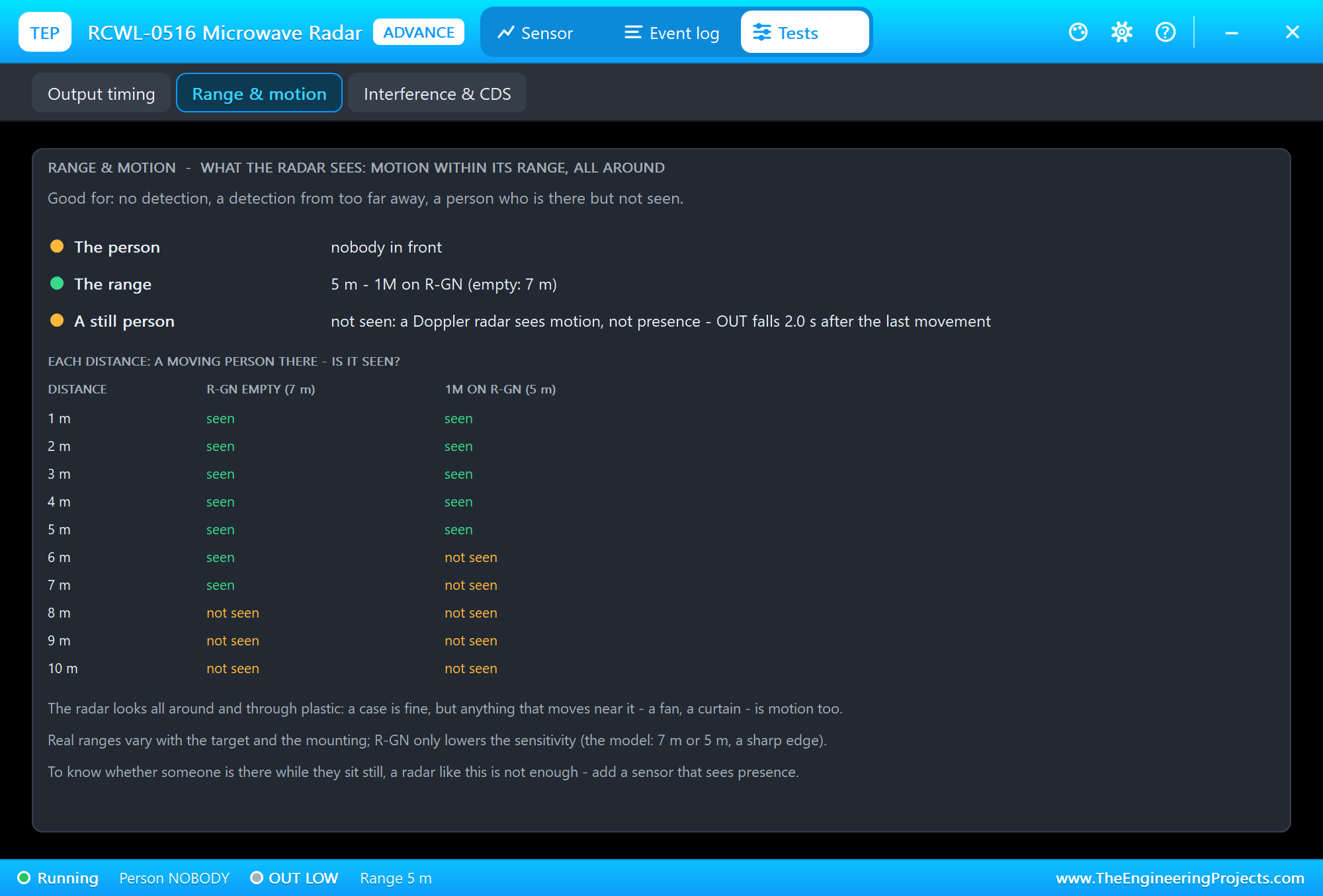
The Range & motion tool answers "why is nothing detected?" and "why is it detected from so far away?". It shows the person and the range, explains why a still person is not seen, and lists for 1 to 10 m whether a moving person is seen with R-GN empty (up to 7 m) and with 1M (up to 5 m).
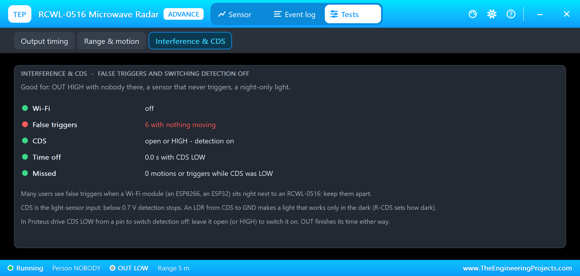
The Interference & CDS tool is for OUT HIGH with nobody there, a sensor that never triggers, or a night-only light. It shows Wi-Fi, the false triggers, CDS, the time CDS was LOW, and the motions missed meanwhile.
The Event Log
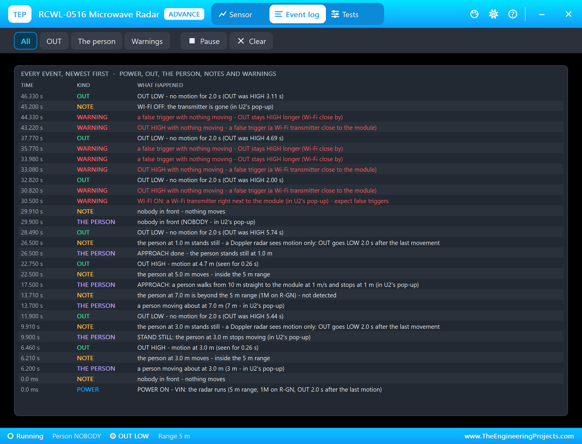
The Event log lists everything that happened, newest first: power, OUT, the person and the actions, notes and warnings. Filter it by OUT, the person or warnings, pause it, or clear it. Each note says why: at 9.910 s, "the person at 3.0 m stands still - a Doppler radar sees motion only".
The Simulation Log
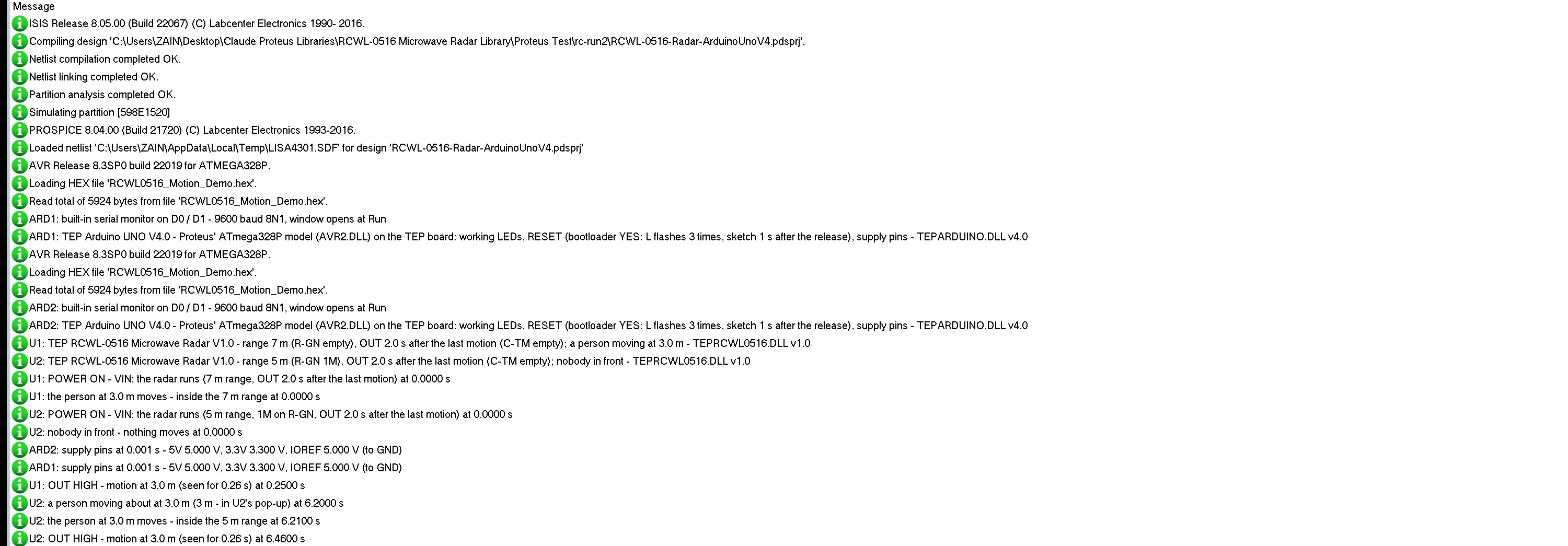
The modules also write to the simulation log of Proteus, with the exact simulation time. This part shows the start and node 2's STAND STILL:
U1: TEP RCWL-0516 Microwave Radar V1.0 - range 7 m (R-GN empty), OUT 2.0 s after the last motion (C-TM empty); a person moving at 3.0 m - TEPRCWL0516.DLL v1.0
U2: TEP RCWL-0516 Microwave Radar V1.0 - range 5 m (R-GN 1M), OUT 2.0 s after the last motion (C-TM empty); nobody in front - TEPRCWL0516.DLL v1.0
U1: OUT HIGH - motion at 3.0 m (seen for 0.26 s) at 0.2500 s
U2: STAND STILL: the person at 3.0 m stops moving (in U2's pop-up) at 9.9000 s
U2: the person at 3.0 m stands still - a Doppler radar sees motion only: OUT goes LOW 2.0 s after the last movement at 9.9100 s
U2: OUT LOW - no motion for 2.0 s (OUT was HIGH 5.44 s) at 11.9000 s
Each module first writes its settings: U1 with a range of 7 m and a person moving at 3 m, U2 with 5 m and nobody in front. The last three lines are the STAND STILL we clicked: the person stopped moving at 9.9000 s, and OUT fell at 11.9000 s, 2 s later, after a pulse of 5.44 s - the same 5.44 s that ARD2 printed.
How the Model Works
The module is a digital model. VIN and GND power it; CDS is a digital input; OUT and 3V3 are digital outputs. Inside, the model steps through time on a 10 ms grid: at each step it works out where the person is and whether they move, and whether that motion is inside the range. 0.25 s of motion sets OUT HIGH, more motion keeps it HIGH, and 2 s without motion (HOLD) sets it LOW. CDS LOW stops the model from seeing new motion, and WI-FI adds random false triggers. The model works out when OUT will change next and asks Proteus to call it only then, so it costs very little time.
Troubleshooting
- OUT never goes HIGH: no power on VIN and GND (the PWR LED is off), CDS is LOW (type ON), nobody moves, or the person is beyond the range - 5 m with 1M on R-GN.
- OUT stays HIGH: something keeps moving in range; OUT falls 2 s after the last motion. With WI-FI on: false triggers.
- OUT goes LOW although the person is there: the person stands still - a radar like this sees motion, not presence.
- OUT HIGH with nobody there: a false trigger; the Interference & CDS tool counts them.
- No part or no monitor: TEPRCWL0516.DLL or TEPARDUINO.DLL is missing from MODELS and the project folder; a closed monitor opens again with a click on the UNO's USB port.
Things to Know Before Using a Real RCWL-0516
- Give it room: keep about 1 cm of free space in front of and behind the antenna side, with no metal close by. The radar looks through plastic cases. Our Introduction to Microwave PCB explains why the copper of such boards matters.
- Keep Wi-Fi away and feed the board from a clean supply: both are reported to cause false triggers.
- Anything that moves is motion: fans, curtains, plants in the wind - and people on the other side of a thin wall.
- Edges, not levels: count rising edges for detections, and keep a light on for some time after the last one.
- CDS for night lights: an LDR from CDS to GND switches detection off in the light; a resistor on R-CDS sets how dark.
Limitations of the Simulation
- Not modelled: the microwave itself (3.2 GHz, the antenna, the Doppler signal), the target's size and speed and the real fall-off of the sensitivity with distance (the model has a sharp edge at the range), walls, metal and the module's own supply noise, the voltage on VIN and the current, the 3.3 V regulator, an LDR on CDS (drive CDS LOW instead), the exact time C-TM gives for a capacitor (set HOLD) and the start-up time. The 0.25 s before OUT rises and the Wi-Fi false-trigger rate are the model's values.
- The LEDs, the badge, the panel button and the panels are TEP additions.
- The model is our own, written from the module's published descriptions. This library is not made or endorsed by the makers of the RCWL-0516 or by Labcenter.
- Licences: the demo sketch needs no library. The HEX file contains the Arduino AVR core 1.8.6 with LGPL-licensed code; the licence note and the source link are in the README.
- Tested in Proteus 8.5 in October 2026 (the demo as shipped on two Arduino UNO V4.0 boards with their built-in monitors: 3 m, STAND STILL, 7 m, APPROACH, NOBODY with WI-FI and the three tools on node 2; STAND STILL, 9 m, 5 m, OFF and ON, NOBODY, WALK BY and STATUS on node 1 with the mouse, the red X and PANEL; 103.2 s of simulation took 181 s, about 0.57 x real time with the pop-up and both monitors open). Proteus 7 is not supported.
So, that was all about the RCWL-0516 Microwave Radar Motion Sensor Library for Proteus V1.0. I hope the timing of OUT, the range and the blind spot for people who stand still are clear now, and that your motion light or alarm works from the first run. If you use the RCWL-0516 Microwave Radar Sensor Library for Proteus in a project, please share it in the comments or in our forum, and if you have any questions, ask in the comments and I will help you out. Till the next tutorial, take care and have fun!
Comments
0